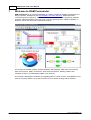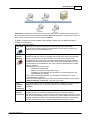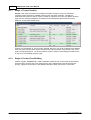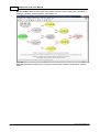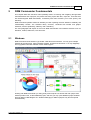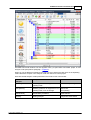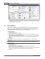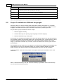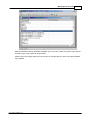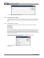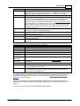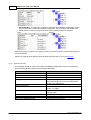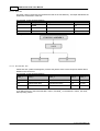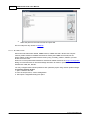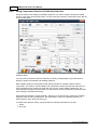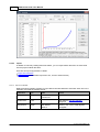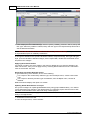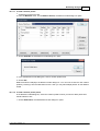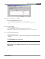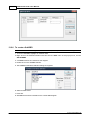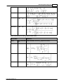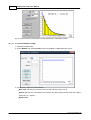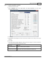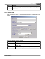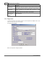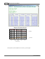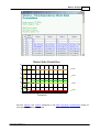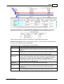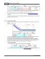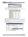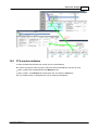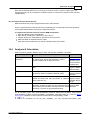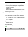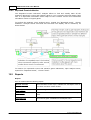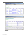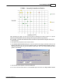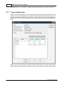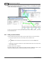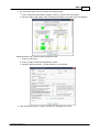
1
RAM Commander User Manual
© 2014 ALD Software Ltd.
RAM Commander User Manual
© 2014 ALD Software Ltd.
All rights reserved. No parts of this work may be reproduced in any form or by any means - graphic, electronic, or
mechanical, including photocopying, recording, taping, or information storage and retrieval systems - without the
written permission of the publisher.
Products that are referred to in this document may be either trademarks and/or registered trademarks of the
respective owners. The publisher and the author make no claim to these trademarks.
While every precaution has been taken in the preparation of this document, the publisher and the author assume no
responsibility for errors or omissions, or for damages resulting from the use of information contained in this
document or from the use of programs and source code that may accompany it. In no event shall the publisher and
the author be liable for any loss of profit or any other commercial damage caused or alleged to have been caused
directly or indirectly by this document.
Printed: 2014
Publisher:
ALD Software Ltd.
Pazgaz Building,
Entrance D, 2nd Floor.
46 Maccabim Road,
Rishon-le-Zion, 7535986, Israel
Phone: + 972 3 7913200
Fax:
+ 972 3 7913210
E-mail: [email protected]
Web: www.aldservice.com
www.aldsoftware.com
The information in this document is subject to change without prior
notice and does not represent a commitment on the part of
Advanced Logistics Developments Ltd. (A.L.D.).
No part of this document may be used or reproduced in any manner
whatsoever without written permission from Advanced Logistics
Developments Ltd. (A.L.D.).
The software described in this document is furnished under a
license agreement or non-disclosure agreement. The software may
be used or copied only in accordance with the terms of the
agreement. It is against the law to copy the ALD Software Tools on
cassette tape, disk or any other medium for any purpose other than
the purchaser’s personal use.
Copyright 1995-2014 by Advanced Logistics Developments Ltd.
MS-DOS and Windows are registered trademark s of Microsoft
Corporation
Any other references to a trademark and/or copyrighted material are
unintentional.
Generated by EC Software - HELP & MANUAL tool.
Contents
3
Table of Contents
Foreword
0
Part 1 Welcome to RAM Commander
16
Part 2 Introduction
18
1 RAM
...................................................................................................................................
Commander History
19
2 Modules
...................................................................................................................................
Overview
20
3 Useful
...................................................................................................................................
Features
21
4 Technical
...................................................................................................................................
Overview
22
5 What
...................................................................................................................................
you need to know
23
6 Getting
...................................................................................................................................
Help
23
Part 3 Getting Started
26
1 Introduction
................................................................................................................................... 26
2 Editions
................................................................................................................................... 29
3 Installation
................................................................................................................................... 29
Installation
.........................................................................................................................................................
Reqiuirem ents
30
Standalone
.........................................................................................................................................................
Installation
31
Netw ork Installation
......................................................................................................................................................... 37
Server Installation
.................................................................................................................................................. 37
Workstation
..................................................................................................................................................
Installation
44
Standalone
.........................................................................................................................................................
Installation + Com m on Netw ork Database
50
Multiple versions
......................................................................................................................................................... 52
4 Licensing
................................................................................................................................... 56
Local USB.........................................................................................................................................................
plug
56
Updating plug
..................................................................................................................................................
configuration
56
Reporting plug
..................................................................................................................................................
configuration
57
Netw ork USB
.........................................................................................................................................................
plug
58
Local License
.........................................................................................................................................................
File
60
Deleting license
.................................................................................................................................................. 62
Sending License
..................................................................................................................................................
Report
64
Netw ork License
.........................................................................................................................................................
File
65
5 Running
...................................................................................................................................
RAM Commander
73
6 Major
...................................................................................................................................
Upgrade
75
Standalone
.........................................................................................................................................................
Configuration - Upgrade
75
Netw ork Configuration
.........................................................................................................................................................
- Upgrade
77
7 Minor
...................................................................................................................................
Update
80
8 Uninstall
...................................................................................................................................
or Modify
80
9 Install
...................................................................................................................................
Component Library
81
10 Administration
................................................................................................................................... 82
Users Managem
.........................................................................................................................................................
ent
83
Projects Managem
.........................................................................................................................................................
ent
85
Libraries and
.........................................................................................................................................................
Defaults Managem ent
86
© 2014 ALD Software Ltd.
4
RAM Commander User Manual
Settings Managem
.........................................................................................................................................................
ent
86
User authentication
..................................................................................................................................................
using AD/LDAP
88
User Activity
.........................................................................................................................................................
Log
89
11 Troubleshooting
................................................................................................................................... 89
Installation
......................................................................................................................................................... 90
Licensing.........................................................................................................................................................
and Plugs
92
Access to.........................................................................................................................................................
Data
94
Reporting
......................................................................................................................................................... 100
General Problem
.........................................................................................................................................................
s
101
12 Summary
................................................................................................................................... 101
Part 4 RAM Commander Concepts
103
1 RAM
...................................................................................................................................
Commander Process
103
Stage
Stage
Stage
Stage
Stage
Stage
Stage
Stage
Stage
1: Project
.........................................................................................................................................................
Creation
106
2: Product
.........................................................................................................................................................
Tree Building
106
3: Reliability
.........................................................................................................................................................
and Maintainability Calculations
107
4: Reliability
.........................................................................................................................................................
Analysis
108
5: Reliability
.........................................................................................................................................................
and Availability Modeling
109
6: Failure
.........................................................................................................................................................
Analysis
111
7: Safety
.........................................................................................................................................................
Analysis
113
8: Additional
.........................................................................................................................................................
Analysis Types
113
9: Next
.........................................................................................................................................................
steps/recurrent analysis
113
2 RAM
...................................................................................................................................
Commander Data Flow
114
3 RAM
...................................................................................................................................
Commander Data Organization
114
4 Summary
................................................................................................................................... 115
Part 5 RAM Commander Fundamentals
117
1 Windows
................................................................................................................................... 117
2 Toolbar
................................................................................................................................... 118
3 Status
...................................................................................................................................
Bar
119
4 Lists
................................................................................................................................... 119
5 Projects
................................................................................................................................... 120
6 Product
...................................................................................................................................
Tree View
122
7 Reports
................................................................................................................................... 126
Text Reports
......................................................................................................................................................... 126
Customization
.................................................................................................................................................. 128
View Stored
..................................................................................................................................................
Reports
129
Report Generator
......................................................................................................................................................... 130
Reports by
.........................................................................................................................................................
MS Word Tem plate
133
Graphs ......................................................................................................................................................... 137
8 Data
...................................................................................................................................
Exchange
138
9 Spelling
...................................................................................................................................
checker
139
Part 6 Working with Projects
142
1 Projects
...................................................................................................................................
list
142
Working .........................................................................................................................................................
w ith the project list
143
2 Mult-iuser
...................................................................................................................................
access
144
© 2014 ALD Software Ltd.
Contents
5
3 Creating
...................................................................................................................................
a new project
146
4 Managing
...................................................................................................................................
permissions
147
Advanced
.........................................................................................................................................................
Perm issions
148
5 Opening
...................................................................................................................................
project
150
6 Backup/Restore
................................................................................................................................... 152
7 Project
...................................................................................................................................
copies/revisions
153
8 Additional
...................................................................................................................................
Operations
153
9 Project
...................................................................................................................................
Translation to Different Languages
154
Part 7 Product Tree
157
1 Activating
...................................................................................................................................
the Product Tree View
158
2 Product
...................................................................................................................................
Tree Navigation
158
Selecting.........................................................................................................................................................
Current Analysis
158
Expanding
.........................................................................................................................................................
and Collapsing
160
Opening .........................................................................................................................................................
item s
160
Search ......................................................................................................................................................... 160
Changing.........................................................................................................................................................
tree presentation
162
Changing..................................................................................................................................................
"Name" of tree items
162
Custom tree
..................................................................................................................................................
fields
163
Normal/Functional
..................................................................................................................................................
View
164
3 Product
...................................................................................................................................
Tree Building
164
Project Configuration
......................................................................................................................................................... 164
Top item.........................................................................................................................................................
definition
165
New item.........................................................................................................................................................
creation
167
New item..................................................................................................................................................
defaults
168
Quick Create
.................................................................................................................................................. 169
Item data.........................................................................................................................................................
editing
169
Environment
..................................................................................................................................................
and Temperature Definition
172
Standard..................................................................................................................................................
Environments
174
Additional
.........................................................................................................................................................
operations w ith item s
175
Deleting items
.................................................................................................................................................. 175
Copy/Move
..................................................................................................................................................
items
175
Global Change
.................................................................................................................................................. 176
Massive Entry
.................................................................................................................................................. 178
To open the
...........................................................................................................................................
Massive Entry list
179
To add new
...........................................................................................................................................
items in a Massive Entry list
179
Additional...........................................................................................................................................
operations w ith the list
180
Count Parts
...........................................................................................................................................
Utility
181
Massive Entry
...........................................................................................................................................
Reports
182
Copy betw
..................................................................................................................................................
een fields
182
Marking w..................................................................................................................................................
ith Colors
183
Organize.................................................................................................................................................. 183
4 Import/Export
................................................................................................................................... 184
Im port Wizard
......................................................................................................................................................... 184
Step 1 .................................................................................................................................................. 185
Step 2 - Text
..................................................................................................................................................
files
186
Step 3 - Text
..................................................................................................................................................
files
187
Step 2 - Mentor
..................................................................................................................................................
Graphics
187
Step 2 - Excel/Access
..................................................................................................................................................
files
188
Troubleshooting
........................................................................................................................................... 188
© 2014 ALD Software Ltd.
6
RAM Commander User Manual
Step 3/4 -..................................................................................................................................................
Mapping
190
Database...........................................................................................................................................
Fields Index
192
Item Code...........................................................................................................................................
abbreviations
195
Depth field........................................................................................................................................... 200
Parent Ref.Des.
...........................................................................................................................................
field
200
Hierarchical
...........................................................................................................................................
Parent Ref.Des. field
201
Stress ........................................................................................................................................... 202
Search in...........................................................................................................................................
Library
205
Level of replace/repair
........................................................................................................................................... 205
Failure Rate
...........................................................................................................................................
source sw itch
206
MCT/MLH...........................................................................................................................................
source sw itch
206
Step 4/5 -..................................................................................................................................................
Finish
206
Using Import
..................................................................................................................................................
Wizard for tree update
207
Export ......................................................................................................................................................... 207
5 Reports
................................................................................................................................... 208
Part 8 Reliability Calculation
211
1 Configurating
...................................................................................................................................
Reliability Module
212
Operating
.........................................................................................................................................................
vs Non-Operating Mode
212
Choosing.........................................................................................................................................................
suitable Reliability Prediction Method
212
2 Item
...................................................................................................................................
FR Calculation
215
Com ponent
.........................................................................................................................................................
Failure Rate prediction
217
Special Fields
..................................................................................................................................................
in the Prediction Method Screens
220
Junction Temperature
........................................................................................................................................... 220
Stress values
........................................................................................................................................... 221
Method-Specific
..................................................................................................................................................
features
222
NPRD-95 ........................................................................................................................................... 222
NPRD-2011
........................................................................................................................................... 224
IEC, FIDES,
...........................................................................................................................................
217Plus
226
FIDES 2009
........................................................................................................................................... 228
Non-Operating
...........................................................................................................................................
MIL-HDBK-217E
233
Notes on Environments
...........................................................................................................................................
and Methods
235
Stress/Strength
........................................................................................................................................... 236
Hybrid and
...........................................................................................................................................
Substrate
238
Specify know
.........................................................................................................................................................
n fixed FR
239
Specify know
.........................................................................................................................................................
n tem perature-dependent FR
240
Failure Rate
.........................................................................................................................................................
Allocation
241
3 Project
...................................................................................................................................
Recalculation
242
Log File ......................................................................................................................................................... 243
4 Reports
................................................................................................................................... 243
Part 9 Reliability Libraries and Defaults
246
1 Global
...................................................................................................................................
and Project Libraries
247
2 Component
...................................................................................................................................
Library
248
To view the
.........................................................................................................................................................
project com ponent library
249
To view the
.........................................................................................................................................................
global com ponent library
249
Working .........................................................................................................................................................
w ith the Com ponent Library
250
To edit component
..................................................................................................................................................
data
251
To delete..................................................................................................................................................
component from the library
251
To insert ..................................................................................................................................................
new component into the library
251
To find component
.................................................................................................................................................. 251
© 2014 ALD Software Ltd.
Contents
7
Transfer ..................................................................................................................................................
data from a project to global library
252
Reports ......................................................................................................................................................... 252
Data Im port
......................................................................................................................................................... 253
Using Com
.........................................................................................................................................................
ponent Libraries in Reliability Prediction
256
Retrieve or
..................................................................................................................................................
save single component data
257
Load from
..................................................................................................................................................
Library
258
Load to Library
.................................................................................................................................................. 259
3 Cross-Reference
................................................................................................................................... 259
Using Cross-Reference
.........................................................................................................................................................
Library in Reliability Prediction
261
Data Im port
......................................................................................................................................................... 264
4 Part
...................................................................................................................................
Number Recognition
264
5 GPRD
................................................................................................................................... 265
Entering .........................................................................................................................................................
the GPRD Library
266
General Part
.........................................................................................................................................................
Data
267
FMECA data
......................................................................................................................................................... 268
Field Failure
.........................................................................................................................................................
Rate Tables
268
Manual FR
..................................................................................................................................................
Table Data Entry
269
Pack to Box
.................................................................................................................................................. 270
Import .................................................................................................................................................. 272
Import from
...........................................................................................................................................
ASCII file
272
Import Wizard
........................................................................................................................................... 273
Copying and
..................................................................................................................................................
Deleting Failure Rate Tables
274
Using GPRD
..................................................................................................................................................
Library in Reliability Prediction
274
Failure Rate
..................................................................................................................................................
Table Formulae
275
Copying GPRD
.........................................................................................................................................................
Library betw een projects
277
Reports ......................................................................................................................................................... 277
6 Calculation
...................................................................................................................................
Defaults
278
7 Managing
...................................................................................................................................
Libraries
282
Copy libraries
.........................................................................................................................................................
betw een projects
282
Global Library
.........................................................................................................................................................
Files Location
283
Back Up and
.........................................................................................................................................................
Restore of Global Libraries
283
Part 10 Reliability Analysis
286
1 Temperature
...................................................................................................................................
Curve
286
2 Pareto
................................................................................................................................... 287
3 Mission
...................................................................................................................................
Profile
289
Defining a
.........................................................................................................................................................
Mission Profile
290
To add a ..................................................................................................................................................
mission profile
291
To add a ..................................................................................................................................................
mission profile phase
291
To delete..................................................................................................................................................
a mission profile phase
292
To copy a..................................................................................................................................................
mission profile
293
To delete..................................................................................................................................................
a mission profile
293
Mission Profile
.........................................................................................................................................................
Calculation
293
Sum m ary......................................................................................................................................................... 295
4 Burn-In
...................................................................................................................................
Report
295
Part 11 Maintainability Prediction
297
1 Philosophy
...................................................................................................................................
and Assumptions
297
Inform ation
.........................................................................................................................................................
Required
298
2 Maintainability
...................................................................................................................................
Prediction Modeling
298
© 2014 ALD Software Ltd.
8
RAM Commander User Manual
Maintenance
.........................................................................................................................................................
Corrective Tim e
299
Mean Tim.........................................................................................................................................................
e to Repair
299
Am biguity
.........................................................................................................................................................
Factor
300
Maxim um.........................................................................................................................................................
Corrective Maintenance Tim e
301
Mean Maintenance
.........................................................................................................................................................
Man-hours per Maintenance Action
301
Maintainability
.........................................................................................................................................................
Allocation
302
3 Preliminary
...................................................................................................................................
Steps
303
Custom ize
.........................................................................................................................................................
Organizational Levels
303
Set Mct m
.........................................................................................................................................................
ax Calculation Method
304
4 Performing
...................................................................................................................................
Maintainability Analysis
307
To enter .........................................................................................................................................................
Mct data
308
MIL-HDBK-472
.........................................................................................................................................................
Procedure 5A
309
To define..................................................................................................................................................
MIL-472 Procedure 5A maintainability task information
310
MIL-472 Procedure
..................................................................................................................................................
5 Task Definition
313
To define ...........................................................................................................................................
a tasks using user-defined times
313
To retrieve
...........................................................................................................................................
a standard time from the standard times library
313
To retrieve
...........................................................................................................................................
a standard task from the task library
314
To define ...........................................................................................................................................
a task’s maintenance data
314
Mean Tim.........................................................................................................................................................
e To Repair - MTTR
315
To compute
..................................................................................................................................................
MTTR
315
To calculate
...........................................................................................................................................
MTTR and Mct in Quick mode
315
Recalculate
..................................................................................................................................................
All
316
To calculate
...........................................................................................................................................
MTTR and Mct in Recalculate All mode
316
Fault Isolation
..................................................................................................................................................
and Ambiguity
316
Maintainability
.........................................................................................................................................................
Allocation
317
To perform
..................................................................................................................................................
maintainability allocation
317
To copy maintainability
...........................................................................................................................................
tasks data to other items
317
5 Maintainability
...................................................................................................................................
Libraries
317
To access
.........................................................................................................................................................
the Standard Tim es Library
319
To add or..................................................................................................................................................
edit a record in the Standard Times Library
319
To delete..................................................................................................................................................
a record in the Standard Times Library
320
To access
.........................................................................................................................................................
the Standard Tasks Library
320
To add a ..................................................................................................................................................
new task to the Standard Tasks Library
320
To delete..................................................................................................................................................
a task from the Standard Tasks Library
320
To edit a ..................................................................................................................................................
task in the Standard Tasks Library
321
Standard.........................................................................................................................................................
Tasks/Tim es Library Reports
321
To access
.........................................................................................................................................................
the Maintenance Library
321
6 Maintainability
...................................................................................................................................
Reports
322
7 RCM
...................................................................................................................................
Module
323
8 Summary
................................................................................................................................... 326
Part 12 Derating/Stress Analysis
328
1 Defining
...................................................................................................................................
Derating Guidelines
329
To define.........................................................................................................................................................
Derating Guidelines
330
Print Derating
.........................................................................................................................................................
Guidelines
333
2 Entering
...................................................................................................................................
Actual Stress Values
334
3 Derating
...................................................................................................................................
Reports
336
4 Summary
................................................................................................................................... 338
Part 13 Reliability Block Diagrams
340
© 2014 ALD Software Ltd.
Contents
9
1 RBD
...................................................................................................................................
Basics
341
2 Drawing
...................................................................................................................................
the Diagram
342
To create.........................................................................................................................................................
a new RBD diagram
342
To change
.........................................................................................................................................................
an RBD configuration
343
To add an.........................................................................................................................................................
elem ent to an RBD
344
To enter .........................................................................................................................................................
data for an RBD elem ent
344
K/N Elem ent
.........................................................................................................................................................
Configuration
346
To create.........................................................................................................................................................
a SubRBD
348
To delete.........................................................................................................................................................
an RBD elem ent
349
Saving and
.........................................................................................................................................................
Opening Reliability Block Diagram s
349
Working .........................................................................................................................................................
w ith Diagram s
349
Elements ..................................................................................................................................................
Color
349
To fold a ..................................................................................................................................................
series of RBD elements to fit the screen
350
To zoom ..................................................................................................................................................
in or out of an RBD
351
To copy an
..................................................................................................................................................
RBD element
352
Update RBD
..................................................................................................................................................
Information
352
Export to..................................................................................................................................................
MEADEP
352
Export to..................................................................................................................................................
MS Word, Excel etc.
352
Global Changes
.................................................................................................................................................. 353
3 RBD
...................................................................................................................................
Calculations
354
To calculate
.........................................................................................................................................................
an RBD
354
Form ulas......................................................................................................................................................... 355
Reliability..................................................................................................................................................
Distributions
355
Availability
..................................................................................................................................................
Distributions
356
Basic calculations
.................................................................................................................................................. 357
K-out-of-N
..................................................................................................................................................
With Repair
358
K-out-of-N
..................................................................................................................................................
Without Repair
361
Equivalent
..................................................................................................................................................
Lambda/MTBF
361
MTBCF and
.........................................................................................................................................................
R(t)
362
To calculate
..................................................................................................................................................
MTBCF and R(t)
364
Monte Carlo
.........................................................................................................................................................
Sim ulations
365
To initiate..................................................................................................................................................
a Monte Carlo simulation
366
4 RBD
...................................................................................................................................
Reports
368
5 Summary
................................................................................................................................... 369
Part 14 System Configuration
371
1 To
...................................................................................................................................
open the configuration system list
371
2 To
...................................................................................................................................
create a new configuration
372
3 Adding
...................................................................................................................................
Blocks to Configuration
373
4 Working
...................................................................................................................................
with existing configurations
374
To update
.........................................................................................................................................................
RAM info
374
To delete.........................................................................................................................................................
an item
375
To locate.........................................................................................................................................................
an item in a tree
375
To reorder
.........................................................................................................................................................
item s inside the Configuration
375
To edit an
.........................................................................................................................................................
item
375
5 RBD
...................................................................................................................................
diagram building
376
6 MTBCF
...................................................................................................................................
Calculation
377
7 Reports
................................................................................................................................... 377
8 Summary
................................................................................................................................... 378
© 2014 ALD Software Ltd.
10
RAM Commander User Manual
Part 15 Reliability Growth
380
1 Reliability
...................................................................................................................................
Growth Modeling
381
2 To
...................................................................................................................................
view reliability growth data
383
3 To
...................................................................................................................................
enter reliability growth data
383
4 To
...................................................................................................................................
compute reliability growth planning parameters
384
5 Reliability
...................................................................................................................................
Growth Formula
386
6 Reliability
...................................................................................................................................
Growth Reports
386
To generate
.........................................................................................................................................................
reliability grow th reports
387
7 Summary
................................................................................................................................... 389
Part 16 Spare Parts Analysis
391
1 Operation
...................................................................................................................................
Modes
391
2 Product
...................................................................................................................................
Tree Data
391
3 Spare
...................................................................................................................................
Parts Calculation
392
To add an.........................................................................................................................................................
operation scenario
393
Working .........................................................................................................................................................
w ith existing Scenarios
394
To copy a..................................................................................................................................................
spare parts operation scenario
394
To delete..................................................................................................................................................
a scenario
394
To edit a ..................................................................................................................................................
scenario
395
Generating
.........................................................................................................................................................
Spare Parts Reports
395
4 Spare
...................................................................................................................................
Parts Optimization
395
Optim ization
.........................................................................................................................................................
CriteriaThe spare parts m odule supports the com putation of tw o optim ization criteria:
396
Constraint
......................................................................................................................................................... 396
Optim ization
.........................................................................................................................................................
Algorithm
397
Optim ization
.........................................................................................................................................................
Param eters
397
To set operation
..................................................................................................................................................
scenario parameters
397
Generating
.........................................................................................................................................................
Optim ization Reports
399
To generate
..................................................................................................................................................
an optimization report
399
To review..................................................................................................................................................
optimal spare part quantities
401
5 Spare
...................................................................................................................................
Parts Analysis Formulae
403
6 Possible
...................................................................................................................................
Important Applications
403
Com pound
.........................................................................................................................................................
Operation Modes
403
Spares and
.........................................................................................................................................................
Level of Repair Decisions
404
7 Summary
................................................................................................................................... 404
Part 17 Markov Analysis
406
1 Initiating
...................................................................................................................................
Markov module
407
2 Drawing
...................................................................................................................................
the diagram
408
Draw a state
......................................................................................................................................................... 408
Draw a Transition
......................................................................................................................................................... 409
State Data
......................................................................................................................................................... 410
Transition
.........................................................................................................................................................
Data
411
Diagram data
......................................................................................................................................................... 412
Working .........................................................................................................................................................
w ith diagram
413
3 Calculation
................................................................................................................................... 413
4 Reports
................................................................................................................................... 414
© 2014 ALD Software Ltd.
Contents
Part 18 FMECA
11
422
1 Initiating
...................................................................................................................................
FMECA module
423
2 FMECA
...................................................................................................................................
Module Basics
424
3 Configurating
...................................................................................................................................
FMECA module
426
FMEA or FMECA
......................................................................................................................................................... 426
FMECA Library
......................................................................................................................................................... 427
FMECA Grid
.........................................................................................................................................................
Custom ization
428
Phase selection
......................................................................................................................................................... 429
4 FMECA
...................................................................................................................................
Libraries
430
To access
.........................................................................................................................................................
FMECA libraries
431
FMECA Libraries
.........................................................................................................................................................
Definition
431
Generating
.........................................................................................................................................................
a Library Report
432
Global Change
.........................................................................................................................................................
of the End Effect Library
432
Copy FMECA
.........................................................................................................................................................
Libraries Betw een Projects
432
5 Entering
...................................................................................................................................
FMECA data for Item
433
Entering .........................................................................................................................................................
Next Higher Effects
435
To define..................................................................................................................................................
a single NHE
436
To select..................................................................................................................................................
affected assembly
437
To define..................................................................................................................................................
multiple NHEs for a single FM
437
To define..................................................................................................................................................
NHE for NHE
438
Additional
.........................................................................................................................................................
operations in FMECA grid
440
FM Column
..................................................................................................................................................
Pop-up Menu Options
441
Alpha Column
..................................................................................................................................................
Pop-up Menu Options
442
NHE Column
..................................................................................................................................................
Pop-up Menu Options
443
End Effect
..................................................................................................................................................
Column Pop-up Menu Options
443
6 Testability
...................................................................................................................................
Analysis Module (TAM)
444
To define.........................................................................................................................................................
tests for FM
444
Testability
.........................................................................................................................................................
Analysis Reports
446
7 Functional
...................................................................................................................................
Blocks
448
To create.........................................................................................................................................................
functional blocks
449
Working .........................................................................................................................................................
w ith Functional Blocks
451
8 FMECA
...................................................................................................................................
Reports
451
To Generate
.........................................................................................................................................................
an FMECA Report
453
9 Import/Export
................................................................................................................................... 453
Functional
.........................................................................................................................................................
Blocks Im port
456
10 Summary
................................................................................................................................... 457
Part 19 Fault Tree Analysis
459
1 FTA
...................................................................................................................................
basics
460
2 FTA
...................................................................................................................................
module initiation
463
3 Building
...................................................................................................................................
FTA Diagrams
464
Creating .........................................................................................................................................................
a new Fault Tree
465
Define FTA
.........................................................................................................................................................
properties
465
FTA diagram
.........................................................................................................................................................
building
467
Transfers
......................................................................................................................................................... 469
Events library
......................................................................................................................................................... 469
Delete elem
.........................................................................................................................................................
ents
470
Copy & Paste
......................................................................................................................................................... 471
© 2014 ALD Software Ltd.
12
RAM Commander User Manual
Rem arks......................................................................................................................................................... 472
Autom atic
.........................................................................................................................................................
FTA building
473
Print preview
.........................................................................................................................................................
, Print, Zoom
473
Export Diagram
.........................................................................................................................................................
as Picture
473
Using Com
.........................................................................................................................................................
m on Cause Failures
474
Gobal Change
......................................................................................................................................................... 475
Im porting
.........................................................................................................................................................
Fault Trees
478
Import FT..................................................................................................................................................
from RiskSpectrum
478
Import FT..................................................................................................................................................
from Isograph FT+
478
Import FT..................................................................................................................................................
from CAFTA
480
Import FT..................................................................................................................................................
from Aralia Simtree
481
4 Analysis
...................................................................................................................................
& Calculation
481
Basic Event
.........................................................................................................................................................
Types
482
MCS Calculation
......................................................................................................................................................... 484
Tree Unavailability
..................................................................................................................................................
calculation
487
Easary-Proschan
..................................................................................................................................................
Formula
487
Frequency
..................................................................................................................................................
W(t) Calculation
488
PFH and PFD
..................................................................................................................................................
Calculation
488
Lambda Equivalent
.................................................................................................................................................. 489
House Event
.........................................................................................................................................................
Profiles
489
Im portance
.........................................................................................................................................................
/ Sensitivity Analysis
490
FALSE/TRUE
.........................................................................................................................................................
Propagation
491
Repeated.........................................................................................................................................................
Events Indication
494
5 Reports
................................................................................................................................... 494
6 Summary
................................................................................................................................... 495
Part 20 Event Tree Analysis
497
1 ETA
...................................................................................................................................
module initiation
498
2 ETA
...................................................................................................................................
diagram building
500
Events library
......................................................................................................................................................... 503
Delete ......................................................................................................................................................... 504
Export Diagram
.........................................................................................................................................................
as Picture
504
Print preview
.........................................................................................................................................................
, Print, Zoom
504
3 Analysis
...................................................................................................................................
& Calculation
504
4 Reports
................................................................................................................................... 504
5 Summary
................................................................................................................................... 506
Part 21 Process/Design FMEA
508
1 FMEA
...................................................................................................................................
Basics
509
2 FMEA
...................................................................................................................................
module initiation
510
3 Defining
...................................................................................................................................
FMEA Properties
511
4 Drawing
...................................................................................................................................
the Diagram
512
Draw ing a
.........................................................................................................................................................
Node
512
Draw ing a
.........................................................................................................................................................
Link
513
Multiselection
......................................................................................................................................................... 513
Stretching
.........................................................................................................................................................
a Link
514
Draw ing a
.........................................................................................................................................................
Reflexive Link
514
Delete ......................................................................................................................................................... 514
Copy & Paste
......................................................................................................................................................... 515
© 2014 ALD Software Ltd.
Contents
13
Sub-diagram
.........................................................................................................................................................
s
515
Print, Zoom
.........................................................................................................................................................
, Undo
516
Export Diagram
.........................................................................................................................................................
as Picture
516
Inserting.........................................................................................................................................................
nodes from Product Tree
516
5 Failure
...................................................................................................................................
Modes, Causes and Effects
516
To create.........................................................................................................................................................
a new Failure Mode
517
To create.........................................................................................................................................................
a new Failure Cause
518
To edit or.........................................................................................................................................................
delete Failure Modes
519
To copy failure
.........................................................................................................................................................
m ode
519
Spelling checker
......................................................................................................................................................... 519
To w ork .........................................................................................................................................................
w ith cum ulative list of failures
520
6 Selecting
...................................................................................................................................
Critical Failure Causes
521
7 Team
...................................................................................................................................
Collaboration
524
To define.........................................................................................................................................................
the expert team
525
To collect.........................................................................................................................................................
rankings m anually
525
To collect.........................................................................................................................................................
rankings autom atically
526
Voting System
.........................................................................................................................................................
Installation
526
To install ..................................................................................................................................................
and configure the Voting System
527
8 Making
...................................................................................................................................
Decisions on Corrective Action
529
9 Libraries
................................................................................................................................... 531
To view and
.........................................................................................................................................................
update FMEA libraries
532
To update
.........................................................................................................................................................
a library during FMEA data input
532
To select.........................................................................................................................................................
a field value from a library
533
To copy libraries
.........................................................................................................................................................
betw een projects
533
Load to Library
......................................................................................................................................................... 534
10 Reports
................................................................................................................................... 534
To print the
.........................................................................................................................................................
report
536
11 Summary
................................................................................................................................... 536
Part 22 Safety Analysis
538
1 Safety
...................................................................................................................................
Module Basics
538
2 Safety
...................................................................................................................................
module initiation
540
3 Safety
...................................................................................................................................
Libraries
541
Working .........................................................................................................................................................
w ith Libraries
541
4 Building
...................................................................................................................................
the Functional Tree
543
5 Working
...................................................................................................................................
with different standards/recommendations
545
6 Working
...................................................................................................................................
with Failure Conditions
546
7 Probability
...................................................................................................................................
Calculation
551
8 Reports
................................................................................................................................... 551
Part 23 MMEL
556
1 Prerequisites
...................................................................................................................................
for MMEL generation using RAM Commander MMEL Module
556
2 MMEL
...................................................................................................................................
Analysis process
557
3 To
...................................................................................................................................
perform MMEL analysis
557
4 1st
...................................................................................................................................
step: MMEL Quantitative Analysis
560
MMEL Module
.........................................................................................................................................................
Quantitative Analysis Algorithm
560
To select.........................................................................................................................................................
a required algorithm
562
© 2014 ALD Software Ltd.
14
RAM Commander User Manual
To activate
.........................................................................................................................................................
quantitative analysis
563
5 2nd
...................................................................................................................................
step: MMEL Five Column Format Report Preparation
565
6 MMEL
...................................................................................................................................
Module Reports
566
7 Summary
................................................................................................................................... 569
Part 24 MSG-3
571
1 Systems
...................................................................................................................................
and Power Plant Analysis
571
Initiating .........................................................................................................................................................
MSG-3 Module
572
MSG-3 Procedure
.........................................................................................................................................................
Steps
572
Step 1 – System
..................................................................................................................................................
Definition
572
Step 2 – MSI
..................................................................................................................................................
Selection
573
Step 3 – FMECA
.................................................................................................................................................. 575
Step 4 – Failure
..................................................................................................................................................
Effect Categorization
576
Step 5 – Task
..................................................................................................................................................
Selection
578
Step 6 – Task
..................................................................................................................................................
Interval
579
Step 7 – MSG-3
..................................................................................................................................................
Report
580
2 Structural
...................................................................................................................................
Analysis
582
3 Zonal
...................................................................................................................................
Analysis
583
4 L/HIRF
...................................................................................................................................
Analysis
584
Index
586
© 2014 ALD Software Ltd.
Chapter
1
Welcome to RAM
Commander
16
1
RAM Commander User Manual
Welcome to RAM Commander
RAM Commander is the pioneering Reliability and Safety software for reliability professionals and
design engineers, developed by the ALD Reliability and Safety Solutions. RAM Commander
combines ingenuity of approach, calculation accuracy, convenience of use. Designed by reliability
engineers, RAM Commander covers the entire scope of engineering tasks related to reliability of
electronic, electro-mechanical and mechanical systems.
List of RAM Commander modules contains Reliability, Maintainability, RBD, Fault Tree Analysis,
Event Tree Analysis, Safety Assessment, Spare Parts optimization, Derating, FMECA and
Testability Analysis, Process&Design FMEA, FTA and more.
This manual is designed as installation and upgrade guide for IT staff, course in using RAMC for new
users and ongoing reference to program functions for users already working with the software.
© 2014 ALD Software Ltd.
Chapter
2
Introduction
18
2
RAM Commander User Manual
Introduction
This chapter tells you about RAM Commander, its purpose, its history and useful features.
RAM Commander (Reliability, Availability, Maintainability Prediction and Analysis) is a 32-bit
integrated LAN-compatible Windows software package for:
System structure definition, graphical presentation and impact;
Reliability, availability, and maintainability prediction;
Reliability and maintainability allocation with user-defined complexity factors;
Reliability and maintainability parameter trade-offs and optimization in accordance with
multiple mission profile definitions such as environment, temperature and phase times for
operating and non-operating phases;
Building, maintaining and evaluating functional reliability block diagrams using a graphical
interface;
Reliability and availability estimation for a multitude of graphically presented system
configurations.
A definition of derating guidelines and an analysis of the overstressed components;
Spare parts quantity estimation and optimizations;
Failure modes and effects criticality analysis (FMECA);
Testability analysis;
Process and Design FMEA;
Fault Tree Analysis
Event Tree Analysis
Markov Chains Analysis
Safety Analysis (including FHA, SSA, PHA, MMEL, SHA)
MSG-3 Analysis
Automatic data validation and correction;
Generating professional reports.
The partial list of RAM Commander customers is provided below:
© 2014 ALD Software Ltd.
Introduction
2.1
19
RAM Commander History
In 1988, ALD released the first DOS version of reliability software called RPTB. In 1992, RAM
Commander for DOS was released followed by the Windows version in late 1995. In 1998, Spares
Optimization, derating modules and Monte-Carlo simulation modules were added. Since then, RAM
Commander has quickly become the world’s leading software in the area of reliability and
maintainability prediction with the fully integrated FMECA and design/process FMEA. You will not
find another R&M software package providing all the modules, options, interface and quality
documentation that RAM Commander does.
RAM Commander history milestones:
1995 - RAM Commander 6.0 for Windows replaces the RPTB
1998 - Spares Optimization, Derating Modules and Monte-Carlo Simulation modules
1999 - RAM Commander 7.0, the 32-bit version is released
2001 - Fully integrated FMECA and design/process FMEA
2002 - Functional FMECA, ILS support and NSWC
2003 - Integrated Fault Tree Analysis and Siemens prediction method
2004 - Integrated Safety module and FIDES prediction method
2005 - Multi-user work support and IEC 62380 prediction method
2006 - Stress/Strength Analysis, Siemens SN 29500-2005-1 and HTML reports
2006 - Event Trees, FMECA report generator and RCM
2007 - Markov Analysis, Telcordia Issue 2, 217Plus and multilingual database support
2008 - MMEL (Master Minimum Equipment List) Module
© 2014 ALD Software Ltd.
20
RAM Commander User Manual
2009 - MSG-3, faster FTA calculation and advanced security
2010 - New look, FIDES 2009 and reports by MS Word template
2011 - MSG-3 Structural, Zonal and L/HIRF Analysis
2013 - Telcordia Issue 3, NPRD-2011, Binary Decision Diagrams
2014 - UI face-lift, FIDES 2009 Part count and Family count methods, FDAL allocation support
To maintain our competitive edge, we have been collecting customer responses and questions. In
addition, we have added many new functions to keep RAM Commander current with state-of-the-art
technologies.
As always, ALD is interested to know how you use RAM Commander. If you have any special
applications or hints, or have come across any particular problems, do not hesitate to write us at the
addresses listed in the Getting Help section of this manual or use our ALD Software Feedback Form
.
2.2
Modules Overview
RAM Commander is the pioneering Reliability and Safety software for reliability professionals and
design engineers. RAM Commander combines ingenuity of approach, calculation accuracy,
convenience of use. Designed by reliability engineers, RAM Commander covers the entire scope of
engineering tasks related to reliability of electronic, electro-mechanical and mechanical systems.
RAM Commander is modular software allowing a customer the flexibility of gradual addition of the
modules to the package in accordance with the requirements of a project or the budget constraints.
List of RAM Commander modules contains Reliability, Maintainability, RBD, Fault Tree Analysis,
Event Tree Analysis, Safety Assessment, Spare Parts optimization, Derating, FMECA and
Testability Analysis, Process&Design FMEA and more.
Table below provides
Module
Basic (Reliability
Prediction and
Analysis)
Import Wizard
Report Generator
RBD
Markov
Maintainability
Prediction
Spare parts
Derating/Stress
Analysis
brief information about software modules:
Description
Reliability Calculation for Operating and Non-operating state, using more than
25 reliability prediction standards such as MIL-STD-217, FIDES, BELLCORE,
GJB299, Telcordia, NSWC, NPRD-95 and more). Reliability data libraries.
Reliability analysis using reports, Pareto, Temperature Curve, Mission Profile
and more.
Customizable BOM import from ASCII, Access, Excel
Customizable user-defined reports generator for BOM, reliability,
maintainability, FMECA, ILS and more
Reliability Block Diagram analysis module for reliability modelling of serial,
parallel, K-out-of-N (partially loaded, with.without switch, with/without repair)
redundancy configurations. Monte Carlo simulation, MTBCF calculation.
Markov chains analysis for steady-state and time-dependent mode.
Maintainability analysis according to MIL-STD-472 Procedure A, maintenance
analysis, RCM Module, MSG-3
Spare parts calculation and optimization, based on two cost optimization
criteria: Total No Shortage Probability & Availability. Integrated with Reliability
and Maintainability modules.
Analyze overstress of components under current temperature conditions. The
module provides a tool to define Derating curves and identify overstressed
components, i.e., those working under stress exceeding the specified rating
value.
© 2014 ALD Software Ltd.
Introduction
FMECA
Process/Design
FMEA
FTA
ETA
Safety
MMEL
21
Failure Modes, Effects and Criticality Analysis according to MIL-STD-1629
and other standards. Hardware and functional FMECA, Testability Analysis.
Potential Failure Mode and Effects Analysis (FMEA) described by AIAG, QS9000, SAE J 1739, IEC 60812, JEP131 and other standards, sometimes
called "automotive" or "AIAG" (Automotive Industry Action Group) FMEA.
Fault Tree Analysis - builing Fault Trees, Minimal Cut Sets generation and
Unavailability calculation. Integrated with Product tree/Reliability/
Maintainability/FMECA modules.
Event Tree Analysis. Integrated with Product tree/Reliability/Maintainability/
FMECA/FTA modules.
Safety assessment module performing tasks required by safety standards
like SAE ARP 4781, MIL-STD-882 and others. FHA, PHA, SSA, SHA,
O&SHA analysis. Integrated with Product Tree, FMECA and FTA modules.
Master Minimum Equipment List (MMEL) is a document which lists the
equipment that may temporarily be inoperative, subject to certain conditions,
whilst maintaining an acceptable level of safety as intended in the applicable
documents.MMEL analysis is required for all aircraft manufacturers to certify
aircraft safety in different aviation authorities such as FAA, EASA etc.RAM
Commander integrated MMEL module supports Master Minimum Equipment
List generation using Reliability, FMECA, FHA (Safety) and FTA modules
results.
All the modules are integrated into single software package and stored in a single database.
Each RAM Commander project (database) is a briefcase of different analysis types performed by the
modules stated above, for specific product, device or system:
Customer may purchase license for any subset of available modules.
2.3
Useful Features
In addition to the modules and features covering all the scope of RAM analysis, RAM Commander is
supplied with the following useful features:
Extensive set of component libraries - RAM Commander is equipped with an extensive set of
© 2014 ALD Software Ltd.
22
RAM Commander User Manual
libraries for more than 60,000 standard components. You can easily locate devices in the library
and insert them directly into your project.
Importing files from external applications - Do you have an existing product tree on another
application? Use RAM Commander’s import wizard to safely and completely migrate all the data
into RAM Commander’s database.
Copying data between projects - Use RAM Commander’s copy utilities to quickly build new
projects based on previous ones.
Context-sensitive help - Press F1 at any time to view online help about a dialog box, menu or
window.
Multiple windowing - You can open several windows simultaneously, allowing easy access to
information in different sections of one project or in different projects.
Network operation - You can run RAM Commander under LAN, allowing you to install the
software on one computer and making it available to all network users.
Variable access privileges - System managers assign various access levels to RAM
Commander users. You can protect sensitive information and provide the flexibility for easy
information flow between users.
Product tree presentation - Navigating through a project is very similar to navigating through any
commonly used hierarchical structures, such as exploring folders in MS Windows.
Operating data grids - Many of the RAM Commander features use a grid displaying only the
most important fields that allows editing essential data directly on the grid.
Automatic tree recalculation option - There is an option of automatic recalculation when
defining the project properties to ensure that the RAM Commander output is based on the latest
updated data.
Report Generator
Documents Generation using MS Word templates
2.4
Technical Overview
RAM Commander is a 32-bit MS Windows Application which can work in both standalone mode on
a single computer with locally located database and in client/server configuration with common
database located on server. RAM Commander Database contains multiple projects, where each
project is a folder containing all available studies and analysis types (reliability, safety, Fault Trees,
etc.).
Deployment
See Getting Started - Introduction paragraph for more information about installation models.
See also Getting Started - Installation requirements paragraph.
Connectivity
Import/Export data from/to text, CSV, Excel, Access. Flexible import Wizard and Report Generator.
Web services (SOAP) connectivity to FavoWeb FRACAS (RAM Commander calls FavoWeb web
services).
Special format for electronic components library import and reliability data import.
GUI Language
English, Russian, Chinese. Other languages are available on demand.
Licensing
Multiple flexible licensing models - floating network license, computer-locked hardware key,
computer-locked software license and more. See Getting Started - Licensing paragraph for more
information about different licensing models.
© 2014 ALD Software Ltd.
Introduction
23
Technology used
Database: Pervasive SQL + MS Access
Application: Windows application, MFC. Some modules use .NET Framework 2.0. Some modules
use .NET Framework 4.0.
2.5
What you need to know
To effectively operate the RAM Commander, as well as understand concepts presented in this
manual, you need to know the following:
Intermediate user knowledge and skills of Microsoft Windows and Microsoft Office.
Fundamentals of reliability and maintainability prediction modeling.
Depending on module selection, you need to know also theory and practice of such analysis
types as FTA, FMECA, be familiar with specific standards (MIL-STD-1629, SAE ARP 4761
etc.).
With this background, you can start using RAM Commander in a quick and efficient manner.
2.6
Getting Help
There is a number of different sources of information on RAM Commander software.
In addition to this manual you can also access online knowledge base (for registered customers
only - contact ALD Software Technical support for link and access details), online manual at http://
www.aldsoftware.com/download/ramc/UserManual/html/index.html and ALD Software Technical
support.
Information about software updates, hot fixes and service packs is available on our website at
http://www.aldsoftware.com/download/ramc/RAMC_Updates.html.
Direct email support is available from the ALD Software Technical Support team at support@ald.
co.il .
Find more information visiting our websites: www.aldservice.com , www.aldsoftware.com .
Please tell us what you think about out software and services using ALD Software Feedback Form.
ALD provides training for software products, general and specialized, at ALD headquarters or at
customer's location:
RAM Commander basic training
RAM Commander advanced training
Module-specific training:
o Reliability Prediction and Analysis
o Failure Analysis (FMECA, FTA, ETA)
o Safety Assessment/Hazard Analysis
Industry-specific training:
o Aviation Safety
o Railway Safety
© 2014 ALD Software Ltd.
24
RAM Commander User Manual
o Reliability for Electronics/Telecommunications industry
o Reliability/Safety for Military applications
and more.
Contact us for more information about training programs.
© 2014 ALD Software Ltd.
Chapter
3
Getting Started
26
3
RAM Commander User Manual
Getting Started
This chapter provides instructions on the RAM Commander installation, configuration, first time
running and administration.
It explains how to solve the following tasks:
Choosing the suitable installation model
Choosing the suitable licensing model
Installing RAM Commander in different modes
Configuring RAM Commander license
Installation Troubleshooting
First time use
Administration
Upgrade
Troubleshooting
3.1
Introduction
RAM Commander is a 32-bit Windows application which should be physically installed on all
computers where it should be used.
There are two main RAM Commander installation configurations: Standalone and Network.
In a Standalone configuration there is no dedicated server. RAM Commander is installed on
multiple computers, each of them may use local database (set of projects and libraries) or use
database located on any shared network drive.
In Network (client-server) configuration separate RAM Commander server should be installed. Then
multiple workstations may be installed for this server, RAM Commander software main components
and databases are located on the server.
© 2014 ALD Software Ltd.
Getting Started
27
Standalone configuration is better when users mainly work with local databases and also work in
disconnected mode with their notebook computers. Network configuration is better when there is a
large number of users which work with common database.
In addition to RAM Commander software itself, license is required for both RAM Commander
installation configurations.
There are 4 licensing models:
Local USB
plug
USB plug which should be inserted into the USB port of PC where RAM
Commander is installed. May be exchanged among users and computers, but
grants access to its current holder only.
Network
Floating
USB plug
USB plug which should be inserted into the USB port of PC which is constantly
available through the network to all RAM Commander client PCs (License Server).
Network plug contains purchased number of licenses, which may be used
simultaneously and concurrently by multiple RAM Commander users. Requires
installation of HASP Plug Driver and HASP License Manager (Windows Service).
License Server may be installed on the same computer where RAM Commander
Server is installed.
Requirements on the license server:
Windows XP/7/2003/2008
Real PC (not virtual PC) with USB 2.0 port
Possibility to communicate with the server by TCP/IP through port 475
TCP/IP Broadcast enabled
Note: In case of segmented network, some additional configuration of HASP
License Manager is required.
Newer and more reliable licensing method is recommended instead of this method
- Network Floating License file - see later in this table.
Local
ComputerLocked
License file
License file placed on PC where RAM Commander is installed. It grants access to
RAM Commander to this PC user only and can’t be exchanged between
computers.
Network
Floating
License file
License file placed on PC (License Server) with ALD license manager installed.
License Server PC is constantly available through the network to all RAM
Commander client PCs. License file contains purchased number of licenses, which
may be used simultaneously and concurrently by multiple RAM Commander users.
Requires installation of ALD License Manager (Windows service). License Server
may be installed on the same computer where RAM Commander Server is
© 2014 ALD Software Ltd.
28
RAM Commander User Manual
installed.
Requirements on the license server:
Windows XP/7/2003/2008/8/2012
May be both Real or Virtual PC
Possibility to grant full access permissions and sharing to a folder
accessible by all users.
All four licensing models may be used no matter which RAM Commander installation
configuration is selected; e.g. license files for each PC may be used with RAM Commander
network configuration or Network plug may be used with multiple standalone installations.
The network diagram below displays the most complex case, when RAM Commander is installed in
network configuration and also Network plug license model selected:
Except number of users' limitation, license also contains information about the set of RAM
Commander modules purchased.
Only after proper RAM Commander installation and license configuration you may start working with
the software.
Several licensing methods may be used concurrently, RAM Commander will search for the license
by the following priority:
1. Local computer-locked license file
2. Local USB plug
3. Network floating license file
4. Network floating USB plug.
For example, a company could have network floating license file and also local USB plug. All
engineers in the office are concurrently using the floating network license. If any engineer should
work offline with his laptop, he takes local USB plug, connects to his PC and works disconnected
from the network (in this case he should also have "Standalone", and not"Workstation", installation
of RAM Commander on his laptop).
Please choose your preferred RAM Commander installation configuration and your preferred
licensing model and see corresponding paragraphs of this chapter:
Installation Requirements
Installation
Licensing
© 2014 ALD Software Ltd.
Getting Started
3.2
29
Editions
There are several RAM Commander editions: Full version, Student Version and Demo Version.
See the comparison matrix below for more information about differences:
Feature
Purpose
Functional
limitations
Full Version
Student Version
Commercial version for
Educational purposes
professional reliability,
availability, maintainability
and safety analysis
None, unlimited
None, unlimited
Database
size
limitations
None, unlimited
Activity
period
Availability
Unlimited
Limited, per project:
20 product tree items,
5 FMECA failure modes per
item
10 Fault Trees
20 Gates per FTA
10 Event Trees
6 Events per ETA
7 functions in Safety
5 hazards/failures per
function
10 Markov diagrams
8 states per Markov diagram
10 elements per FMEA
8 failures per FMEA element
Semester (6 months)
Download after purchase - Download after purchase or
contact sales
agreement - contact sales
Demo Version
Evaluation purposes
Only 4 prediction methods
supported (MIL-217,
Telcordia 1, GJB299B,
UTEC)
Limited
2 FMECA failure modes per
item
3 Fault Trees
15 Gates per FTA
3 Event Trees
4 Events per ETA
5 functions in Safety
2 hazards/failures per
function
3 Markov diagrams
5 states per Markov diagram
5 elements per FMEA
3 failures per FMEA element
Unlimited
Free from web site
The entire manual relates to all available editions.
3.3
Installation
Your RAM Commander software kit includes:
Installation CD
Security Plug (optional)
User Manual
Installation package and User Manual available also online - please ask your software vendor for URL
and access code.
RAM Commander may be installed in two different modes - Standalone and Client/Server. See
Introduction paragraph earlier in this chapter for more information about these modes. When the
suitable installation mode is selected (Standalone or Client/Server) the installation process may be
started - see next paragraphs in this manual section.
© 2014 ALD Software Ltd.
30
RAM Commander User Manual
Check also Installation Reqiuirements before you start.
Note: RAM Commander installation requires administrative privileges. Make sure you are logged in
with administrative privileges before installing RAM Commander. Make sure RAM Commander users
have full access rights to RAM Commander installation folder.
3.3.1
Installation Reqiuirements
Hardware and Software Requirements for RAM Commander installation:
Client/Standalone:
OS: MS Windows XP / Vista / 7 / 8
Both 32-bit and 64-bit processors and OS supported.
Hardware: Desktop/Laptop PC with recommended hardware configuration for installed OS
version.
Generally it is:
o 3 GHz or higher Windows-compatible processor (Intel Pentium/Celeron family, i5/i7, or
AMD K6/Athlon/Duron)
o 4GB RAM
o Free 100MB Hard Drive space (for software installation only, required capacity depends on
expected database sizes)
o 1024x768 x 24bit colors video adapter and monitor
o Keyboard and Mouse
MS Word reports generation requires .NET Framework 2.0 installed.
Charts generation requires .NET Framework 4.0 Full installed.
Some modules require MS Office (MS Word and MS Excel) installed.
Server (if client/server configuration is used - not required for standalone):
OS: Windows XP/Vista/7/2003 Server/2008 Server/2012 Server
Both 32-bit and 64-bit processors and OS supported.
Hardware: Recommended hardware configuration for installed OS version.
Generally it is:
o 3 GHz or higher Windows-compatible Dual-core processor (Intel Pentium/Celeron family,
or AMD K6/Athlon/Duron, i5/i7)
o 4GB RAM
o Free 1GB Hard Drive space (for software installation only, required capacity depends on
expected database sizes)
Some modules require .NET Framework 2.0 installed.
Requirements listed above are minimal requirements for running the software. Optimal recommended
requirements depend on the nature of projects and calculations planned to perform, size of product
trees, complexity of fault trees, number of products being analysed etc. Better processors and larger
RAM size will improve the calculation speed.
© 2014 ALD Software Ltd.
Getting Started
3.3.2
31
Standalone Installation
Note: RAM Commander installation requires administrative privileges. Make sure you are logged in
with administrative privileges before installing RAM Commander. Make sure RAM Commander users
have full access rights to RAM Commander installation folder.
1. Run RAM Commander installation package (run installation file downloaded from our web site or
RAMC\setup.exe file from RAM Commander installation CD).
2. The Installation Wizard will go through a sequence of the setup screens asking the user to make
the appropriate selections. Press Next on the first screen.
3. Confirm the License Agreement (Yes button):
© 2014 ALD Software Ltd.
32
RAM Commander User Manual
4. Choose "Single user installation" on "Setup type selection" screen:
5. Select the drive and folder you wish to install RAM Commander into. Default value is C:\RAMC32.
Click Next.
© 2014 ALD Software Ltd.
Getting Started
6. RAM Commander Setup displays a Select Components dialog box. Click Next.
7. Select Start menu folder where RAM Commander icons will be located and Click Next.
© 2014 ALD Software Ltd.
33
34
RAM Commander User Manual
8. Press Next on the "Review settings" screen:
9. The Installation Wizard will copy necessary files:
© 2014 ALD Software Ltd.
Getting Started
35
10.If this is the first time Ram Commander is installed on the computer, the Edit user parameters
dialog box is displayed. Enter your User Name and Password (optional) and click OK:
Password is optional.
Groups are used by RAM Commander to control access privileges. Access to the projects may
be denied for the users according to their groups (see Project Definition in Chapter 8).
Level is optional.
See Users Management paragraph later in this manual for more information about the user
parameters definition.
11.Windows Security Center / Windows Firewall Warning message may appear - press "Unblock"
button:
© 2014 ALD Software Ltd.
36
RAM Commander User Manual
12.Choose Finish on the last installation wizard screen:
13. RAM Commander is now installed on your computer.
14. Install and configure the RAM Commander security plug or license file (see "Licensing"
paragraph later in this chapter).
© 2014 ALD Software Ltd.
Getting Started
3.3.3
37
Network Installation
Network installation involves two steps: RAM Commander Server Installation and RAM Commander
Workstations Installation.
First step is the Server Installation .
Then valid license should be obtained, installed and configured - see Licensing.
Then RAM Commander client should be installed on all workstations - see Workstation Installation.
See next paragraphs for procedures description.
3.3.3.1
Server Installation
Note: Only an authorized network administrator should perform this installation procedure.
1. Log in into the server PC with administrative privileges. Server installation procedure
should be run from the server PC.
2. Choose (or create if needed) RAM Commander installation folder. It must be shared with full
access rights and mapped as a network drive for all RAM Commander users on the network.
Folder name should contain only Latin characters and numbers, without spaces or special and
national characters (Hebrew, Chinese etc.). For example, choose C:\APP\RAMC32. Then C:\APP
folder should be shared on server and mapped as network drive by workstations.
Note: It is highly recommended to set up a automated backup procedure for this RAM Commander
folder on the server (e.g. C:\APP\RAMC32 in the example above) to prevent loss of valuable data like
reliability data libraries, particular projects and analysis cases.
3. Run RAM Commander installation package (run installation file downloaded from our web site or
RAMC\setup.exe file from RAM Commander installation CD).
4. The Installation Wizard will go through a sequence of the setup screens asking the user to make
the appropriate selections. Press Next on the first screen.
© 2014 ALD Software Ltd.
38
RAM Commander User Manual
5. Confirm the License Agreement (Yes button):
6. In the Setup Type Selection box, choose Server (Network) Installation:
© 2014 ALD Software Ltd.
Getting Started
39
7. Specify the RAM Commander installation folder – it should be the folder which will be shared later
for all RAM Commander workstations plus RAMC32 subfolder, for example C:\APP\RAMC32,
where C:\APP will be shared on server and mapped by workstations.
© 2014 ALD Software Ltd.
40
RAM Commander User Manual
8. RAM Commander displays a Select Components dialog box. Click Next.
9. Select Start menu folder where RAM Commander icons will be located and Click Next.
© 2014 ALD Software Ltd.
Getting Started
10.Press "Next" on "Review settings" dialog:
11.The Installation Wizard will copy necessary files:
© 2014 ALD Software Ltd.
41
42
RAM Commander User Manual
12.If this is the first time Ram Commander is installed on the computer, the Edit user parameters
dialog box is displayed. Enter system manager User Name, Password (optional) and Group
(optional) and click OK:
Password is optional.
Groups are used by RAM Commander to control access privileges. Access to the projects may
be denied for the users according to their groups (see Project Definition in Chapter 8).
Level is optional.
See Users Management paragraph later in this manual for more information about the user
parameters definition.
13.Windows Security Center / Windows Firewall Warning message may appear - press "Unblock"
button (message may appear on different installation steps or event when the installation is
finished):
14.Choose Finish on the last installation wizard screen in the last screen of the Installation Wizard.:
© 2014 ALD Software Ltd.
Getting Started
43
15.RAM Commander is installed on the server.
16.Share selected installation folder (e.g. C:\APP in this example) for all RAM Commander users,
give full control permissions for this folder to all RAM Commander users:
a. Enable folder sharing:
b. Give Full Control permissions to all RAM Commander users:
© 2014 ALD Software Ltd.
44
RAM Commander User Manual
17.Now that you have installed RAM Commander on the server, the next steps are to install RAM
Commander on workstations and install/configure software license.
Note: You cannot run RAM Commander on the server.
3.3.3.2
Workstation Installation
Note: RAM Commander installation requires administrative privileges. Make sure you are logged in
with administrative privileges before installing RAM Commander. Make sure RAM Commander users
have full access rights to RAM Commander installation folder.
1. Log in into the workstation PC with administrative privileges.
2. Map RAM Commander Network server's shared folder (C:\APP for example) where RAM
Commander server components are installed on the network drive. All workstations should use the
same drive letter for this folder. For example, map server's C:\APP folder as R: drive:
© 2014 ALD Software Ltd.
Getting Started
45
Then R: folder on workstation will contain RAMC32 folder where RAM Commander Server was
installed:
3. Run RAM Commander installation package (run installation file downloaded from our web site or
RAMC\setup.exe file from RAM Commander installation CD).
4. The Installation Wizard will go through a sequence of the setup screens asking the user to make
the appropriate selections. Press Next on the first screen.
© 2014 ALD Software Ltd.
46
RAM Commander User Manual
5. Confirm the License Agreement (Yes button):
6. In the Setup Type Selection box, choose Workstation (Network) Installation:
© 2014 ALD Software Ltd.
Getting Started
47
7. When prompted for the “Full path to RAM Commander in Network”, specify the RAM Commander
location on the server folder which is mapped as network drive. If RAM Commander in installed on
the server’s C: drive to folder C:\APP\RAMC32, and server’s C:\APP folder is mapped as R: on
workstations, enter R:\RAMC32 in this field:
© 2014 ALD Software Ltd.
48
RAM Commander User Manual
8. Select Start menu folder where RAM Commander icons will be located and Click Next.
9. Press Next on the "Review settings" dialog:
© 2014 ALD Software Ltd.
Getting Started
49
10.The Installation Wizard will copy necessary files.
11.Windows Security Center / Windows Firewall Warning message may appear - press "Unblock"
button (message may appear on different installation steps or event when the installation is
finished):
12.Question about adding a new user to users list will appear - choose Yes if you wish to add user.
Edit user parameters dialog box will appear - provide user name and other details and press OK:
Password is optional.
Groups are used by RAM Commander to control access privileges. Access to the projects may
be denied for the users according to their groups (see Project Definition in Chapter 8).
Level is optional.
See Users Management paragraph later in this manual for more information about the user
parameters definition.
13.Choose Finish on the last installation wizard:
© 2014 ALD Software Ltd.
50
RAM Commander User Manual
14.RAM Commander is installed on the workstation.
15.Continue installation for other workstations.
3.3.4
Standalone Installation + Common Network Database
As it was stated before, the standalone installation is useful when each user wishes to work with his
own database or work disconnected, and network installation provides possibility to work through the
central database located on the server.
However it is still possible for multiple users to work with Standalone installation using common
projects database located on the network server and/or common libraries located on the network
server.
To allow RAM Commander users to work with common libraries:
1. Common libraries should be placed on the network shared folder.
2. RAM Commander Standalone computers should be configured to use this network folder as a
library location. See "Reliability Libraries and Defaults" chapter and also "Settings
Management" paragraph later in this chapter.
To allow RAM Commander users to work with common database when users have
Standalone RAM Commander configuration:
1. Choose PC which will act as a file server. It can't be one of RAM Commander workstation/
client/standalone computers. You will not be able to run RAM Commander and work on this
file server PC.
2. Share any folder on this PC, give full access rights to all RAM Commander users to this
folder. Folder name should contain only Latin characters and numbers, without spaces or
© 2014 ALD Software Ltd.
Getting Started
51
special and national characters (Hebrew, Chinese etc.).
3. Run RAM Commander's installation package on this server PC, choose the "Projects Network
Service" option:
4. Map this folder as network drive on all RAM Commander client computers; use the same
letter for all mappings.
5. Each RAM Commander user will be able to open this mapped network drive and create or
open projects on this drive (RAM Commander supports multiple users access to the same
project):
RAM Commander should be installed to the same folder on all client computers. If it is not possible,
it is required to set the same RAM Commander working folder on all computers – use Library ->
Location -> Project files folder option of the main menu.
© 2014 ALD Software Ltd.
52
3.3.5
RAM Commander User Manual
Multiple versions
RAM Commander does not support 2 different versions running on one PC by default. RAM
Commander installation always upgrades the older version already installed, so that you can't use
both versions simultaneously.
If you really need to have multiple standalone versions (for testing or compatibility purposes) - there
is a way to perform such an installation.
If you have, for example, RAM Commander version X.XX installed in C:\RAMCXX folder and you wish
to install RAM Commander Y.YY to another folder C:\RAMCYY, use the following procedure to
install a new version while preserving the old version.
1.
Create a folder Ram Commander on the Desktop. Place the RAM Commander X.XX
shortcut icon in it (you may copy it from ALD Engineering group in the Startup->Programs
folder) and change the shortcut’s name to display software version (X.XX).
2.
3.
Click Start button and choose the Run option.
Enter regedit in Run dialog box and click OK.
4.
Browse to locate the key HKEY_LOCAL_MACHINE\SOFTWARE\Advanced Logistics
Developments and select the key.
© 2014 ALD Software Ltd.
Getting Started
5.
6.
7.
8.
53
Choose Export Registry file from Registry menu.
Enter the file name (for example, ramcwXX) and choose the RAM Commander folder (which
you created in step 1 on your Desktop) as the place where you want to save the file.
Click Save.
For all registry values inside the Advanced Logistics Developments key, change RAMCXX to
RAMCYY:
© 2014 ALD Software Ltd.
54
RAM Commander User Manual
9.
10.
11.
12.
Copy C:\RAMCXX folder to C:\RAMCYY.
Install the new version of RAM Commander Y.YY to RAMCYY folder.
Open folder Ram Commander located on the Desktop.
Place the RAM Commander Y.YY shortcut icon in it (you may copy it from ALD Engineering
group in the Startup->Programs folder) and change the shortcut’s name to display software
version (Y.YY).
13. Click Start button and choose Run.
14. Enter regedit in Run dialog box and click OK.
15. Browse to locate the key HKEY_LOCAL_MACHINE\SOFTWARE\Advanced Logistics
Developments and select the key.
© 2014 ALD Software Ltd.
Getting Started
55
16. Choose Export Registry file from Registry menu.
17. Enter the file name (for example, ramcwYY) and choose the RAM Commander folder (which
you created in step 1 on your Desktop) as the place where you want to save the file.
18. Click Save. Now two RAM Commander versions are installed. You have RAM Commander
folder with two icons for each RAM Commander version on the Desktop.
NOTES:
Before any operation (run, uninstall, service pack installation, etc.), you should run the
corresponding version’s configuration icon and confirm the changes (click Yes and then OK).
Only after doing this can you run or update RAM Commander.
Do not use the Start > Programs menu icons to run RAM Commander.
To transfer a project from an older version to a newer version, use the Backup and Restore
modes.
© 2014 ALD Software Ltd.
56
3.4
RAM Commander User Manual
Licensing
There are 4 licensing models: Local USB plug, Network USB plug, Local license file, Network
License file. You may find comparison and overview of these models in the Introduction paragraph
earlier in this chapter.
The next paragraphs provide installation procedure for each of these licensing models.
3.4.1
Local USB plug
Local USB plug should be inserted into the USB port of PC where RAM Commander is installed. It
may be exchanged among users and computers, but grants access to its current holder only.
Before running RAM Commander, ensure that the local plug is connected to the USB port of your
computer.
If not, then switch off your computer, connect the plug and switch on again. The plug driver is
installed automatically during the RAM Commander installation. If plug problems appears after the
installation, you can install plug driver manually.
To install a local plug driver manually:
1. Run the program HASPUserSetup.exe from the RAM Commander installation
CD \HASP\"Driver HL" folder with the latest version number in folder's name. You may also
download the drivers setup package from our web site: http://www.aldsoftware.com/download/
download/HASPUserSetup.exe
2. Choose the Yes button to install.
3. Follow the interactive instructions. The plug driver will be installed.
4. Now you may run RAM Commander.
3.4.1.1
Updating plug configuration
To request plug configuration update
To request a plug configuration update (new modules and permissions etc.), please don't forget to
send us a plug number (5-digit number written on the plug).
Note: For the local (white) plug, all operations are performed on the local computer, where the plug
is connected. For the network (red) plug, all operations are performed on the plug server computer,
where the plug is connected (it means operations performed physically logging into the computer,
not through Remote Desktop etc.).
To update plug using plug update file
1.
2.
3.
If the file you received is a ZIP archive, first extract it.
Run the WclnCfg utility from A.L.D. Engineering program group in the Start menu (or run
Wclntcfg.exe file from your RAM32/BIN/ folder) on the computer where the hardware plug
is physically attached to the computer parallel or USB port and the RAM Commander or
HASP License Manager is installed. Do not use Remote Desktop utility for it.
Choose Edit by file from the Configuration menu.
© 2014 ALD Software Ltd.
Getting Started
4.
Browse to the required directory and select the received file.
5.
Click OK. The Plug configuration is updated.
57
To update plug using plug update data received by FAX
1.
2.
3.
4.
5.
3.4.1.2
If the file you received is a ZIP archive, first extract it.
Run the WclnCfg utility from A.L.D. Engineering program group in the Start menu (or run
Wclntcfg.exe file from your RAM32/BIN/ folder).
Choose Edit by command line from the Configuration menu.
Enter the line from the file and click OK.
If the file contains additional lines, repeat steps 3 and 4 for the next lines. The Plug
configuration is updated.
Reporting plug configuration
To report current plug configuration
Note: For the local (white) plug, all operations are performed on the local computer, where the plug
is connected. For the network (red) plug, all operations are performed on the plug server computer,
where the plug is connected (it means operations performed physically logging into the computer,
not through Remote Desktop etc.).
1.
2.
Run the WclnCfg utility from A.L.D. Engineering program group in the Start menu (or run
Wclntcfg.exe file from your RAM32/BIN/ folder).
Choose Display from the Configuration menu.
© 2014 ALD Software Ltd.
58
3.4.2
RAM Commander User Manual
3.
The following screen appears:
4.
Copy the screen to the clipboard (by pressing the Alt+Print Screen keys) and paste it in
the email message (pressing Ctrl+V in the body of the message) or into Word document/
Paint image and then save and attach this image to your email.
Network USB plug
Network USB plug contains purchased number of licenses, which may be used simultaneously and
concurrently by multiple RAM Commander users.
Network USB plug should be physically connected to a computer which is always connected to the
network and available to all other RAM Commander user computers. "License Manager" software
(Windows Service) should be installed and running on this computer.
Before the installation, select a computer to act as the “plug server”. The network plug must always
be attached to this computer so that users can access RAM Commander. The plug server does not
need to be the application server - any other server or workstation will do. The only requirement is
that this PC must be switched on whenever someone is using RAM Commander. Plug server and
RAM Commander network server could reside on the same PC.
© 2014 ALD Software Ltd.
Getting Started
59
Note Only an authorized network administrator should perform this installation procedure.
The installation procedure is provided below:
1. Choose Plug Server PC.
2. Connect Network plug to the USB port of the Plug Server computer.
3. Run HASP License Manager Setup utility - Run the program lmsetup.exe from the RAM
Commander installation CD "\HASP\Servers" folder with the latest version number in folder's
name. You may also download the License Manager Setup from our website: http://www.
aldsoftware.com/download/download/HASP_LM_setup.zip
4. Choose option to install it as Windows Service - see the picture below:
5. Proceed with the installation, selecting default options.
6. Choose to start the HASP License Manager immedeately:
© 2014 ALD Software Ltd.
60
RAM Commander User Manual
7. After the successful installation, License manager service will be installed and started
automatically. RAM Commander users may run their software using network plug.
8. Install Plug Monitor (Optional) - If there is a need to monitor real-time plug status (how many
active users connected, who exactly is connected etc.) the Plug Monitor software may be
installed – run the setup from RAM Commander installation CD:
HASP\MONITOR\AKSMON32.EXE.
See the Troubleshooting paragraph for information about different NetHASP plug problems solution.
See Updating plug configuration Reporting plug configuration and paragraphs for information about
updating, checking and reporting your plug configuration (allowed modules, number of licenses etc.)
Plug update on a virtual server
If your plug server is a virtual machine and you can't perform plug update operations physically on
this server PC as required by instructions, you may use another PC and the following procedure:
1. Install RAM Commander (Standalone configuration) on the selected PC (or use any PC with
RAM Commander already installed).
2. Install HASP driver: http://www.aldsoftware.com/download/download/HASPUserSetup.exe
3. Take the red USB plug from the server and insert into the USB port of the selected PC.
4. Proceed to the required procedure - Updating plug configuration or Reporting plug
configuration.
5. Return the plug back to the server.
3.4.3
Local License File
License file is placed on PC where RAM Commander is installed. It grants access to RAM
Commander to this PC user only and can’t be exchanged between computers.
License file performs unauthorized software copy protection and locks RAM Commander installation
© 2014 ALD Software Ltd.
Getting Started
61
to your PC. To get the license file, you should use supplied License Manager Utility to create a "site
code" file. You should send the site code file to your software vendor, and he will create and supply
a valid license file locked to your PC and containing purchased software options and modules.
To initiate the license file
1. Click the Start menu; choose Programs and then A.L.D. Engineering.
2. Open Tools submenu, run Licensing Wizard utility. Select "Computer-Locked License File"
option, press "Next":
3. The following dialog box appears:
© 2014 ALD Software Ltd.
62
RAM Commander User Manual
4. Click Generate site code. You will receive a message providing you with the file name
containing your site (computer) code.
5. Send this file to your software vendor (or [email protected]). Please write also your full name,
company name and contact information.
6. You will receive an e-mail containing your RAM Commander license file.
7. Save your license file to RAM Commander installation folder, BIN subfolder (usually C:
\RAMC32\BIN).
8. You may run RAM Commander now.
Note If you plan to change software (Operating System) or hardware (whole computer or hard drive
or motherboard or processor) on the computer where RAM Commander is installed, you should
delete your license before (using License Manager Utility) and send us the license delete
confirmation file. After the changes are completed, you should repeat the site code generation and
send us the new site code - then you will be able to receive a new license.
3.4.3.1
Deleting license
If you are going to perform hardware changes or wish to transfer ALD Software from one PC to
another, you should delete the existing license first and send us the delete confirmation file. When
the hardware changes are performed or software is installed on the new PC, you should perform the
site code generation procedure again and send us the new site code file. This way we will know that
the old license is deleted and will provide you with the new license.
To delete existing software license file:
1. Click the Start menu; choose Programs and then A.L.D. Engineering.
2. Open Tools submenu, run Licensing Wizard utility. Select "Computer-Locked License File"
option, press "Next":
© 2014 ALD Software Ltd.
Getting Started
63
3. The following dialog box appears:
4. Click "Delete license". You will receive the message providing you with the file name containing
your license delete confirmation file.
5. Send this file to your software vendor (or [email protected]). Please write also your full name,
company name and contact information. We will register that you license is deleted – then you
© 2014 ALD Software Ltd.
64
RAM Commander User Manual
will be able to get a new license file instead of the deleted one for another computer or another
system configuration later.
3.4.3.2
Sending License Report
License report helps with troubleshooting of problems with ALD Software computer-locked license.
Send us the report with the description of your problem if you got license-related error or warning
messages from ALD Software - like "Plug not found" or "License expired".
To generate the license report:
1. Click the Start menu; choose Programs and then A.L.D. Engineering.
2. Open Tools submenu, run Licensing Wizard utility. Select "Computer-Locked License File"
option, press "Next":
3. The following dialog box appears:
© 2014 ALD Software Ltd.
Getting Started
65
4. Click "Generate license report". You will receive the message providing you with the file name
containing your license report.
5. Send this file to your software vendor (or [email protected]) together with your problem
description.
3.4.4
Network License File
Network License file contains purchased number of licenses, which may be used simultaneously
and concurrently by multiple RAM Commander users.
Network License file should be placed on the computer which is always connected to the network
and available to all other RAM Commander user computers. "ALD License Manager" software
(Windows Service) should be installed and running on this computer.
Before the installation, select a computer to act as the "license server”. The License server does not
need to be the application server - any other server or workstation will do. The only requirement is
that this PC must be switched on whenever someone is using RAM Commander. License server and
RAM Commander network server could reside on the same PC.
Notes:
a. Only an authorized network administrator should perform this installation procedure.
b. License Manager installation requires administrative privileges.
c. If you install License Manager on a Virtual Machine, set MAC address to Static (not Dynamic)
before LM installation:
© 2014 ALD Software Ltd.
66
RAM Commander User Manual
The licensing server installation procedure is provided below:
1. Choose License Server PC.
2. DOT.NET Framework 2.0 is required - if it is not installed download it from Microsoft website or
run it from RAM Commander installation CD - \RAMC\Tools\dotnetfx20.exe. You may also
download it from our website: http://www.aldsoftware.com/download/download/dotnetfx20.exe.
3. Run ALD License Server Setup utility - Run the program ALDLicenseMngrServiceSetup.msi from
the RAM Commander installation CD "HASP\ALDLicenseManager" folder. You may also
download it from our web site: http://www.aldsoftware.com/download/download/
ALDLicenseMngrServiceSetup.msi.
4. Setup wizard will guide you through the setup process - press Next on the first screen:
© 2014 ALD Software Ltd.
Getting Started
5. Choose license manager installation folder:
© 2014 ALD Software Ltd.
67
68
RAM Commander User Manual
6. Press Next on the next screens.Press Close on the final screen:
7. ALD License Manager Windows Service and ALD License Manager Monitor will be installed.
8. ALD License Manager Monitor will be started immediately:
© 2014 ALD Software Ltd.
Getting Started
69
9. License manager service will communicate with RAM Commander workstations using shared
folder placed on the license server - "Working folder".
By default it is "C:\ALDLicenseServer". This folder should be shared, visible and available for
writing for all RAM Commander users.
Change this working folder if required: press the "Browse" button, select the desired folder (or just
enter the folder name in the "Working folder" field) and press "Save settings" button.
10.Working folder should be shared with full control access rights to all RAM Commander users.
Share the working folder and grant "Full Control" access rights to this share:
© 2014 ALD Software Ltd.
70
RAM Commander User Manual
11.Press "Generate Site Code" button. Site code file containing unique identification of your License
Server PC will be generated in the working folder:
12.Please send this site code file to ALD Software ([email protected]) or your software vendor.
13.We will generate and send license file back to you - put it to the working folder.
14.Press "Start Licensing Server" button. Service Status and License status indicators should
appear in green and show "Ok" and "Active" state:
© 2014 ALD Software Ltd.
Getting Started
71
Press "Refresh" button several times if service status is not switching to green.
On the license server monitor screen you may find also other useful information like number of
available concurrent licenses, number (and full list) of currently connected users, number of
unique users etc. You may use the ALD Licensing Service Monitor utility on the licensing server
to monitor license status, see number of connected users, see list of currently connected users
("Connected users" button) and perform maintenance of the license - report license status,
delete license etc.
15.Now the server is configured. The next step is to configure workstations to use ALD License
Manager. This configuration should be done on any one of workstations (in case of client/server
installation) or on each PC with RAM Commander installed as standalone application.
To configure workstations to use ALD License Manager:
1. Log into PC with RAM Commander installed in Workstation or Standalone (Single user) mode.
2. Select "Licensing Wizard" from Start->Programs menu, "ALD Engineering" group, "Tools" folder.
3. The Licensing Wizard utility screen will appear. It will help you in license configuration:
© 2014 ALD Software Ltd.
72
RAM Commander User Manual
4. Select the option "Network floating license file".
5. Press the "Next" button - the next wizard step will appear:
6. Press the "Browse" button and open the license manager shared working folder on the license
server, select the ServerLicense.cfg file which should be located in this folder and press Ok. Then
© 2014 ALD Software Ltd.
Getting Started
73
press the "Save&Close" button to finish the configuration.
Now you may start working with RAM Commander software.
3.5
Running RAM Commander
When RAM Commander is installed and license is installed and configured, you may start using the
software.
New Start menu program group will be created by RAM Commander Installation Wizard called "ALD
Engineering":
Six new icons will be added to your shortcuts in the ALD Engineering program group as the result of
the installation process:
RAM Commander – click to run RAM Commander Application.
User Manager – click to change the name of the system manager.
Licensing Wizard – used to configure license (create a site code for computer-locked
licensing etc.)
HASP Plug Manager – use when you need to update the USB plug configuration.
Configuration Report – click to create a RAM Commander configuration log, send it to RAM
Commander support team if you report a bug or problem
HASP Plug Driver – USB plug driver (it is installed automatically but sometimes there is a
need to re-install it manually)
You may copy the RAM Commander icon to your desktop to create a convenient shortcut for
running the software.
To run RAM Commander
1. From the A.L.D. Engineering program group, choose the RAM Commander icon
Login dialog box appears:
© 2014 ALD Software Ltd.
; the
74
RAM Commander User Manual
2. Enter your user name and password.
3. Choose OK; RAM Commander welcome screen appears:
4. Choose one of recently used projects,
or
choose "Open DEMO TUTORIAL project" button to open the TUTORIAL project,
or
close this window and choose "Open drive" from the Drive menu to get the list of projects
on specific drive. Then select the drive where your project is located and press Ok. List of
projects on this drive will appear. Here you may open existing project or create a new one.
See "Working with Projects" and other chapters for instructions on navigating through a RAM
Commander project.
© 2014 ALD Software Ltd.
Getting Started
3.6
75
Major Upgrade
RAM Commander Upgrade is required if you wish to install newer RAM Commander version over
existing older RAM Commander version. (If you wish to upgrade to newer Service Pack of the same
version - see Minor Update paragraph later in this chapter). The procedure slightly differs depending
on current RAM Commander installation configuration (standalone or client/server). Next paragraphs
explain the upgrade procedure for each configuration type:
Standalone Configuration - Upgrade
Network Configuration - Upgrade
It is highly recommended to perform RAM Commander installation folder and database backup
before the upgrade. It could be done by backing up the whole RAM Commander installation folder local (e.g. C:\RAMC32) for the local installation and server-located RAM Commander installation
folder (e.g. D:\APP\RAMC32) for the client/server installation.
Note: RAM Commander upgrade procedure does not require license upgrade; all installed licensing
components should continue working after RAM Commander update without any changes.
3.6.1
Standalone Configuration - Upgrade
Note: RAM Commander installation requires administrative privileges. Make sure you are logged in
with administrative privileges before installing RAM Commander. Make sure RAM Commander users
have full access rights to RAM Commander installation folder.
1. Check where the current RAM Commander is installed. Usually it is C:\RAMC32.
2. Run installation package of the newer RAM Commander version.
3. If it displays dialog offering to Modify/Repair/Remove the previous version, choose "Remove",
proceed with the removal procedure and run the newer version installation package again.
Removal procedure will not remove your data, just the older software modules.
4. Choose "Single user installation" on "Setup type selection" screen:
© 2014 ALD Software Ltd.
76
RAM Commander User Manual
5. Choose the same folder where the previous version was installed on the next screen:
6. Proceed with the next screens of installation procedure, clicking "Next".
7. New version will be installed.
© 2014 ALD Software Ltd.
Getting Started
3.6.2
77
Network Configuration - Upgrade
Network installation consists of server and workstations. Server should be upgraded first, then all
workstations.
Note: RAM Commander installation requires administrative privileges. Make sure you are logged in
with administrative privileges before installing RAM Commander. Make sure RAM Commander users
have full access rights to RAM Commander installation folder.
I. Server Upgrade
Server upgrade procedure should be run from the server PC.
1. Log in into the server PC with administrative privileges. (Server upgrade procedure should be
run from the server PC.)
2. Make sure that all RAMC users are disconnected (there are no running RAM Commander
workstation instances on user computers).
3. Check installation folder of the current RAM Commander version. Usually it is C:
\APP\RAMC32, where C:\APP folder is shared for all workstations.
4. Run installation package of the newer RAM Commander version.
5. If it displays dialog offering to Modify/Repair/Remove the previous version, choose "Remove",
proceed with the removal procedure and run the newer version installation package again.
Removal procedure will not remove your data, just the older software modules.
6. Choose "Server" installation type:
7. Choose folder where the previous version server components where installed:
© 2014 ALD Software Ltd.
78
RAM Commander User Manual
8. Proceed with the rest of the setup process.
II. Workstations Upgrade
1. Log in into the workstation PC with administrative privileges.
2. Run installation package of the newer RAM Commander version.
3. If it displays dialog offering to Modify/Repair/Remove the previous version, choose "Remove",
proceed with the removal procedure and run the newer version installation package again.
Removal procedure will not remove your data, just the older software modules.
4. Choose "Workstation" installation type:
© 2014 ALD Software Ltd.
Getting Started
79
5. Choose the folder where the previous version components where installed (it is folder C:
\APP\RAMC32 on the server. C:\APP should be shared and mapped as network drive on a
workstations with the same letter, for example R:. Then required destination folder of
workstation installation will be R:\RAMC32):
6. Proceed with the rest of the setup process.
© 2014 ALD Software Ltd.
80
RAM Commander User Manual
7. Perform this procedure for all workstations.
3.7
Minor Update
RAM Commander Minor Update is required if you wish to install the latest RAM Commander
Service Pack for your version.
The procedure slightly differs depending on current RAM Commander installation configuration
(standalone or client/server):
In case of Standalone configuration the procedure is performed in each PC with RAM
Commander in standalone configuration installed.
In case of Client/Server configuration the procedure is performed in any one workstation PC
connected to the common server.
Service Pack installation procedure itself is described below:
1. Run installation package of the RAM Commander Service Pack.
2. The Installation Wizard will go through a sequence of the setup screens asking the user to
make the appropriate selections - just press Next button on each screen without any
changes.
3. Installation Wizard will copy files and display final dialog with "Finish" button - press Finish.
Note: RAM Commander installation requires administrative privileges. Make sure you are logged in
with administrative privileges before installing RAM Commander.
3.8
Uninstall or Modify
The user may modify the RAM Commander configuration adding or canceling modules, as well as
uninstalling the RAM Commander.
To uninstall or modify the RAM Commander installation
1. From the Start menu, choose Settings and then Control Panel
2. Double click the Add/Remove programs icon.
3. From the list of the installed programs, select RAM Commander for Windows, and choose the
Add/Remove button.
4. The Installation Wizard displays the following dialog box:
© 2014 ALD Software Ltd.
Getting Started
81
5. Choose the desired option and follow the Installation Wizard instructions.
3.9
Install Component Library
After installing RAM Commander, install the component libraries purchased (optional). There are two
Component Library installation modes:
Overwrite Library – use this mode if you are a new user. The existing library (for a new user a default, empty file) is overwritten with the library from the enclosed disk. Once you start the
library installation process, you will not be able to recover your original library.
Merge Library – use this mode if you already have a library of your own. The library from the
enclosed CD is appended to the existing library in your RAM Commander package. In this
case, the information in your current library is not erased.
To install libraries
1. Run RAM Commander. (If RAM Commander is already running – close all windows.)
2. From the Library menu, choose Archive:
3. The Backup-Restore Data dialog box appears:
© 2014 ALD Software Ltd.
82
RAM Commander User Manual
4. In the Backup - Restore Data dialog box, do one of the following:
To install the library and erase your existing library - choose the Restore with
overwrite option button.
To append the new library to your existing library, choose the Restore with merge
option button.
5. In the list box with library names, select the Component library and Cross Reference and
choose OK.
6. In the Restore Library dialog box, browse to the file located on RAM Commander installation
CD - \RAMC\LIBRARY\GLOBAL.RMW (or the same file downloaded from our web site using
the link below and authorization code provided by ALD/software vendor: http://www.
aldsoftware.com/download/downform.aspx?id=57. Download and store this file on your local
hard drive first).
7. Choose OK.
RAM Commander updates your current libraries with the latest version using the mode selected in
step 3 above.
3.10
Administration
RAM Commander Administration includes users management, project management, permissions
management, global libraries management and global RAM Commander settings management.
RAM Commander provides a rich, system-wide environment that ensures uniformity and simplicity.
All users have access to uniform data, project trees and evaluation methods. This system-wide
environment provides simplicity in that global changes are instantly available to all users. The RAM
Commander system environment includes global component library, cross reference library, GPRD
(Failure Rate tables) Library, Calculation Defaults.
Whoever installs RAM Commander automatically becomes the System Manager. During the
installation process, use the Edit user parameter dialog box to assign a user with system manager
capability. The system manager’s password and group may be changed at any time. (You can use
the User Manager external utility to change the system manager).
Only RAM Commander System Manager may manage users and global libraries.
The next paragraphs explain how System Manager may add users, change their permissions,
backup/restore projects and more.
© 2014 ALD Software Ltd.
Getting Started
83
3.10.1 Users Management
The system manager may create additional users, change their passwords, group assignments and
levels of expertise.
To review users and their definitions:
1. Open RAM Commander, close all windows and list of projects to leave only the main
application frame:
2. Select "User Administrator" from the Administration menu.
3. RAM Commander displays the User Administrator list:
The list displays users with level, name and group of each user.
An icon appears to the left of each user name showing the user’s expertise level:
Icon
User Level
System Manager
Expert
Advanced
Beginner
To create a new user
1. Open User Administrator window
2. From the User menu, choose Create. The Edit user parameters dialog box opens.
© 2014 ALD Software Ltd.
84
RAM Commander User Manual
3. Enter the user name, password, group and level.
Name and Password should be alphanumeric characters.
Group is used later for permissions assignment (e.g. all group members may get permissions
to use some project).
User level is currently not used.
4. Choose OK.
The new user will appear in the User Administrator list.
To edit an existing user
1. Open User Administrator window.
2. Double-click on a user’s row in the User Administrator window - the Edit user parameters dialog
box opens.
3. In the Edit user parameters dialog box, change the required information (except the name).
4. Press OK.
RAM Commander updates the user list. If a user’s level is changed, RAM Commander displays the
corresponding icon in the User Administrator window.
To delete user
1. Open User Administrator window.
2. Right-click the user’s row in the User Administrator window, popup menu will appear.
3. Choose the Delete option, confirm the deletion.
After deletion, RAM Commander displays the updated User Administrator window.
To create a new System Manager
1. Start the User Manager utility from the Start->Programs->ALD Engineering->Tools menu group.
2. Press the "New manager" button.
3. Enter current System Manager password.
4. User data screen will appear.
5. Provide the new manager name, password and group and press Ok.
6. Close the User Manager utility.
© 2014 ALD Software Ltd.
Getting Started
85
The same procedure may be used to change the existing user manager password.
See also User authentication using AD/LDAP topic later in this chapter.
Each user may change his own password.
To change your own password:
1. Close all open windows in RAM Commander.
2. From Menu, choose Administration->User Administrator->Change User Password:
3. Password changing dialog appears:
4. Type the new password twice.
5. Press OK.
Your password will be changed.
3.10.2 Projects Management
Projects may be deleted, backed up, restored from the backup, renamed, copied from one drive to
another etc. Administrator may also set up project permissions separately for each project.
See "Working with Projects" chapter for more information about RAM Commander projects
management.
© 2014 ALD Software Ltd.
86
RAM Commander User Manual
3.10.3 Libraries and Defaults Management
System Manager has access to RAM Commander Global Libraries and may perform the following
functions:
Updating the Global Component Library
Updating the Global Cross Reference Library
Updating the Global Calculation Defaults Data
Back up libraries and defaults
Restore libraries and defaults from the backup
See "Libraries and Defaults" chapter for more information.
3.10.4 Settings Management
RAM Commander has several configuration settings which may be changed after the installation:
Global libraries location and Projects database folder location
Additional application settings
Global libraries location and Projects database folder location
Several users may use the same shared component library, cross reference and GPRD library.
These libraries should be placed on a shared network drive. In case of Client/Server installation it is
performed by installation procedure, in case of multiple standalone installation it should be done
manually. In any case RAM Commander administrator may change the location of library files.
RAM Commander projects may be located on any available local or network drive. By default
projects are located in folder RAMC32\PRJ on each drive.
However this location may be changed:
1. Open RAM Commander, close all windows and list of projects to leave only the main application
frame:
2. Choose "Data Files Location" from the "Administration" menu.
3. Settings dialog will appear:
© 2014 ALD Software Ltd.
Getting Started
87
4. For each corresponding library type, use "Select" button to point to another existing library file
or "Create" button to create a new empty library file at the new location.
5. Change Project files folder location, if required.
6. Press Ok and restart RAM Commander.
7. Repeat this procedure for each RAM Commander installation (workstation or standalone).
Note: you should have read/write access rights to Windows registry
(HKEY_LOCAL_MACHINE\SOFTWARE\Advanced Logistics Developments branch) in order to
change these settings.
Additional application settings
RAM Commander contains additional application settings stored in RAMC32\BIN\ramc.ini file, such
as:
User Interface "Skin":
o RAM Commander software "look" is customizable. Users preferring the standard MS
Windows look may switch the "skin" off by removing comments from the line " //
Skin=NONE" in RAMC32/BIN/ramc.ini file.
o Advanced users may also select another look by providing MS Windows "skin" file ("*.
msstyles") – put the file to RAMC32/LIB folder and set Skin parameter in RAMC32/BIN/
ramc.ini file to skin file name.
Regional Settings
Results formatting options
User authentication mode (built-in or Active Directory/LDAP)
and more.
Please see ramc.ini file or contact RAM Commander technical support for more information.
© 2014 ALD Software Ltd.
88
RAM Commander User Manual
3.10.4.1 User authentication using AD/LDAP
RAM Commander supports two user authentication modes:
Internal built-in
Users are stored in the internal RAM Commander Database and administrator may manage
users (add, remove, password change etc.) using RAM Commander. It is the default
authentication mode.
Active Directory / LDAP
Users are stored in the internal RAM Commander Database but authentication is performed
by Microsoft Active Directory. RAM Commander authenticates user against the Active
Directory using LDAP protocol/API with optional SSL encryption.
The Active Directory authentication advantage is that this mode ensures that users have the same
RAM Commander login credentials as they have in corporate Windows network, and that
organizational security policy rules related to passwords (password strength, password regular
change etc.) are enforced.
By default, RAM Commander uses built-in users database for authentication. In order to switch to
LDAP authentication ramc.ini file located in the RAM Commander installation folder, BIN sub-folder
should be updated. The [Authentication] section of the file contains authentication-related
parameters, which should be defined to enable LDAP authentication:
Parameter name
Description
AuthType
Authentication type. Set LDAP for LDAP or RAMC for build-in users
database (default is RAMC).
LDAPPath
The full LDAP path to Active Directory, for example:
LDAP://<server address>:port. By default, ports are 389 for regular
connection and 636 for SSL.
LDAPSSL
LDAP Connection encryption: 0-regular or 1-SSL
LDAPCheckGroup
Group Check - if set to 1, login will be allowed only if user belongs to the
specified group
AllowedUserGroup
Group name - login will be allowed only if user belongs to the specified
group, case-sensitive
DomainSuffix
Constant Domain name suffix - the defined string will be added as suffix
to user domain
DefaultUserNameMode Possibility to offer current MS Windows user name as default in RAM
Commander login dialog:
0-no (user login field is empty),
1-Windows user name,
2-Windows domain\user
See the sample part of ramc.ini file with authentication set to LDAP with SSL:
[Authentication]
AuthType= LDAP
LDAPPath=LDAP://DC001.NorthWoods.com
LDAPSSL=1
© 2014 ALD Software Ltd.
Getting Started
89
LDAPCheckGroup=0
AllowedUserGroup=RAMCUsers
DomainSuffix= NorthWoods
DefaultUserNameMode=1
Please note that you need to take care of projects and permissions before switching to LDAP.
It is possible that the same person has different user name in RAM Commander that his/her user
name in LDAP.
Then, if this person has projects with permissions level set to "Owner" or projects locked by that
person, he/she will not have access to these projects after changing authentication mode to LDAP
(because now he/she will have different user name now).
So, before switching to LDAP, all users should review their projects and “unlock” projects which are
locked (green background color) by using the “Select/Deselect” option from the project’s popup
menu and also change permissions level of their projects (projects where user is an "Owner") to
"All".
3.10.5 User Activity Log
RAM Commander records major user activities in the central application activity log file
to give system manager better control over system use and information access.
Among logged events are login into the system, log off, project operations (backup,
restore, delete, rename), data access (open project, open FTA, open RBD, open
Safety module, open Library), import/export operations. For each operation exact time,
computer name, user name, target project name and operation description are stored.
Only System Manager may view the User Activity Log.
Here are two options to view the user activity log:
1. Open RAM Commander, close Welcome window, choose "User Administrator"
from the "Administration" menu, and select "User Activity Log" option from the
"User" menu.
2. Run User Manager Utility from the Start-Programs-ALD Engineering menu and
press "User Activity Log" button.
Then the user activity log will appear on the screen in Notepad.
You may clear it periodically if it becomes too large.
3.11
Troubleshooting
This topic provides solution to common problems. The following sections will describe different
problems, symptoms and solutions, grouped by problem types.
If you are not able to solve a problem using this troubleshooting guide and need our assistance,
please see the instruction below about how to report about your problem:
How to report about troubles with RAM Commander
If all these advices did not help you and you still have problems with RAM Commander, give us more
© 2014 ALD Software Ltd.
90
RAM Commander User Manual
information about your RAM Commander configuration:
1. Run Configuration report utility:
Run the "Configuration report" utility from Start->Programs->ALD Engineering->Tools menu:
or
Run ConfRep.exe program, located in RAMC32\BIN folder.
2. The program generates file “RAMC32\BIN\ramcconf.txt”, containing information about system
parameters and RAM Commander parameters. You may see the exact file name on the
Configuration report utility dialog:
3. Please send this file to RAM Commander support team.
4. If you use client-server configuration, perform this operation on both client and server computers
and send both files “ramcconf.txt” to us.
Please send us also the precise specification of your problems, error messages and screenshots.
Then we will be able to take care of your problem quicker without wasting time on additional
questions about RAM Commander version, Windows version etc.
3.11.1 Installation
Problem 1: during or after the installation the error messages appears:
“Oper=<11>” “Microkernel error = 11 The specified pre-imaging filename is
invalid”
Solution:
The problem is Novell Client v4.91 SP2. Novell accepts this problem and provides a fix.
See the article in Novell Support database for more information: http://www.novell.com/support/php/
© 2014 ALD Software Ltd.
Getting Started
91
search.do?
cmd=displayKC&docType=kc&externalId=10100441&sliceId=&docTypeID=DT_TID_1_1&dialogID=16
7515003&stateId=1%200%2083914073
Use this link to download the Novell patch: http://www.novell.com/support/search.do?
cmd=displayKC&docType=kc&externalId=InfoDocument2974113&sliceId=&dialogID=42935816&stateId=0%200%2042943684
We suggest that only experienced network addministrator should install this update.
Problem 2: during the server installation – after 61% of installation, message
appears: “Component transfer error: File *.rra”
Solution:
1. Run the installation, and make sure that the option Hasp Drive (see the picture) is UNCHECKED
exactly as it is on the picture:
2. Finish the installation of RAM Commander, but do not run it.
3. From the RAM Commander program group in the Start menu, choose and run program “HDD32”.
It will install HASP driver. (installation is described in RAM Commander installation guide).
© 2014 ALD Software Ltd.
92
RAM Commander User Manual
Problem 3: during the workstation installation message "The following error
occurred on file *.rra " and "Access is denied"appears:
Solution:
During RAM Commander workstation you should provide shared server folder where RAM
Commander server is installed (like R:\RAMC32). The message above appears when you do not
have "Full Control" access rights to this shared server folder and all its sub-folders and files. Grant
valid access rights and try again.
Problem 4: RAM Commander can’t be completely uninstalled
Solution:
If you want to reinstall RAM Commander, we recommend to uninstall it (with the help of Windows
Add/Remove Programs dialog from Control Panel or with the help of RAM Commander installation)
and then install it. There could be a problem, when after uninstalling software, installation program
gives you option to Remove RAM Commander once more. If you choose option remove, finish
removing and start installation once more – you get Modify/Remove option again. To remove the
problem:
1. Uninstall RAM Commander,
2. Enter registry (from Start menu, choose Run, type "regedit", choose Ok.
3. Go by the path:
HKEY_LOCAL_MACHINE
Software
Microsoft
Windows
CurrentVersion
Uninstall
4. Choose "Uninstall", press right mouse key, choose "Find'
5. Enter "RAM Commander" and press Enter.
6. Program will find and show you one line in the right part of the screen. Press TAB,
cursor will move to the left part of the screen. Press Del, confirm "Yes".
When you start RAM Commander installation again, it will not offer you Modify/Remove option again,
but will offer to install RAM Commander – perform the usual installation steps.
3.11.2 Licensing and Plugs
Problem 1: The PC used as a network plug server has Windows 95
operating system, and plug driver should be started manually after server
reboot
Solution: On the server, copy NHSRVW32.EXE to the SYSTEM directory in the Windows root
directory (c:\WINDOWS\SYSTEM).
Create NHSRVW32.EXE shortcut in the Startup group of the Start menu. (Open Windows Explorer,
© 2014 ALD Software Ltd.
Getting Started
93
find and select c:\WINDOWS\SYSTEM\NHSRVW32.EXE file. Right-click on Start button, choose
Explore, open folder Programs, then subfolder Startup. Drag&Drop c:
\WINDOWS\SYSTEM\NHSRVW32.EXE file to StartUp folder.)
Restart the computer. Now you may remove insalation CD from server, and HASP manager should
start automatically after login to windows (please note - not after server OS loading, as in WinNT, but
after successful user login).
Problem 2: “HASP Plug can’t be found” on Windows 2000, XP
Installation is completed, but RAM Commander can’t be started and gives error message about
Local and Network Plugs.
Solution:
You should install new HASP plug drivers. If you have our installation CD, open folder “\HASP\Driver
Ver. 4.99" and start file HDD32.EXE. Install the driver for Parralel port and reboot your computer. If
you have no CD, please ask your RAM Commander suppliers for the new plug driver version 4.99.
If 4.99 version driver does not help, please try to install HASPUserSetup.exe driver from the
installation CD “\HASP\Driver HL” folder.
Another option is to download the latest HASP driver from ALD web site: http://www.aldsoftware.
com/download/download/HASPUserSetup_6x21.exe.
Problem 3: “HASP Plug can’t be found” in segmented network / VLAN
Solution:
License Manager developers give the following solution:
a) There is a file nethasp.ini.
b) Place this file to RAMC32\BIN folder.
c) Open this file with Notepad.
d) Find section [NH_TCPIP] (line 96), find key NH_SERVER_ADDR = 111.111.111.111,
e) modify its value to the License server's IP address, for example NH_SERVER_ADDR =
192.114.176.65
f) save the file
RAM Commander should be able to find the plug.
There could be some more surprises in the network:
The server has more than 1 network adapter
If after steps from a) to f) you still have the same message about "plug not found", and you have a
possibility that some computers are connected through other network adapter, do the following:
g) There is a file nhsrv.ini.
h) On the server, place this file to license manager folder, where the executable is.
i) Open this file with Notepad.
j) Find section [NHS_SERVER] (line 12), find key NHS_ADAPTER_IP, remove ";" comment sign
from the left site, and write network adapter data like is shown in comments (<IpAddr-SubMask> [,
<IpAddr-SubMask> ...]). Network administrator should assist you.
k) save the file
l) reboot the server
If after steps from a) to l) you still have the same message about "plug not found", there could be
problems with server ports.
You should consult the network administrator about specific ports.
In the file nethasp.ini there are key NH_PORT_NUMBER (exactly after the key NH_SERVER_ADDR
we modified in paragraph 3). Remove ";;" from the left side and set the TCP/IP port number. This is
optional. The default number is 475.
© 2014 ALD Software Ltd.
94
RAM Commander User Manual
3.11.3 Access to Data
Problem 1: RAM Commander user can’t access network drive with projects
sometimes ("Fatal error"), when other user(s) are already working with it. If
nobody else is working with drive user may access it.
Additional symptoms: Network drive is shared with full access rights. If user is first on the drive he
enters successfully. May appear sporadically (depending on the first user who access the network
drive). For some user combinations may work, for some user combinations may not work.
Reason:
Second user connecting to the network drive will try to use Pervasive Database Engine of the first
user connected to the drive. It will search second user PC and try to access Pervasive Database
Engine network service. If second user can’t find other user PC (DNS, sub-net, VPN etc.) or can’t
access other user's Pervasive Engine (Firewall) then the connection attempt will fail.
Solution:
1.
Check and ensure that all RAM Commander users may "ping" each other computers by
computer name.
2. Check and ensure that Pervasive Database Engine is included into the list of exceptions on
all RAM Commander user computers and that Firewall exceptions are not disabled.
Pervasive Database Engine is usually added to the Firewall exceptions list when RAM Commander
is installed. Setup procedure gives Windows Firewall Unblock question:
If user answers yes (or Unblock, or Allow Access), Pervasive Engine is added to the exceptions list.
For all RAM Commander user computers, perform steps described below:
To check that the Pervasive Database Engine is allowed by Windows Firewall:
i. Open Control Panel from Start menu, Settings section.
ii. Open "Windows Firewall"
iii. If Firewall is off, no need to continue, you may close the Firewall dialog.
iv. If Firewall is on, make sure that "Don't allow exceptions" check box is empty:
© 2014 ALD Software Ltd.
Getting Started
v. Switch to "Exceptions" tab of the dialog.
vi. Make sure that there is "Database Service Manager" program in the list:
vii. If there is no "Database Service Manager", click "Add program" button, then click
"Browse" and select W3dbsmngr.exe program in RAM Commander working folder
© 2014 ALD Software Ltd.
95
96
RAM Commander User Manual
(usually RAMC32\BIN). Then press Ok. "Database Service Manager" should now appear
in the list of exceptions.
viii. You may need to provide also access for "Database Service Manager" to TCP ports
3351, 137-139, and 2441.
ix. Press Ok on the Firewall dialog to close it and store changes.
Problem 2: All RAM Commander users can’t access network drive with
projects, users unable to open projects list on a network drive
Additional symptoms: Initially network drive works fine, and then this problem could suddenly
appear. Could be accompanied with error message "OPERR=<116> in X:\RAMC32\BIN\DRIVE.
DRV". The drive.drv file exists, project folders exist, access to the network shared folder is available
with full access rights to all users.
Reason:
Users connecting to the network drive try to use Pervasive Database Engine of the first user
connected to the drive. If the first user's Pervasive Database Engine on PC in general is stuck, the
described problem will appear. This stuck user's PC should be restarted.
Solution:
1. Try to restart the Pervasive Database Engine which is stuck.
a. Open the folder where the projects you can't access are located, for example X:\RAMC3
\PRJ.
b. Try to open the X:\RAMC3\PRJ\~PVSW~.LOC file using Notepad (Windows Explorer, locate
file, right click – open).
c. You will see a computer name of a PC which acts as Pervasive Gateway and which has
problem with Pervasive Database Engine.
d. Restart this computer.
e. Delete the X:\RAMC3\PRJ\~PVSW~.LOC file.
f. Try opening the list of projects again.
2. If the previous recommendation did not help, please restart the RAM Commander database server
and try again.
3. If the previous recommendation did not help, please ask all the engineers working with RAM
Commander to restart their computers.
In addition, it is recommended that the PC where the network drive with shared projects is physically
located to have RAM Commander server installed (see Server Installation ) or to have RAM
Commander's Projects Network Service installed (see Standalone Installation + Common Network
Database ).
Problem 3: RAM Commander installed, but user login name and password
were not defined during the installation.
Solution:
1. Run UserMngr utility from Start->Programs->ALD Engineering menu group.
2. Choose "New manager" button. Manager password dialog will appear – just press Ok.
3. "Edit user parameters" dialog will appear:
© 2014 ALD Software Ltd.
Getting Started
97
4. Enter desired user name (password and group fields are optional) and press Ok.
5. Close "User manager" utility
6. Start RAM Commander and enter the user name you've just defined.
Problem 4: Error message with code “3105” after starting RAM Commander.
Does not happen when starting RAMC with administrative privileges.
Reason 1: Pervasive Database Engine network protocols are set to support not only TCP/IP (but
also SPXII and NETBIOS).
Solution: Manually change Pervasive Database Engine network protocol settings to contain only
TCP/IP protocol, without SPXII and NETBIOS, using Windows Registry Editor, as shown below.
Open the key HKEY_LOCAL_MACHINE\SOFTWARE\Pervasive Software\MicroKernel Workstation
Engine\Version 7\Settings , value name Supported Protocols, and change value data to TCP/IP:
Do it also for key HKEY_LOCAL_MACHINE\SOFTWARE\Pervasive Software\Communications
Requester\Version 7\Settings, value name "Supported protocols" (if key exists).
Do it on all RAM Commander workstations, servers or standalone PCs.
Reason 2: No write permissions for Pervasive Database Engine service and log files.
Solution:
We can suggest two options to solve this issue:
1. Give write permissions to C:\Windows\MKDE folder for RAMC users on the RAMC Server (in
client/server configuration ) and on PC which makes the problem.
2. Change settings in registry for each RAMC workstation.
Find Key HKEY_LOCAL_MACHINE\SOFTWARE\Pervasive Software\MicroKernel Workstation
Engine\Version 7\Settings, then change value names:
DBNamesDirectory - <RAM Commander installation folder> (for example C:\RAMC32)
Home Directory - <RAM Commander installation folder>\BIN (for example C:\RAMC32\BIN)
Trace File - <RAM Commander installation folder>\BIN\MKDE.TRA (for example C:\RAMC32\BIN\MKDE.
TRA)
Transaction Log Directory - <RAM Commander installation folder>\BIN\MKDE\LOG (for example C:
© 2014 ALD Software Ltd.
98
RAM Commander User Manual
\RAMC32\BIN\MKDE\LOG)
Problem 5: Error message with code “OPER=100” while working with large
project
Solution: Problem with Pervasive database engine settings - allocated cache size is too small increase it to 4000000.
Perform the following changes:
1. Press Start button
2. Choose Run
3. Type regedit and press ok
4. Open HKEY_LOCAL_MACHINE group, then Software, Pervasive Software, Microkernel
Router, Version 7, Settings (key HKEY_LOCAL_MACHINE\SOFTWARE\Pervasive
Software\MicroKernel Workstation Engine\Version 7\Settings)
5. Double click on “Cache Size” key in the right part of the window.
6. Change key value to “4000000” (hex)
7. Press Ok.
8. Restart the PC and continue working.
If this does not help - try increasing the value up to 40000000.
Problem 6: Error message with code “1022” or “1032” after starting RAM
Commander
Solution: Problem could appear on Windows 95/98 on RAM Commander workstation. Do the
following:
9. Press Start button
10.Choose Run
11.Type regedit and press ok
12.Open HKEY_LOCAL_MACHINE group, then Software, Pervasive Software, Microkernel
Router, Version 7, Settings
13.Double click on “Target Engine” key in the right part of the window.
14.Change key value to “0”
15.Press Ok.
Problem 7: Error message with code “8020” after starting RAM Commander
Solution:
In client-server configuration, can appear on client if connection with the server was terminated.
User should ensure the server is on, the connection is established (network drive etc.), and reboot
the workstation.
Problem 8: Error message “W3DBSMGR: Error 8509: Timeout occurred
during the initialization of MKDE” or error message with code “3012” inside
it
Solution:
The most common reason of the problem – absence or old version of Microsoft dll
files \WINDOWS\SYSTEM\MSVCP60.DLL and \WINDOWS\SYSTEM\MSVCRT.DLL. Both files
must be present and their creation year must be later then 1998. If you need the files – contact our
support service or take them from other computer with the same operating system.
Problem 9: Error 1021
Sometimes happen because there is not enough free space on the system disk (disk where
© 2014 ALD Software Ltd.
Getting Started
99
Windows installed) or insufficient access rights to RAM Commander folders with database files.
Solution:
1. Check free disk space, if low - free some disk space and try once again.
2. Make sure that user has full access rights to RAM Commander installation folder (by default C:
\RAMC32\) and all it’s sub-folders and files on all levels. Just Read/Write permissions are not
enough - file creation/deletion, folder creation/deletion should be also allowed, so "Full Control"
permissions are required.
3. If previous advices do not help, grant "Full Control" access rights to Windows folder and try again.
Problem 10: Error message “The setup routines for the Microsoft Access
Driver {*.mdb} could not be loaded due to system error code 126.”
Solution:
See Microsoft KB article:
http://support.microsoft.com/default.aspx?scid=kb;EN-US;q260558
There are two possible causes for this problem:
• Incorrect registry settings for MDAC components.
• Incompatible .dll files.
These problems may have arisen because of an installation of older software that changed the
registry settings of the ODBC drivers or replaced some .dll files with incompatible versions.
Resolution for incorrect registry settings problem:
1. Start Registry Editor (Regedt32.exe).
2. Locate the following key in the registry:
HKEY_LOCAL_MACHINE\SOFTWARE\ODBC\ODBCINST.INI
Installation information for ODBC drivers is stored in this key. Make sure that all the required
ODBC driver files are in the correct folder as described by the registry keys. For example,
assume that you have the following information in your registry for the Microsoft Access ODBC
driver:
HKEY_LOCAL_MACHINE\SOFTWARE\ODBC\ODBCINST.INI\Microsoft Access Driver (*.mdb)
Driver = C:\WINNT\System\Odbcjt32.dll
Setup = C:\WINNT\System\Odbcjt32.dll
This will cause an error if the Odbcjt32.dll file is in the C:\WINNT\System32 folder. You can
modify the registry key values to C:\WINNT\System32\odbcjt32.dll to solve this problem. Also
verify that the Odbcinst.ini file has the correct entries in the same way.
Any wrong value in HKEY_LOCAL_MACHINE\SOFTWARE\ODBC\ODBCINST.INI under the
Setup key will cause this error.
Resolution for incompatible .dll files problem:
Reinstall your current version of MDAC, or install the latest version. See the "References"
section of this article for more information on reconfiguring an MDAC installation. The latest
version of MDAC can be downloaded from the following Microsoft Web site:
http://msdn.microsoft.com/dataaccess
Problem 11: RAM Commander works fine for user with PC administrator
access rights, but does not work for another user.
Solution:
The reason is insufficient user rights to access system resources required for RAM Commander.
Grant full access rights to the user for the following resources:
© 2014 ALD Software Ltd.
100
RAM Commander User Manual
Folders:
RAM Commander installation folder (usually C:\RAMC32)
Project folders on all local and network drives where user wishes to store his projects
Registry branches:
HKEY_LOCAL_MACHINE\SOFTWARE\Advanced Logistics Developments
HKEY_LOCAL_MACHINE\SOFTWARE\Pervasive Software
Problem 12: RAM Commander workstation can’t start (error 94) or can't
access network drive. Also, server alias is used (FQDN or CNAME), server
OS is Windows Server 2003 SP1.
Solution:
Do not use FQDN/CNAME from workstations, but use full not-aliased server name instead. If you
still wish to see alias - see the next paragraph.
This problem occurs because Windows Server 2003 SP1 includes a new security feature named
loopback check functionality. By default, loopback check functionality is turned on in Windows
Server 2003 SP1, and the value of the DisableLoopbackCheck registry entry is set to 0 (zero).
The loopback check functionality is stored in the following registry subkey:
HKEY_LOCAL_MACHINE\SYSTEM\CurrentControlSet\Control\Lsa\DisableLoopbackCheck.
Set this key value to 0 in the registry on the server.
Then reboot the server.
3.11.4 Reporting
Problem 1: MS Word reports generation does not work in Client/Server
installation
Additional fault isolation:
Try running WordRepGenerator.exe application in RAM Commander installation folder, BIN subfolder
from the client PC. If RAMC server has shared folder with RAM Commander installed, and this folder
is mapped as network drive (e.g. R:) on client PC, then run R:\RAMC32\BIN\WordRepGenerator.exe.
If it does not run, copy it to local drive C: and try running it again. If it runs now and program screen
appears - the reason is insufficient security permissions for running .NET applications from intranet
locations.
Solution:
Grant FullTrust security level to "local intranet" zone or to R:\RAMC32\BIN folder, on all
workstations.
The best way to achieve this is to run the following command (using command prompt or Start->Run
menu):
c:\windows\microsoft.net\framework\v2.0.50727\caspol.exe -cg LocalIntranet_Zone FullTrust
Confirmation message will appear - answer Yes.
If you wish to grant FullTrust to the required folder only, issue the following command:
c:\windows\microsoft.net\framework\v2.0.50727\caspol.exe -m -ag 1.2 -url file://R:/RAMC32/BIN/*
FullTrust
Confirmation message will appear - answer Yes.
Then try running R:\RAMC32\BIN\WordRepGenerator.exe from the network again - it should work
now.
If you wish to insert such command to batch (login script etc.), use additional commands to switch
the prompting off and then on:
CasPol.exe -pp off
c:\windows\microsoft.net\framework\v2.0.50727\caspol.exe -cg LocalIntranet_Zone FullTrust
CasPol.exe -pp off
© 2014 ALD Software Ltd.
Getting Started
101
Problem 2: MS Word reports generation does not work - message about
required .NET Framework 2.0 appears.
Solution:
Install Microsoft.NET Framework 2.0 - take the setup package from ALD Installation CD (
\RAMC\Tools\dotnetfx20.exe) or from Microsoft web site ( http://www.microsoft.com/downloads/
details.aspx?familyid=0856eacb-4362-4b0d-8edd-aab15c5e04f5&displaylang=en ). Alternative
solution for Windows 7 and up - install the Microsoft.NET Framework 4.0 Full from the Microsoft
website.
Problem 3: MS Word reports generation does not work, generation window
shows message like "Critical failure: Exception generating report: System.
Runtime.InteropServices.COMException (...): Bad parameter at Word.
Options.set_Pagination..."
Reason: For some reason, Microsoft Word 2007 automation does not work properly if no user
name and initials are defined during the MS Office installation.
Solution:
See Microsoft knowledge base article http://support.microsoft.com/kb/948682/en-us :
To resolve this issue, add the user name and the initials in the Word Options dialog box.
To do this, open the MS Word, click the Microsoft Office Button, click Word Options, enter a user
name and initials under Personalize your copy of Microsoft Office, and then click OK.
Problem 4: Error messages while trying to open the generated MS Word
document
Reason: Document to be opened contains macros and MS Word security is set to not allow
Macros.
Solution: Enable opening documents with Macros in MS Word, or remove Macro commands from
default.dot template used to generate the MS Word document from the software.
3.11.5 General Problems
Problem 1: Context-sensitive help does not appear on Windows Vista or
Windows 7
Solution:
Microsoft decided not to support "hlp" format context-sensitive application help files in Windows
versions starting from Windows Vista. Use User Manual in "chm" format (run it from Start>Programs->ALD Engineering menu) or download and install the following Microsoft update:
For Windows Vista: http://www.microsoft.com/downloads/details.aspx?familyid=6EBCFAD9-D3F54365-8070-334CD175D4BB&displaylang=en
For Windows 7: http://www.microsoft.com/downloads/en/details.aspx?FamilyID=258aa5ec-e3d94228-8844-008e02b32a2c&displaylang=en
3.12
Summary
In this chapter you found out how to get started, install and run the program and libraries, about
security plugs, upgrades and uninstalling the software.
© 2014 ALD Software Ltd.
Chapter
4
RAM Commander
Concepts
RAM Commander Concepts
4
103
RAM Commander Concepts
This chapter deals with the Reliability, Availability, Maintainability and Safety analysis process
using RAM Commander, the principles of RAM Commander module organization and RAM
Commander data management.
4.1
RAM Commander Process
The Reliability, Availability, Maintainability and Safety analysis process using RAM Commander
software comprises of multiple stages, some of them optional:
1.
Project Creation
2.
Product Tree Building
3.
Reliability and Maintainability Calculations
4.
Reliability Analysis
5.
6.
7.
8.
a.
Pareto
b.
Mission Profile
c.
Temperature Curve
Reliability and Availability Modeling
a.
RBD
b.
Markov
Failure Analysis
a.
FMECA with Testability Analysis
b.
FMEA
c.
FTA
d.
ETA
Safety Analysis
a.
FHA
b.
SSA
c.
Hazard Analysis
d.
MMEL
Additional analysis types
a.
Derating/Stress Analysis
b.
Spare parts optimization
c.
RCM
d.
MSG-3
e.
Reliability Growth
© 2014 ALD Software Ltd.
104
RAM Commander User Manual
f.
9.
Dispatch Reliability
Next steps/recurrent analysis (DLCC, FRACAS)
The diagram below illustrates the RAM Commander process:
© 2014 ALD Software Ltd.
RAM Commander Concepts
Next paragraphs provide detailed explanation of the process stages.
© 2014 ALD Software Ltd.
105
106
4.1.1
RAM Commander User Manual
Stage 1: Project Creation
Project is the major information unit in RAM Commander. Project is a sort of a "briefcase"
containing all the information, available analysis types and cases, diagrams, calculations,
predictions and reports for specific system, product or equipment unit. This way different analysis
types may be conducted separately or benefit from the integrated environment and common
database, sharing data between them.
Projects may be backed up, sent by email, restored, placed on your local or network drive. Multiple
users may work with the same project simultaneously over the network. Administrator may set up
project access permissions. You should create a project in order to start building the Product Tree
or use any one of available analysis types.
4.1.2
Stage 2: Product Tree Building
Inside the project, Product Tree, or Bill of Materials should be built. It represents full hierarchical
product/system structure from main subsystems to the smallest blocks and components like
springs, capacitors and resistors, with detailed information about each block or component.
© 2014 ALD Software Ltd.
RAM Commander Concepts
107
During the product tree building phase, enter or import the product tree. Using a top-down process,
you decompose the system into a tree of assemblies, subassemblies and components. For each
element in the tree, define all required parameters such as environment, reference designator, part
number and quantity. RAM Commander increases your productivity by allowing you to retrieve data
from various external sources, such as:
Import of CAD files of most commonly used file types, such as: ASCII, MS Excel, MS Access,
Mentor Graphics etc.
Predefined sets of default values
Component libraries
4.1.3
Stage 3: Reliability and Maintainability Calculations
RAM Commander performs reliability and maintainability calculations. You can allow the
calculation to span the entire product tree, or restrict the calculations to a particular item
(component or block) or part of a project (sub-tree). More than 30 different calculation methods/
standards are supported, like MIL-217, Telcordia, FIDES, GJB299, 217 Plus, NPRD-95 and more.
© 2014 ALD Software Ltd.
108
4.1.4
RAM Commander User Manual
Stage 4: Reliability Analysis
RAM Commander displays analysis and prediction results in a wide variety of reports and graphs.
You can export these reports to such programs as MS Word, or spreadsheet programs like MS
Excel, for a customized analysis. You may find components with largest contribution to product
MTBF, examine system behaviour under different environment conditions and temperatures, analyse
product mission reliability and more.
© 2014 ALD Software Ltd.
RAM Commander Concepts
4.1.5
109
Stage 5: Reliability and Availability Modeling
RAM Commander provide tools to model system reliability and availability using Reliability Block
Diagram (RBD), specifying different redundancy models (serial, parallel and K-out-of-N) and
calculating reliability/availability and MTBCF:
© 2014 ALD Software Ltd.
110
RAM Commander User Manual
Markov module allows system states and transition between states modeling with calculation of
availability, reliability, downtime/uptime, performance etc:
Both RBD and Markov modules may use product tree data and reliability/maintainability analysis
results.
© 2014 ALD Software Ltd.
RAM Commander Concepts
4.1.6
111
Stage 6: Failure Analysis
RAM Commander contains multiple failure analysis methods:
FMECA (MIL-STD-1629A, GJB 1391, GJB 1392 etc.) with Testability Analysis
Process/Design FMEA (AIAG, QS-9000, SAE J 1739, IEC 60812, JEP131)
Fault Tree Analysis - deductive analysis performed to determine all combinations of events leading
© 2014 ALD Software Ltd.
112
RAM Commander User Manual
to a single general conclusion or hazard/failure.
Event Tree Analysis - inductive failure analysis performed to determine the consequences of single
failure for the overall system risk or reliability.
Mentioned failure analysis methods may use product tree data and reliability/maintainability analysis
results.
© 2014 ALD Software Ltd.
RAM Commander Concepts
4.1.7
113
Stage 7: Safety Analysis
RAM Commander Safety module helps to perform Functional Hazard Assessment, Preliminary
Hazard Analysis, System Safety Assessment, System Hazard Analysis and other analysis types
required by different standards (SAE ARP 4781, MIL-STD-882D, AFO etc.).
It allows buildng functional tree and performing qualitative analysis by defining all possible failure
conditions and their consequences. Then it allows performing quantitative analysis, calculating
probabilities of all failure conditions using FTA module.
4.1.8
Stage 8: Additional Analysis Types
RAM Commander contains also additional analysis types, like Stress analysis, Spare parts, RCM/
MSG-3, MMEL, Dispatch Reliability, Weibull and more.
4.1.9
Stage 9: Next steps/recurrent analysis
After all the required analysis types are done in RAM Commander, all the required reports are
printed out, your product is designed, analyzed and certified as reliable and safe, RAM Commander
may do for you the following:
1. Export product data to product monitoring/failure reporting system like ALD FRACAS.
2. Export product data to life cycle cost decision making software like ALD DLCC.
3. Reuse the project data for next versions/revisions of your product or for similar product/system
analysis.
4. Perform recurrent analysis on the same system, based on some new requirements or field
data coming from failure reporting system (for example, import real field failure statistics and
perform reliability analysis, FMECA, safety analysis etc. based on real MTBFs instead of
predicted ones).
© 2014 ALD Software Ltd.
114
4.2
RAM Commander User Manual
RAM Commander Data Flow
The diagram below provides illustration to the RAM Commander process and explains the data flow
between different available analysis types and software modules:
The described data flow is possible due to RAM Commander module integration and common data
use by the modules:
Reliability (for both Operating and Non-operating mode), Maintainability and Stress Analysis use
the same common Product Tree.
FMECA module is based on the same product tree as reliability/maintainability analysis
RBD module blocks may be linked to Product Tree items and their FMECA Failure Modes,
using their calculated MTBF and MTTR.
Spare Parts module uses the same Product Tree and Reliability/Maintainability calculation
results.
FTA module Basic Events may be linked to Product Tree items and their FMECA Failure
Modes, using their calculated MTBF and MTTR.
Safety Module uses Fault Trees for failure conditions probability calculation.
4.3
RAM Commander Data Organization
Project is the major information unit in RAM Commander. Project is a sort of a "briefcase"
containing all the information, available analysis types and cases, diagrams, calculations,
predictions and reports for specific system, product or equipment unit.
© 2014 ALD Software Ltd.
RAM Commander Concepts
115
RAM Commander database may contain multiple projects located on multiple local and network
drives, project libraries and global libraries. Each project contains data for performed analysis types
(reliability, FTA, Safety etc.). Each project contains it's own libraries (reliability, FMECA, FTA Events
etc.). All project share common ("Global") libraries - component reliability data, cross reference,
calculation defaults etc.
The diagram below explains the RAM Commander database organization:
4.4
Summary
In this chapter you saw the basic RAM Commander process, from product tree building and data
management to output reporting.
© 2014 ALD Software Ltd.
Chapter
5
RAM Commander
Fundamentals
RAM Commander Fundamentals
5
117
RAM Commander Fundamentals
This chapter deals with the basic tools repeatedly used in accessing and navigating through RAM
Commander data: list of projects, the product tree view, project data lists, report etc. As these tools
are used throughout RAM Commander, a familiarity with them will allow you to work quickly and
efficiently.
RAM Commander provides maximum flexibility for best exploiting the time devoted to reliability and
maintainability studies. The extensive library structure, combined with window and graphic
interfaces, ensures productivity, efficiency and consistency.
The next paragraphs will explain in brief main RAM Commander User Interface elements such as
Windows, Toolbar, Status bar, Lists and more.
5.1
Windows
RAM Commander User Interface type is MDI - Multi Document Interface. You may open multiple
windows at the same time, switch between windows, arrange and close them. You may drag&drop
and copy/paste information between certain window types.
Working with RAM Commander you will typically have Projects List window and main project view
window (Product Tree, or Bill of Materials) open, and also you may open additional project windows
lile FTA diagram, RBD diagram etc. Windows belonging to different projects may also be opened
simultaneously.
© 2014 ALD Software Ltd.
118
RAM Commander User Manual
Apart from the usual Windows features referred to below, the advantage of working with RAM
Commander is that you can work on several parts of the project or with many projects in different
windows. The possibility in RAM Commander of opening and working in several windows
simultaneously, allows you to access various parts of the project, such as the Product tree,
Libraries, RBD, etc, in many projects, facilitating reliability task execution.
RAM Commander supports most of the window management features provided by Microsoft’s File
Manager. You can cascade and tile open windows, and arrange the icons of minimized windows.
Using these functions, you can work simultaneously with many open lists operating on several
projects or parts of projects. For an explanation of window management techniques, refer to the
Microsoft Windows User’s Guide.
5.2
Toolbar
The toolbar displays buttons that are equivalent to common RAM Commander menu choices. Some
toolbar buttons are grayed out when the corresponding menu selection cannot be performed within
an activated list:
The following is a description of toolbar buttons:
Click…
To…
Open projects list from the selected drive
Print
Copy the selected element
Paste copied data
Edit current item data
Create a new item
Delete the current item
Select/Deselect the current list item
Calculate
Display Reports selection dialog
Show hierarchical structure (nested RBD,
FMEA diagrams, FTA diagrams etc)
Edit project remarks
Display context Help
© 2014 ALD Software Ltd.
RAM Commander Fundamentals
Click…
119
To…
Display “About RAM Commander”
To toggle the toolbar display, choose Toolbar from the View menu.
5.3
Status Bar
The status bar contains summary information (e.g., ID and data output) about the open list. Its
contents change depending on what type of list is activated. For instance, the status bar for a
product tree view displays the current item ID. For an RBD window, the status bar shows the result
of the last reliability calculation.
The viewing area of a list may be increased by removing its status bar. To toggle a status bar,
choose Status Bar from the View menu.
5.4
Lists
A list is a window that scrolls over records. You can sort and filter the displayed records. RAM
Commander lists have the added feature of allowing you to directly manipulate records. Lists are
used in RAM Commander for projects and library records.
Note Even though all the examples below refer to the Library list, they can equally apply to all the
other lists generated by RAM Commander such as component libraries and cross-reference
libraries.
Data Manipulation Using Lists
Using the various lists, you can add, edit and delete RAM Commander’s databases records.
To add a record using a Component Library list
1. Activate the Library list.
2. From the Item menu, choose Create
- or Press F7.
- or Press "+" icon in the Toolbar
3. Enter information in the dialog box and choose OK.
4. RAM Commander redisplays the Library list with the new record.
To edit a record using a Library list
1. Activate the Library list.
© 2014 ALD Software Ltd.
120
RAM Commander User Manual
2. Double-click the item
- or From the Item menu, choose Edit
- or Press Alt+Enter
- or Right-click and choose Edit from the pop-up menu.
3. Modify the information in the dialog box and choose OK.
RAM Commander redisplays the Library list with the updated record.
To delete a record using a Library list
1. Activate the Library list.
2. From the Item menu, choose Delete
- or Press Del
- or Right-click and choose Delete from the pop-up menu.
- or Press "X" icon in the Toolbar
Caution Be careful when deleting records. There is no undo facility to restore data to a previous
state.
3. Enter your confirmation in the Attention dialog box.
RAM Commander redisplays the Library list without the deleted record.
5.5
Projects
RAM Commander Project is a separate database for a single analysis case. It contains all
information you enter or calculate for single analysis case for all the possible analysis types you use
– Reliability, Maintainability, RBD, FTA, etc.
Each local or network drive may contain one list of multiple RAM Commander projects:
© 2014 ALD Software Ltd.
RAM Commander Fundamentals
121
To open a RAM Commander project list
1. From the Drive menu, choose Open:
2. The Open Drive dialog box opens.
3. The Open Drive dialog box displays a list of the drives to which your computer has access
(both local and network drives).
4. Select the drive where your projects are (or will be) located.
5. Choose OK.
6. RAM Commander displays a project list. A project list shows a list of all the RAM Commander
projects stored on the selected drive.
You may create, open in different modes, delete, copy, backup, restore and rename projects.
To open a project in main analysis mode
© 2014 ALD Software Ltd.
122
RAM Commander User Manual
1. Activate the Project list.
2. Select the project you wish to open.
3. From the Project menu, choose Open, or right-click and choose Open from the pop-up menu,
or press F2.
4. RAM Commander displays the Product tree view. See “Product Tree” chapter for more
information about the Product tree view.
To create a new project
1. Activate the Project list.
2. From the Project menu, choose Create or press F7. The Edit project properties dialog box
opens.
3. Enter the Project name, Group, Description, FR units and Permission.
4. Choose OK.
5. RAM Commander updates the Project list. See chapter “Project building” for more information
about project definition.
See "Working with Projects" chapter for more information about the projects management, advanced
operations, project permissions management and more.
5.6
Product Tree View
The RAM Commander Product tree view is a graphical hierarchical presentation of the project’s
items (Bill Of Materials, Product breakdown). Navigating through a project is very similar to
navigating through any commonly used hierarchical structures, such as exploring folders in Microsoft
Windows.
© 2014 ALD Software Ltd.
RAM Commander Fundamentals
123
The RAM Commander Product tree view appears when you open RAM Commander project in main
analysis mode (see previous paragraph - "Projects").
When you run the RAM Commander for the first time, the Product tree view opens in the Operating
mode. Afterwards it opens in the analysis mode last used for a current project.
There are several analysis modes performed on the Product Tree View window:
Current
Analysis
Description
Result
Operating
Reliability prediction for equipment in
operating mode
Failure rate: operating
Non-operating
Reliability prediction for equipment in non- Failure rate:
operating mode, such as storage
non-operating
Maintainability
Maintainability Prediction
MTTR and Mct
Derating
Derating analysis
Component stress values
© 2014 ALD Software Ltd.
124
RAM Commander User Manual
Current
Analysis
Description
Result
FMECA
Failure modes and effects criticality
analysis. Testability analysis
FMECA report
In addition to its core product analysis modes, RAM Commander has numerous modules performing
many extremely important and valuable Reliability and Safety tasks (see "Modules Overview"
paragraph).
There are several ways to access RAM Commander modules:
The Modules buttons on the Product tree view, to the left from the tree:
The Modules menu:
Project Overview Screen
© 2014 ALD Software Ltd.
RAM Commander Fundamentals
125
These additional modules initiate a new window or dialog:
You may switch between all open windows and open additional projects views and module windows.
Refer to the specific chapter for more information about each module.
© 2014 ALD Software Ltd.
126
5.7
RAM Commander User Manual
Reports
All RAM Commander modules provide data output using reports and/or graphs. Reports may be
generated as regular tabular data sheets (in HTML or RTF format) or as MS Word documents using
customizable templates. Users may use predefined reports or use powerful Report Generator to
create additional reports. Users may generate, store and customize reports and graphs.
The following paragraphs explain reports and graphs usage and generation basics.
5.7.1
Text Reports
RAM Commander displays text reports inside a report view window. This display makes it easy for
you to position a report next to another RAM Commander window and perform on-screen analysis.
To generate a report, use "Reports" menu of currently selected/required RAM Commander
module. Choose the required report, specify report filter and conditions and wait for the report
generation. Then the report window will appear:
© 2014 ALD Software Ltd.
RAM Commander Fundamentals
127
The following basic functions are available from the report viewer:
Search: press Ctrl+F or choose "Find" from the edit menu.
Text selection: just select the required portion of report with your mouse. Press Ctrl+C to copy
the selection to the Clipboard.
Printing: press the printer icon in the toolbar or choose "Print..." from the "Report" menu.
Page and Printer setup: choose appropriate options from the "Report" menu.
Save report file: choose "Save as..." option from the "Report" menu, provide file name and
location.
Open report in MS Word, Excel, Internet Explorer: Choose the appropriate option from the
"Report" menu.
Open report inside MS Word template:
1. choose "Publish with MS Word template" option from the "Report" menu.
2. Document parameters dialog will appear – provide information which will appear in report
header and footer (if it does not appear - press Cancel and choose "Template Page Setup"
option from the "Report" menu). Fill the data and press Ok.
3. Templates list will appear. Select template and press the Select button.
4. The same report will appear inside the templated document with required headers and footers.
The template may be customized - you may write your own header, footer, put your
organization logo etc.
You may also customize reports appearance and view previously generated reports - see next
paragraphs for more information.
© 2014 ALD Software Ltd.
128
5.7.1.1
RAM Commander User Manual
Customization
You can customize the appearance and columns width of your RAM Commander reports. The
customization settings are stored for each RAM Commander user separately.
To customize report appearance
1. Activate the Product tree view or another module view.
2. From the Reports menu, choose Setup – Appearance; the Report Style Setup dialog box
opens.
3. In the Report Group list box, select the report group you are customizing.
4. Select Thick or Thin from the Box Style field.
5. Make font selections for Title, Text, Head, and Table; the selections are displayed in the Report
Style Setup dialog box.
6. Choose OK.
These settings are effective for future reports. Previous reports generated are not affected by the new
settings.
To customize report columns
1. Activate the Product tree view or another module view.
2. From the Reports menu, choose Setup – Columns; the Report Columns Setup dialog box
opens.
© 2014 ALD Software Ltd.
RAM Commander Fundamentals
129
3. Select report from the list
4. You will see a list of columns names and their sizes in characters for the selected report – you
may change it by double-clicking on corresponding row and changing the width . Zero column
length removes a column from report.
5. Use Restore Defaults button in the lower right corner of the dialog to return columns width to the
initial values.
6. Press Ok to close the dialog and save the changes
5.7.1.2
View Stored Reports
RAM Commander saves the last report of each kind generated for each project. You can review a
previous report at any time - even during subsequent RAM Commander sessions. Since you can
view more than one report at a time, this utility provides the benefit of performing an on-screen
comparison analysis between different projects.
To view a previous report:
1. Activate the Product tree view.
2. From the Reports menu, choose View Report; the Reports for the current project selection
box opens.
© 2014 ALD Software Ltd.
130
RAM Commander User Manual
3. In the Select report list box, select the report you wish to view.
4. Choose OK.
RAM Commander displays the report on your screen. Repeat this procedure to open several reports
at once.
To delete a report, select it and choose Delete. To delete all reports, choose Delete all.
5.7.2
Report Generator
In addition to the standard set of custom reports, RAM Commander provides a Report Generator
for designing and printing custom reports. The report generator requires experience in RAM
Commander operation. Before generating a new report, examine an existing report definition to
understand the report generator’s primary principles and options.
Report definition involves two phases. The first phase is building the report by selecting which data
fields to include, sort orders, column widths, and optional column headings. The report’s appearance
can now be customized as described below (Report Style Setup dialog box).
Report Generator may generate reports based on the product tree structure, reliability,
maintainability and FMECA data of product tree elements. It does not provide information on FTA,
RBD and other modules.
To add a tree data report using the Report Generator
1. Activate the Product tree view.
2. From the Reports menu, choose Report Generator; the Report Definition dialog box opens.
© 2014 ALD Software Ltd.
RAM Commander Fundamentals
131
3. In the Report Definition selection box at the top of the Report Generator dialog box, choose Add
and enter a new report name.
4. In the lower Field box, choose Add; the Add/Edit Field dialog box opens:
5. In the Add/Edit Field dialog box, select a screen name to which the field belongs from the
Group list box (General/Operating/Non-operating/Maintainability/ILS/Miscellaneous/FMECA).
6. In the Field name list box, select a field.
7. In the Width field, enter a field width. If a floating-point field is selected, enter the number of
decimal places. Make sure to provide enough space for your numeric values. For example,
width = 10 and decimal places = 3 will give output like 12.345. However, if the number is smaller
© 2014 ALD Software Ltd.
132
RAM Commander User Manual
than 1e-3 and it is not possible to display the most significant part of it using 3 decimal places,
this number will be displayed in engineering form like 1e-4.
8. If required, change the column name to the desired column name you wish to appear in table
header of the report.
9. To define the current field as a sorting key, choose First or No to set the sorting priority.
10.Choose OK.
11.Repeat steps 3-10 to add more fields to the report.
12.Choose Generate.
13.RAM Commander displays your customized report in a window. Since RAM Commander
automatically saves the report definition, it can be used during subsequent sessions.
Report Generator supports calculated fields, where user may define a formula and report will
display calculated values. In order to create calculated field, add a field with Group="CA" and
Field="Formula" in the Report Generator. Then select this newly added field in the list and press Edit
button. Field data dialog will appear with the formula field available.You may enter formula manually,
however, it is recommended to use formula editor instead – press the "Edit Formula" button to get
the formula editor:
Compose the formula by double-clicking on fields list, functions, and operators lists to insert them
into the formula at current cursor position. The generated report will contain column with values
calculated for each item according to the defined formula. Each report definition may contain multiple
© 2014 ALD Software Ltd.
RAM Commander Fundamentals
133
formulas.
Existing customized reports may be edited.
To edit a customized report
1. From the Report Generator dialog box, select the report from the Report Definition list box.
2. Select the required field by clicking on its number under the # column.
3. Choose Edit from the lower Field box; make the required changes to parameters in the Add/Edit
Field dialog box
- or change the parameters from within the grid by clicking on it.
4. Choose OK.
5. RAM Commander redisplays the updated Report Generator dialog box. To delete a particular
field from your report, select it and choose Delete from the field group. You can change the
order of the fields using the Move up and Move down buttons.
RAM Commander automatically saves your report definitions as you create them. To delete
unneeded reports, select them from the Report Definition list box and choose Delete.
You can customize the appearance of your report. From the Report Generator dialog box,
choose Setup. The Report Style Setup dialog box opens.
The customizations apply to all user-defined reports, not just the one selected in the Report
Definition list box.
5.7.3
Reports by MS Word Template
Several reports may be generated based on RAM Commander project data and customizable MS
Word report template. It is a powerful tool to generate final documents for customers or safety/
reliability authorities directly from RAM Commander, according to your organizational documents
standard and requirements.
To generate report with MS Word template:
1. Choose the appropriate menu item in Reports menu of required module (see particular module
chapter for module-specific report description).
2. Available report templates list will appear:
© 2014 ALD Software Ltd.
134
RAM Commander User Manual
3. Press ""Page setup" button to change/enter information appearing in report header and footer
like Author, Document Number, Department etc.
4. Select the template from the list and press "Select" button to proceed to the report generation.
5. RAM Commander will launch report generation. During the generation do not work with MS
Word or other MS Office applications (Excel, PowerPoint etc.)
6. The generated report will appear on the screen:
© 2014 ALD Software Ltd.
RAM Commander Fundamentals
User may also add his own templates, edit and delete existing user-defined templates.
To create a new user-defined template:
1. Choose the appropriate item in Reports menu of required module.
2. Available report templates list will appear:
© 2014 ALD Software Ltd.
135
136
RAM Commander User Manual
3. Choose template which is close to your required report
4. Find the template file in RAMC32/LIB folder
5. Copy the template file to another file name in the same directory LIB.
6. Open the newly created file in MS Word and perform the required changes in document design.
MS Word Template is a regular MS Word document with RAM Commander - specific fields.
7. Save the template.
8. Return to RAM Commander, "MS Word Template Selection" dialog.
9. Press "Add" button - template definition dialog will appear:
10.Select the newly created template file in LIB folder using the Browse button and provide the
new template description.
11.Press Ok.
12.Template will appear in templates list and may be used for report generation.
13.Select it and press the "Select" button to initiate the report generation.
To add user-defined template created by another user:
1. Copy the template file to RAM Commander installation folder, LIB sub-folder
2. Choose the appropriate item in Reports menu of required module.
3. Available report templates list will appear.
4. Press "Add" button - template definition dialog will appear:
© 2014 ALD Software Ltd.
RAM Commander Fundamentals
137
5. Select the newly copied template file in LIB folder using the Browse button and provide the new
template description.
6. Press Ok.
7. Template will appear in templates list and may be used for report generation.
8. Select it and press the "Select" button to initiate the report generation.
5.7.4
Graphs
RAM Commander provides a convenient graphics package that offers a wide variety of graph types.
The report may be viewed using 2D and 3D bar, pie, line graphs in a variety of customizations.
Different RAM Commander modules provide different graphs - like Pareto in Reliability prediction or
"Unavailability curve" in FTA module. See particular module chapter for more information.
© 2014 ALD Software Ltd.
138
RAM Commander User Manual
Once the graph is displayed in the Graph View dialog box, its appearance may be changed - press
the "Setup" button and make required selections on the graphs setup dialog.
To print the graph, press the "Print" button on the Graph View dialog box.
Export the graph as image using the "Save" button.
Choose "Clipboard" button to place the graph image to the clipboard. Then you may switch to
another application like MS Word and paste the graph to your document.
Press the "Close" button to return back to RAM Commander main window.
You may also zoom in/out the graph using mouse wheel and rotate the graph using mouse pointer
and left button to achieve the desired presentation of the graph.
5.8
Data Exchange
RAM Commander has multiple options for data exchange with other applications.
Different modules of RAM Commander has Import/Export Facilities:
Module
Product Tree / BOM
Reliability Data Component
Library
Data Exchange Options
Customizable Import Wizard for Excel, Access and ASCII files (
Import Wizard ), Report Generator for data export ( Export )
Import from Excel ( Data Import )
© 2014 ALD Software Ltd.
RAM Commander Fundamentals
139
Module
GPRD Library
Data Exchange Options
Customizable Import Wizard for Excel, Access and ASCII files (
Import )
FMECA
Import/Export using predefined MS Excel file format ( Import/
Export )
Safety / FHA / SHA
Import/Export using predefined MS Excel file format
Process & Design FMEA
Import/Export using predefined MS Excel file format
Please contact our support service for data exchange information in other modules.
In addition, any report in RAM Commander may be exported to MS Excel or to ASCII/CSV format.
User may create his own report formats by defining the required columns in the report (using the
Report Generator ) and then user may generate the reports and export them into MS Excel or other
formats - this way Report generator becomes a data exporting tool.
Additional data exchange option is data exchange with ALD Favoweb FRACAS application using
web services - please contact our support service for specification.
5.9
Spelling checker
RAM Commander has a built-in Spelling Checker with 16 dictionaries in the following languages:
SpellUS.lex - US English
SpellLAT.lex
Latin
SpellUK.lex - British English
SpellNL.lex
Dutch
SpellGER.lex
German
SpellPL.lex
Polish
SpellESP.lex
Spanish
SpellCRO.lex
Croatian
SpellFRA.lex
French
SpellSLO.lex
Slovenian
SpellDAN.lex
Danish
SpellSVE.lex
Swedish
SpellITA.lex
Italian
SpellCZ.lex
Czech
SpellHE.lex
Hebrew
SpellRU.lex
Russian
English UK and US, German and French dictionaries are included with the standard installation;
other dictionaries are available by request from our support service.
To set up Spelling Checker:
1. Open your project.
2. From the Tools menu, choose Spell checker dictionary.
3. Select a dictionary from RAMC32/BIN folder (see the above explanation for a list of dictionary file
names).
You can now initiate the spell checker in any cell of different RAM Commander grids or any field of
the data dialogs.
To use Spelling Checker:
1. Select any cell of different RAM Commander grids or any field of data dialog.
2. From the Tools menu, choose Check spelling or press Ctrl+S.
© 2014 ALD Software Ltd.
140
RAM Commander User Manual
3. The standard Spelling dialog box is displayed with options for replacing the misspelled word.
© 2014 ALD Software Ltd.
Chapter
6
Working with Projects
142
6
RAM Commander User Manual
Working with Projects
RAM Commander Project is a separate database for a single analysis case. It contains all
information you enter or calculate for single analysis case for all the possible analysis types you use
– Reliability, Maintainability, RBD, FTA, etc.
Several facts about what you can to with the projects:
Each local or network drive may contain a single database with list of projects.
Projects located on a local network drive may be accessed by the PC user only. Projects
located on a shared network drive (or on RAM Commander server computer) may be shared and
used simultaneously by multiple users.
You may create, open and delete projects.
You may open windows from multiple projects simultaneously.
You may copy projects from one local/network drive to another.
You may Backup each project into a single compressed file which may be stored or sent by
email. Then the project may be restored from this compressed file.
Project permissions may be set by RAM Commander administrator or by project owner - for
the whole project or per modules (like FTA, FMECA etc.). Permissions may be set for each
user or for groups of users.
See the next paragraphs for information about working with projects.
6.1
Projects list
List of projects displays all projects located on a specified local or network drive.
To open a RAM Commander projects list
1. From the Drive menu, choose Open:
2. The Open Drive dialog box opens.
© 2014 ALD Software Ltd.
Working with Projects
143
3. The Open Drive dialog box displays a list of the drives to which your computer has access
(both local and network drives).
4. Select the drive where your projects are (or will be) located.
5. Choose OK.
6. RAM Commander displays a project list:
You may select single projects and use popup menu and upper main menu to perform operations on
the selected project.
Each project record in the list has its state (indicated by color and icon). They are important
especially when the projects list is located on a shared network drive and multiple users are working
with that list simultaneously - see "Multi-user access" paragraph later in this chapter.
6.1.1
Working with the project list
You may sort, filter and group projects in the list.
Sorting
Click on column header in the list of projects to sort the list by this column. Click the same column
again to change the direction of sorting.
Filter
Open the "Filter" option from the "View" menu and choose the filtering condition. List of projects will
be updated and will show only the projects satisfying the filtering condition.
© 2014 ALD Software Ltd.
144
RAM Commander User Manual
Grouping
Each project has a setting called "Project Group". Project group may be anything that unifies
different projects of the same product, customer, year, version etc. Hierarchical projects view puts
each project group to the separate tree branch, providing more convinient operations with multiple
projects from different products:
Select "Tree View" option from the View menu in Projects List window to use this option.
6.2
Mult-iuser access
RAM Commander allows simultaneous work of a number of users on the same project. The project
should be located on a shared network drive with "Full Control" access permissions for all users.
Some of the users may perform Reliability analysis, while other users input FMECA, or draw RBD
diagrams or work with Fault Trees – all inside the same project and simultaneously.
Some resources in a project cannot be edited simultaneously (e.g., FTA diagrams, RBD diagrams,
etc.) When a user tries to access one such resource currently occupied by another user, a warning
message appears. For example, if one user is editing specific RBD diagram, another user cannot
open the same diagram. However, he can open another RBD diagram or create a new one.
RAM Commander allows (or restricts) performing different operations with projects (open, change,
delete, back up, calculate) according to two possible limitations: permissions and other users
activity.
Permissions
The permission level is set individually for each project from one of the following options:
User
Only the project author may access the project.
Group
Only members of the same user group as the project author may access the
project.
All
Anyone can access the project
Advanced
Permissions are set individually for each user/group for each module/operation
User will not be able to open the project or perform specific operation on that project If he does not
have corresponding access permissions. See more information about Permissions management
later in this chapter.
Other users activity
Each project has it's owner (author) and its current manager:
© 2014 ALD Software Ltd.
Working with Projects
145
The user who creates a new project (owner) or the first user who enters a non-selected project
(project without current manager) becomes the project manager. Only this user can change project
default settings (default prediction methods, FMECA Criticality settings, etc.). All other users can
enter the project and work with it. However, only the project manager can perform backup/restore/
rename operations, and only when there are no other active users currently working on the project.
The current project manager may decline his status by closing the project and de-selecting it in the
project list. Then another user may select the project and become the project manager.
User opening a project without current manager becomes it's temporary manager until he finishes
working with this project and closes the "Product Tree" view window of that project.
If user wishes to become a permanent manager of a particular project should select the project in
the list of projects and perform the "Select" operation (right-click the project and choose "Select"
from the popup menu). To stop being a manager of the project, user should perform the "Deselect"
operation on this project. Then any other user will be able to become a manager of the project.
Project states
Each project may be in different accessibility state depending on the permissions and other user
operations as explained earlier. The table below provides description of different projects states and
available operations for each state:
State
Meaning
Project line is red:
No permission to access the You cannot open the project. Ask
project.
project owner or RAM Commander
administrator to grant you the access
(see permissions selection in project
settings)
Project line is gray:
Project is not selected,
You may open the project, and become
project manager position is
project manager.
empty; maybe other users are
working on the project
Project line is green:
You have selected the project; You may enter the project, change
you are the project manager of default settings of the project, rename,
this project
backup, copy and delete the project (if
there are no active users currently
working).
Project line is yellow:
Another user selected the
project and he is the current
project manager (See
“Manager” field to see current
manager name)
© 2014 ALD Software Ltd.
What to do
You may enter the project and work on
it, but you cannot change default
calculation methods and delete,
rename, backup or copy the project.
146
RAM Commander User Manual
If there are other users working currently in the project, you will not be able to perform global project
operations like backup, rename, copy etc. even if you are project manager and have all the required
permissions - you have to wait while all users will leave the project.
6.3
Creating a new project
To create a new project:
1. Activate the Project list for a desired local or network drive.
2. From the Project menu, choose Create or press F7. The Edit project properties dialog box
opens:
3. Enter the Project name and other optional information:
Field
Description
Project name
Unique project name, only alphanumeric characters without spaces, max.length is
16 characters.
Project
Description
Optional
Project Group
Optional, used to sort or arrange projects in the list hierarchically by groups
Revision
Optional, project version name/number
Failure rate
units
Failure rates are expressed as the number of failures per million hours or per
billion hours.
To express failure rates as failures per million hours, use 10-6. To express failure
rates as failures per billion hours, use FIT. (MIL-HDBK-217 uses 10-6, while
Telecordia (formerly Bellcore) and French Telecom use FIT.)
© 2014 ALD Software Ltd.
Working with Projects
147
Permission
Permission refers to the access level assigned to the project. The following
settings are possible: Owner user, Owner group, All, Advanced. See more
information in the Permissions management paragraph later in this chapter.
Automatic tree
recalculation
Changes to the product tree do not automatically initiate the reliability/
maintainability/FMECA recalculation process. For a correct analysis, the product
tree must be recalculated prior to creating reports. Check the "Automatic tree
recalculation" checkbox if you want RAM Commander to automatically recalculate
the entire project before any report is produced. This option is not recommended
for large projects since the recalculation takes a long time and is performed before
each report generation.
4. Choose OK.
5. RAM Commander updates the Project list. Now you may open the project and work with the
desired module or modules - see corresponding module manual chapter for further directions.
You may return to project properties editing any time later:
1. Close the project if it is open.
2. Activate the Project list.
3. Double-click on the project you want to edit.
4. In the Edit Project Properties dialog box, enter the new values.
5. Choose OK.
6.4
Managing permissions
The permission level is set individually for each project from one of the following options:
User
Only the project author may access the project.
Only project manager may change the permissions.
Group
Only members of the same user group as the project author may access the
project.
Only project manager may change the permissions.
All
Anyone can access the project.
Only project manager may change the permissions.
Advanced
© 2014 ALD Software Ltd.
Permissions are set individually for each user/group for each module/operation:
148
RAM Commander User Manual
RAM Commander administrator (or any one who knows special advanced
permissions administration code) may manage the permissions. Only project
owner may enable this permission type.
These options may be defined on the project properties screen which you get when create a new
project or when edit project properties. User will not be able to open the project or perform specific
operation on that project If he does not have corresponding access permissions.
If the project permissions level is set to one of the first 3 levels (User, Group or All) then only the
project owner (author) will be able to change the permissions.
For the Advanced permissions case see related paragraph later in this chapter.
6.4.1
Advanced Permissions
"Advanced permissions" is the most flexible type of project permissions, allowing specifying a list of
allowed operations and modules for each particular user or user group per project.
To enable the advanced permissions for project:
Note: Only project owner (author) may switch advanced permissions on. He should define security
administration code for the project, and any user may manage access control list for this project
using this code. Project permissions level may be also switched back to "All" or "User" level using
the same administration code.
1. Select the desired project in the list of projects.
2. Open project data (Right click on project and select Edit from popup menu).
3. Select "Advanced" in the "Permission" drop-down list (only project owner may perform this
operation):
© 2014 ALD Software Ltd.
Working with Projects
149
4. Define administration code which will be used later to manage the permissions:
This code may be defined separately for each project or RAM Commander administrator may use
the same code for all projects.
5. The access control list will appear. It contains list of users in the upper part of the screen and list
of permissions for the selected user in the lower part of the screen. Selected (blue) permissions
are granted, not selected permissions are denied for the selected user:
6. Press "Add user" button to add more users to the list. You may select users from the list or enter
user name manually.
in square brackets ([group name]). Specific user permissions always override group permissions (so
if user A is a member of group B and the list of users and groups contains both permissions for A
and [B], permissions set for A will be taken into consideration).
7. Press Ok. New user/group will appear in the list.
8. To delete specific user, select user in the list and press "Remove user" button.
© 2014 ALD Software Ltd.
150
RAM Commander User Manual
9. To view or set permissions for specific user, select user in the list above and his permissions will
appear in the list below. Select (grant) / deselect (deny) permissions by clicking them in the list.
Permission called "Project-Open" overrides all specific module permissions. If you wish to give
access to all modules, select "Project-Open" in the list. If you wish to give permissions to specific
modules only, deselect "Project-Open" and select specific modules such as "FMECA", "FTA" etc.
10.Press "Ok" button to save the permission changes.
11.Press "Ok" on the project data screen to save the changes.
To change the advanced permissions for project:
1. Select the desired project in the list of projects.
2. Open project data (Right click on project and select Edit from popup menu).
3. Press "Advanced permissions" button in Access Rights group.
4. Enter the administration code (defined by the project owner during initial advanced permissions
definition)
5. The access control list will appear - manage advanced permissions as described above - "To
enable the advanced permissions for project".
Another way to enter permissions management for the project is:
1. Select the desired project in the list of projects.
2. Select "Advanced permissions" from the "Project" menu.
3. Enter the administration code (defined by the project owner during initial advanced permissions
definition)
4. The access control list will appear - manage advanced permissions as described above - "To
enable the advanced permissions for project".
This second option is better when RAM Commander administrator (or any person who manage
permissions) is not defined as project manager.
To switch advanced project permissions off
1. Open project data (Right click on project and select Edit from popup menu).
2. Change the value of "Permission" drop-down list.
3. You will be asked for administration code – enter administration code defined before (when the
advanced permissions were switched on and configured for the first time).
4. Project permissions setting will be changed.
5. Press Ok button to save the changes.
Please note that advanced permissions definition is stored inside the project database and is still
effective after project backup and restore - even if it is restored in completely different environment in
another network with different list of RAM Commander users.
6.5
Opening project
Each project may contain multiple analysis types - Reliability, FMECA, FTA, Safety etc. Some of
them are based on the product tree (Reliability for operating and non-operating modes, stress
analysis, Maintainability and FMECA) and some of them are not (FTA, ETA, Markov etc.). There are
multiple was to open the project in the desired analysis mode.
To open the project:
1. Open the list of projects for the desired drive (see "Projects list").
© 2014 ALD Software Ltd.
Working with Projects
151
2. Select the desired project in the list of projects.
3. Use one of these three options:
a. Right-click the project record and select "Open" in the popup menu (or just press F2).
The RAM Commander Product Tree view for this project will appear. Then you may switch to the
desired analysis mode or open the desired module using the Modules menu or vertical button
bar to the left of the product tree view:
This way is the best if you are working mainly with the product tree. See also the Product Tree
View paragraph earlier in this manual.
b. Double-click the project.
Project overview window will appear. It provides shortcuts to almost all the available analysis
types and modules and also provides module usage statistics in this project. Click the
corresponding module/analysis type "Open" button to go directly to this module:
© 2014 ALD Software Ltd.
152
RAM Commander User Manual
c. Right-click the project record and select "FTA", "ETA" or other module from the popup menu.
The selected module will be initiated. It is the quickest way if you work only with the particular
module available in the popup menu.
6.6
Backup/Restore
Project may be compressed to a single file with RMW extension. You may store this file as a
backup, you may create multiple backups (we recommend to perform backups daily/weekly and
store all previous versions of the project). You may send the backup file by email or copy it to
another media. Later you may restore the project from the backup file.
To backup a project
1. Activate the Project list.
2. Select the project you want to backup.
3. From the Project menu, choose Backup, or right-click and choose Backup from the pop-up
menu. The Backup Project dialog box opens.
4. Select the destination drive and folder where the backup will be created. Note that the backup
file name should be not longer that 16 characters, only Latin alphanumeric characters are
allowed.
5. Choose Save.
RAM Commander backs up your project onto the designated floppy disk / other data storage
medium drive.
Note: Be sure to back up your RAM Commander projects frequently. Correct backup procedures
eliminate the need to redo your work due to power failures, disk crashes, network faults or other
computer problems.
To restore a project
1. Activate the Project list.
2. From the Project menu, choose Restore; the Restore Project dialog box opens.
3. Select the drive of the data storage medium.
4. Select the project backup file you wish to restore. Note that the backup file name should be not
longer that 16 characters, only Latin alphanumeric characters are allowed.
5. Choose OK.
© 2014 ALD Software Ltd.
Working with Projects
153
RAM Commander restores your project and displays it in the destination drive’s list. If the project
already exists, enter your confirmation to overwrite it.
6.7
Project copies/revisions
You may copy projects from one drive to another. You may maintain multiple copies of the project in
the same project list. You may reuse previous project for the new system analysis if they are
similar. You may also create project templates and then create new projects by copying templates.
To copy project from one drive to another:
1. Activate the Project list.
2. Select the project you wish to copy.
3. Activate another Project list on the drive where you wish to copy (Destination list).
4. “Drag and drop” the project you wish to copy from its project list to another project list
(Destination list).
RAM Commander copies the project and updates the destination Product tree view.
To create a project copy on the same drive:
1. Activate the Project list.
2. Select the project you wish to copy.
3. Provide unique name for the new project. If you create a new revision of the project, add some
revision index to the name of the project (like X1, X2, X3).
4. Press Ok.
RAM Commander copies the project and updates the Product tree view.
6.8
Additional Operations
There are multiple operations available from the Project menu:
Field
Description
Open
Open project's product tree view.
Overview
View the project overview screen with usage statistics and shortcuts to modules
Edit
Edit project properties (description, permissions, FR unit, Revision etc.)
Advanced
permissions
Manage project advanced permissions (for project manager, owner or
administrator only)
Create
Create a new project
Rename
Change the name of the project
Copy
Create a project copy on the same drive, with different name
Delete
Deletes the project (creating backup in TMP folder under RAM Commander
installation folder).
Delete (no
backup)
Deletes the project without backup.
© 2014 ALD Software Ltd.
154
RAM Commander User Manual
Field
Description
Select/Deselect Toggle project state - Select (or lock) the project and become its manager - or
unlock the project and stop being its manager.
Compress
Delete all temporary files inside the project database
Backup
Create a compressed backup file of the project
Restore
Restore project from the compressed backup file
Select the desired project and choose one of the listed operations.
6.9
Project Translation to Different Languages
Sometimes there is a need to translate project data (failure modes, descriptions etc.) to another
language (for example, project is created in English but some reports should be provided in French
language). The RAM Commander project translation utility helps in performing this task.
The procedure of project translation contains 3 steps:
1.
Generate project dictionary
2.
Translate dictionary from primary project language to another language
3.
Generate translated copy of the project.
This process may be performed multiple times. On the first process iteration you will get a dictionary
from all RAMC modules and all textual fields found in the selected project. All these dictionary terms
should be translated, and then the translated copy of the project will be generated. On the next
stages you will have to translate only new terms, which were added to the source project since the
last translation.
The translation process works only in one direction; it means that all changes to the translated copy
project will be lost on the next translation iteration. All changes should be applied to the source
project, and then they will be copied to the translated project copy after the next translation.
To use this feature, select the source project in the project list and open "Translation" item of the
main menu:
Select ""Generate dictionary" item first. When the dictionary is generated, select "Edit dictionary"
item and translate all dictionary terms:
© 2014 ALD Software Ltd.
Working with Projects
155
After the translation choose "Generate translated copy" menu item, define new project name and the
translated copy of the project will be generated.
Perform this process again when the source project is changed and you wish to have the translated
copy updated.
© 2014 ALD Software Ltd.
Chapter
7
Product Tree
Product Tree
7
157
Product Tree
Product tree building is the second stage (after Project Creation) in RAM Commander Reliability,
Availability, Maintainability and Safety analysis process.
Product Tree represents full hierarchical product/system structure from main subsystems to the
smallest blocks and components like springs, capacitors and resistors, with detailed information
about each block or component.
During the product tree building phase, enter or import the product tree. Using a top-down process,
you decompose the system into a tree of assemblies, subassemblies and components. For each
element in the tree, define all required parameters such as environment, reference designator, part
number and quantity. RAM Commander increases your productivity by allowing you to retrieve data
from various external sources, such as:
Import of CAD files of most commonly used file types, such as: ASCII, MS Excel, MS Access,
Mentor Graphics etc.
Predefined sets of default values
Component libraries
© 2014 ALD Software Ltd.
158
RAM Commander User Manual
Product tree is a pre-requisite for such analysis types as reliability, maintainability, stress analysis,
FMECA, Spare parts. Product tree is used by such modules as RBD, FTA, Markov, System
Configuration and more.
7.1
Activating the Product Tree View
To activate the Product Tree View
1. Activate the Project list (see Projects list paragraph in Working with Projects chapter).
2. Select the project you wish to open.
3. From the Project menu, choose Open, or right-click and choose Open from the pop-up menu,
or press F2.
4. RAM Commander displays the Product tree view.
7.2
Product Tree Navigation
Product Tree window displays product tree and vertical button bar.
Vertical button bar "Current Analysis" section buttons allow switching the product tree from one
analysis type (such as Reliability, Maintainability or FMECA) to another. "Modules" section buttons
allow opening additional windows for other analysis types such as RBD, FTA, Safety etc.
Product tree viewer displays the bill of materials. Initially it displays the first level only, but user may
open all its sub-levels hierarchically by pressing "+" and "-" buttons. Product tree items may be
created, edited, deleted, copied to another location or another project. User may search for items,
perform "global change" operations, copy values from one field to another and more.
Product Tree consists of Items - components and assemblies. Assemblies are those items to
which children or other components can be added. Components are items that cannot have children
added to them.
In the Product tree view, RAM Commander displays a
icon next to assembly items. For
component items, RAM Commander displays the relevant component icon.
The next paragraphs of this section will explain the navigation in the product tree.
7.2.1
Selecting Current Analysis
There are 5 analysis types based on the same product tree:
Analysis
Description
Examples
Result
Operating
Reliability prediction for equipment Airplane in flight,
Failure rate–
in operating mode
communications board operating operating
NonReliability prediction for equipment Airplane in storage;
Failure rate–
operating
in non-operating mode, such as communications board waiting non-operating
storage
for signal
Maintainabilit Maintainability prediction
Airplane and communications
MTTR and Mct
© 2014 ALD Software Ltd.
Product Tree
Analysis
y
Derating
Description
FMECA
Failure modes and effects
criticality analysis, Testability
analysis
Derating Analysis
Examples
board under maintenance
Components' electrical stress
conditions
What happens when a failure
occurs in one of the system
items and how this failure is
detected
159
Result
Component stress
values
Criticality,
Coverage and
Fault Isolation
Product tree is opened in the Operating Reliability analysis type by default. Changing the analysis
type changes product tree presentation (relevant fields are shown, like FR, or MTTR and Mct etc.).
The list of available reports is also affected by the selected analysis type.
To select the current analysis method
1. Open a Product tree view by selecting the project from the project list and pressing F2 (or rightclick and Open).
2. Select the Current analysis method from the Product tree view button bar.
- or From the Project menu, choose Configuration.
The Project Configuration dialog box opens:
Select the required analysis type by clicking the relevant radio-button.
Press Ok.
© 2014 ALD Software Ltd.
160
7.2.2
RAM Commander User Manual
Expanding and Collapsing
To expand the lower level tree elements
1. Double click on the element with the “+” at the node
- OR 2. Click the “+” node
To collapse the lower level elements
1. Double click on the element with a “-” at the node
- OR 2. Click the “-” node
To expand all elements of all successor tree levels
1. Select a Product Tree item
2. Choose Expand all tree from the View menu.
7.2.3
Opening items
Product Tree consists of Items - components and assemblies. Assemblies are those items to
which children or other components can be added. Components are items that cannot have children
added to them. There is one special assembly item in each project which represents product tree
Top item.
In the Product tree view, RAM Commander displays a
icon next to assembly items. For
component items, RAM Commander displays the relevant component icon.
To view item data:
1. Open the product tree view.
2. Navigate to the desired item and select it.
3. Double-click the item if it is component or right-click it and choose "Edit" from the popup menu.
4. Item data screen will appear.
The screens are different for top item and for regular components/assemblies.
Regular components/assemblies data dialog contains multiple pages. The page which is related to
the currently selected analysis type (Operating, FMECA etc.) is active by default.
See more about item data editing later in this chapter: Top Item Definition paragraph and Item Data
Editing paragraph..
7.2.4
Search
You may search items in the product tree by combining conditions:
1. Activate the Product Tree view
2. From the Tree menu, choose Search
3. Enter search criteria in the Item Data - Conditions dialog box:
© 2014 ALD Software Ltd.
Product Tree
161
You may put desired filter values in multiple fields, using wildcards. "***" value in the field indicates
that this field will not participate in the search filter.
4. Press Ok.
5. The search results are displayed in a separate list:
6. You may browse the list and use "Locate" button to get the position of the item in the tree. Press
"Report" button to print out the list of found items.
You may also locate item in the product tree by the known hierarchical ID (like 1.2.4.5):
1. Activate the Product Tree view
2. From the Tree menu, choose "Go to item".
© 2014 ALD Software Ltd.
162
RAM Commander User Manual
3. Provide the item hierarchical ID:
4. The item will be located in the product tree.
7.2.5
Changing tree presentation
You may change the source of item "Name" column shown in the product tree, get additional fields
displayed in the product tree and switch tree presentation between hardware items and functional
blocks.
7.2.5.1
Changing "Name" of tree items
The Product tree view uses the Name column to display one of the following item identifiers:
Generic Name
Part number
Catalog Number
Military Number
Each item has four identifiers. One of them is always displayed in the Product tree view and in the
various reports. The Item ID Priority dialog box sets the order of priority of which name to display for
an item in the Product tree view and printed out in the reports. If one field with higher priority is
empty for some item, value will be taken from next by priority field. If it is empty too, the next highest
priority field value will be taken.
To choose the item identifier you’d like to display / print out as item "name":
1. From the View menu, choose Item ID Priority:
2. Select the priority of the Item ID display.
3. Choose OK.
© 2014 ALD Software Ltd.
Product Tree
7.2.5.2
163
Custom tree fields
The default Product tree presentation may be changed by adding new columns. User can create
unlimited number of predefined views, each one with its own set of additional columns such as
MTBF, temperature, environment etc:
To customize the product tree view:
1. Open product tree
2. Choose “Custom Tree fields” from the “View” menu.
3. Click "Add" button, define the profile name.
4. Pick up the desired columns from the list of available RAM Commander database fields. Set width
and caption for each field:
RAM Commander database fields are divided into several groups:
Group
Description
GN
General fields
OP
Operating reliability - related fields
NO
Non-Operating reliability - related fields
MN
Maintainability fields
© 2014 ALD Software Ltd.
164
RAM Commander User Manual
Group
MI
IL
Description
Miscellaneous (price, weight, volume etc.) fields
ILS user-defined fields
5. Press Close.
6. The Product Tree display will be updated to show the user-defined fields.
7.2.5.3
Normal/Functional View
There are two product tree view modes for FMECA module Normal View (with components) and
Functional Blocks View (with FB displayed instead of assemblies). To switch from one mode to
another, use View menu Normal/Functional Block View mode. See more in FMECA chapter,
Functional Blocks paragraph.
7.3
Product Tree Building
Product Tree building is usually the next stage after the the new project creation.
Product Tree building involves:
1. General Project Configuration definition.
2. Top item data definition (including ambient temperature, environment conditions etc.)
3. Hierarchical tree structure creation with item data input using:
a. Manual data input
b. Import Wizard
7.3.1
Project Configuration
Project-related information like default reliability prediction methods, Maintainability organizational
levels or FMECA current phase are defined using Project Configuration dialog.
To change Project Configuration settings:
1. Open a Product tree view.
2. From the Project menu, choose Configuration.
3. The Project configuration dialog box opens:
© 2014 ALD Software Ltd.
Product Tree
165
4. See each specific module chapter for more information about module-specific settings.
For reliability prediction you should set required default reliability prediction methods for each family
of components (except Assembly) - as shown on the screen above - see Configurating Reliability
Module paragraph.
For FMECA you should select phase and criticality - see Configurating FMECA module and FMECA
Grid Customization paragraphs.
For Maintainability you may select different calculation methods and customize levels of replace/
repair - see Customize Organizational Levels and Set Mct max Calculation Method paragraphs.
7.3.2
Top item definition
Top item is the top level product tree item representing the whole system, device or product.
Top item contains definition of environment conditions and temperature for the whole product.
Product subsystems, assemblies and components inherit this information from the top item.
Assemblies and components may also have their own definition of temperature and environment. Top
items contains also information about Failure Rate allocation to subsequent elements and
Maintainability information. See relevant module chapter for setting module-specific information.
To edit top item data:
1. Open product tree view.
2. Select the highest-level tree item (for the newly created project it will be the only item in the tree).
3. Right-click the item and choose "Edit" from the popup menu.
4. Item data screen will appear:
© 2014 ALD Software Ltd.
166
RAM Commander User Manual
The table below provides
Field
Cur. Temp.
FR allocated
Nc
Cur. Nc
MLH
Level of repair
Ambiguity factor
MTTRa
Conf. Level
Mct
MTTR
Mct max
N1…N5
%1…%5
explanations for dialog fields abbreviations:
Description
Actual current temperature
Allocated failure rate. Takes effect only if FR source is Allocated
Number of on/off cycles per 1000 hrs
Current number of on/off cycles per 1000 hrs (set to parent’s Nc if --- in Nc
field)
Mean labour hour
Level of repair - Inapplicable,
Organizational, Intermediate, Depot, Discard
Allocated Mean Time To Repair
Confidence level - 70%, 75%,80%, 85%, 90%, 95%, 98%, 99%, 99.5%,
99.9%
Maintenance Corrective Time
Mean time to repair
Mct Calculation result for a given confidence level
Fault isolation to N1…N5 parts with probability %1…%5. User defined
non-negative integer values.
Probability of fault isolation to N1…N5 parts. User defined integer between
0–100.
For Environment field you should select one of the standard environment codes defined in different
reliability prediction methods - see Standard Environments. Select the environment describing
operating (or storage, for non-operating mode) conditions of you product/system.
Set also an ambient operating temperature for your product.
© 2014 ALD Software Ltd.
Product Tree
167
5. Change the required parameters and press Ok.
7.3.3
New item creation
There are two ways of new item creation:
Insert – Inserts an item above the item that was highlighted:
Create – Appends an item as the last ‘child’ of the parent item highlighted:
To add or insert an item into the Product tree:
1. Activate the Product tree view.
2. Select item in the product tree which will be parent item for the newly created item (Create) or
next item in the same level for the newly created item (Insert).
3. From the Tree menu, choose Create or Insert
- or right-click the selected item and choose Create or Insert from the popup menu
- or press F7 (for Create operation only).
4. Item data dialog will appear:
© 2014 ALD Software Ltd.
168
RAM Commander User Manual
To add an assembly, select --- in the Family and Item type list boxes.
To enter a component, make the appropriate selections in the Family and Item type list boxes.
Define Reference Designator of the item (Ref.Des.).
Then you may define other item information and perform reliability, maintainability prediction and
more.
Item data dialog contains multiple pages. The page which is related to the currently selected
analysis type (Operating, FMECA etc.) is active by default. Switch between pages to enter the
available information.
See "Item Data Editing" paragraph later in this chapter for more information about the available
fields.
5. Choose OK. The product tree view will show the newly created item.
7.3.3.1
New item defaults
One way to speed manual data entry is to set defaults for all new items. When you set such
defaults, RAM Commander uses them in the corresponding Item Data dialog box fields during item
creation.
To set new item defaults:
© 2014 ALD Software Ltd.
Product Tree
169
1. Activate the Product tree view.
2. From the Project menu, select "New item defaults".
3. Enter default values into the Item Data dialog box. See "Item Data Editing" paragraph later in this
chapter for more information about the available fields.
4. Choose OK.
Next items created in the product tree of this particular project will have predefined values taken from
the "New item defaults".
7.3.3.2
Quick Create
Quick Create is used for the fast creation of the component in the Product Tree when the
component is located in the Component Library or when the Part number and Manufacturer is
recognized by the Part Number Recognition algorithm.
In the Product Tree, choose Quick Create from the Tree menu. Enter the information about the
component – Generic name (GN) for search in the Component Library, Part number (PN) and
Manufacturer for use of recognition algorithm etc.:
Click to select the Open method data screen check box for checking and editing of the component
data before inserting it into the tree or leave it cleared if you wish to create the component without
additional editing. Click OK.
If the component is found in the Library or recognized, it will be added to the Tree.
7.3.4
Item data editing
To edit item data:
1. Open the product tree view.
2. Navigate to the desired item and select it.
3. Double-click the item if it is component or right-click it and choose "Edit" from the popup menu.
4. Item data screen will appear:
© 2014 ALD Software Ltd.
170
RAM Commander User Manual
Item data dialog contains multiple pages. The page which is related to the currently selected
analysis type (Operating, FMECA etc.) is active by default. Switch between pages to enter the
available information.
The General page contains general item information like Part Number, Catalog Number, Description
and more:
Field
Description
Family
Component family - Electronic or Mechanical. Leave "---" for assembly.
Item type
Component Item type, like resistor, capacitor or spring. Each family has its own
list of Item types. See the full list of all possible Item types later in this manual:
Item type abbreviations
Ref.Des.
Reference Designator
Part Number
Part Number
Quantity
Quantity of components in the current assembly
Catalog number
Item catalog number typically in-house part identifier
Military number
Item military number
Generic name
Item generic name used in library searches for component data
Description
Item description
Remark
Item remarks
Item Function
Description of item function
Manufacturer
Component manufacturer. Allows manual input or selection from drop-down list
of manufacturers.
© 2014 ALD Software Ltd.
Product Tree
171
Field
Description
Background color Item background color in the tree view. Press "Change" button to set the color
using color picker. Colors are convenient way to mark items in the product tree problematic with red, approved with green etc. - according to your needs.
LCN
Logistics Control Number
ATA Number
The ATA Chapter numbers provide a common referencing standard for all
commercial aircraft documentation. This commonality permits greater ease of
learning and understanding for pilots and engineers alike. The standard
numbering system is controlled and published by the Air Transport Association.
The unique aspect of the chapter numbers is its relevance for all aircraft. Thus a
chapter reference number for a Boeing 747 will be the same for a Airbus 380.
Examples of this include Oxygen (Chapter 35), Electrical Power (Chapter 24)
and Doors (Chapter 52).
Repair turnaround Time (days) required to send the failed part for repair and get it back repaired.
time
Used in Spare parts calculation/optimization.
SMR Code
Usually 5-character "Source Maintenance Recoverability" code, used for ILS
(Integrated Logistics Support)
Condemnation rate Percent of items needing repair that will not be repaired
Spare parts min
Minimal number of spare parts to be on stock at all times. Used in Spare parts
calculation/optimization.
Spare parts max Maximal number of spare parts allowed. Used in Spare parts calculation/
optimization.
Miscellaneous page contains additional optional parameters:
Field
Description
Item price
Item’s price in selected currency
Currency
Currency code (USD, EUR etc.)
Item weight
Item weight in kilograms
Item volume
Item volume
Power
Power consumption in watts
consumption
Current
Current consumption in Amperes
consumption
Burn-in
Burn-in temperature in degrees centigrade (see Burn-In Report for more
Temperature
information)
Burn-in Time
Burn-in time in hours (see Burn-In Report for more information)
PI FY
Result from burn-in calculation. First year multiplier (ratio of the first year failure
rate to the steady state failure rate).
ILS Data
Integrated Logistics Support user-defined fields. You may change both field
name and field value to specify additional information which does not fit the
predefined Item Data dialog fields
For reliability prediction and analysis you should also define the environment and temperature of
product tree assemblies and components - see next paragraph Environment and Temperature
Definition for more information.
See more information about other Item data dialog pages related to the specific analysis type
(Operating/Non-operating reliability, Maintainability, FMECA etc.) in relevant chapters later in this
manual.
5. Press Ok - product tree view and the database will be updated.
© 2014 ALD Software Ltd.
172
7.3.4.1
RAM Commander User Manual
Environment and Temperature Definition
For reliability prediction and analysis you should also define the environment and temperature of
product tree assemblies and components.
Product environment and temperature should be defined on the top item data screen - see
paragraph Top item definition.
All underlying components and assemblies in the product tree inherit their environment and
temperature settings from higher level items, if their Environment is set to "---" and temperature is
set to Delta=0 (in red):
Parent item has environment=GF and temperature = 35, this assembly has default (---) environment
and no temperature raise (Delta=0) so its current conditions ar GF and 35 degrees too (in green).
You do not need to set or change environment or temperature of items if they are the same as for
their parent items.
If environment of some assembly differs from parent items, change it's Environment (see Standard
Environments ).
If temperature of some assembly differs from parent items, there are two options:
Delta
Select "Delta temp" and set the difference if there is some relative temperature change on some
assembly. In example below we have 5 degrees temperature raise, from 35 degrees of parent
assembly to 40 degrees on current assembly:
Please note that if parent assembly temperature will be changed, the temperature of this sample
assembly (and all its sub-levels) will be recalculated automatically, keeping the relative raise of 5
degrees.
Fixed
Select "Fixed temp" and set the fixed temperature on assembly if you have some block with
controlled constant temperature which does not depend on whole product's operating temperature
(for example, aircraft operating at -50 degrees but having cockpit temperature +15 degrees).
In example below we have fixed temperature of 15 degrees set for some assembly which parent
assembly has temperature of 35 degrees:
© 2014 ALD Software Ltd.
Product Tree
173
See several product tree examples for one more illustration of this concept:
In the first image top item temperature is set to 35:
Then it is changed to 20 degrees:
Pay attention to temperature change (keeping relative deltas) of items with "delta" temperature
settings and no change for items with "fixed" temperature settings.
© 2014 ALD Software Ltd.
174
7.3.4.2
RAM Commander User Manual
Standard Environments
For Environment field you should select one of the standard environment codes defined in different
reliability prediction methods. The standard list of environments appears below, but some prediction
methods (GJB, FIDES, IEC, 217 Plus) may provide different list:
Abbreviation
Definition
AIA
Airborne, Inhabited, Attack
AIB
Airborne, Inhabited, Bomber
AIC
Airborne, Inhabited, Cargo
AIF
Airborne, Inhabited, Fighter
AIT
Airborne, Inhabited, Trainer
ARW
Airborne, Rotary, Winged
AUA
Airborne, UnInhabited, Attack
AUB
Airborne, UnInhabited, Bomber
AUC
Airborne, UnInhabited, Cargo
AUF
Airborne, UnInhabited, Fighter
AUT
Airborne, UnInhabited, Trainer
CL
Cannon, Launch
GB
Ground, Benign
GF
Ground, Fix
GM
Ground, Mobile
GMS
Ground, Missile Silos
MFA
Airbreathing, Missile, Flight
MFF
Missile, Free Flight
ML
Missile, Launch
MP
Manpack
NH
Naval, Hydrofoil
NS
Naval, Sheltered
NSB
Naval, Submarine
NU
Naval, UnSheltered
NUU
Naval, Undersea, UnSheltered
SF
Space, Flight
USL
Undersea, Launch
© 2014 ALD Software Ltd.
Product Tree
7.3.5
Additional operations with items
7.3.5.1
Deleting items
175
1. Activate the Product tree view.
2. Click on the item you want to delete
-ORSelect multiple items using MS-Windows standard line selection conventions.
3. From the Tree menu, choose Delete
-ORpress the Delete button
-ORright-click the item and choose Delete from the pop-up menu.
4. Enter your confirmation in the Attention dialog box (select Yes for single item delete or "Yes to
all" to approve the deletion of multiple selected items at once).
5. RAM Commander updates the Product tree view and the database.
Caution: Be careful when deleting items from the Product tree view. There is no Undo facility to
easily recover deleted items.
See also Organize procedure later in this chapter.
7.3.5.2
Copy/Move items
The RAM Commander Product tree view provides support of the drag-and-drop and copy and paste
functions. You can copy branches and individual items between projects or inside one project.
To copy items in the same project
1. Open the Product tree view
2. Select one or more items to copy using usual MS-Windows item selection conventions.
3. Choose Copy from the Item menu (or press Ctrl+C, or click Copy on the toolbar)
4. Select the parent Assembly where you wish to copy the selected items
5. Choose Paste from the Item” menu (or press Ctrl+V, or click Paste on the toolbar)
To copy items from one project to another or in the same project
1. Open the Product tree view of both the source and target projects
- OR From the Windows menu, choose New Window to open the second window of the same project.
2. Activate the source Product tree view.
3. Select one or more items to copy using usual MS-Windows item selection conventions.
4. Hold down the left mouse button and drag the selected item(s) into the target project and drop
them on the desired parent.
To “copy with insert” items between projects or in the same project
1. Perform steps 1-3 of the above instruction
2. Hold down the <Shift> button, drag the selected items into the target Product tree view window,
and drop the items on the item you want to appear directly after the copied items.
To move items between projects or in the same project
1. Open a Product tree view of both the source and target projects
- OR -
© 2014 ALD Software Ltd.
176
RAM Commander User Manual
From the Windows menu, choose New Window to open the second window of the same project.
2. Activate the source Product tree view.
3. Select one or more items to copy.
4. Hold down the <Ctrl> button, drag the selected item(s) into the target Product tree view, and drop
them on the desired parent.
To “move with insert” components between Product tree views
1. Perform steps 1-3 of the above instruction.
2. Hold down <Shift> + <Ctrl> buttons, drag the selected items into the target Product Tree view
window, and drop the item(s) on the item you want to appear directly after the moved item(s).
Note: Do not forget to calculate the project after you have made changes to your Product tree view to
ensure that correct data will be displayed in the Product tree view.
Copying Items Between Projects
You can easily copy components from one product tree to another:
1. Open Product tree views for both the source and target projects.
2. Activate the source Product tree view.
3. Select one or more items to copy in the source Product tree view.
4. Hold down the left mouse button and drag-and-drop the selected item(s) onto the target item in
the target Product tree view.
5. RAM Commander displays the target Product tree view with the new items.
Note: When copying items into the same project, open a new Product tree view for that project by
choosing New Window from the Window menu. Use one Product tree view as the source and the
other as the target.
You can also open up several Product tree views for one project and copy components between
them. This is useful in cases where you add virtually identical assemblies to a project.
7.3.5.3
Global Change
You can quickly make changes to multiple items in the product tree. You can assign changes to all
items within a product tree, or to items that satisfy a search condition. The global change applies
from the selected tree item down the tree.
Making Global Changes to a Product Tree View:
1. Activate the Product tree view containing the items you want to change.
2. From the Tree menu, choose Global Change. The settings dialog will appear:
© 2014 ALD Software Ltd.
Product Tree
177
3. In the Global Change dialog box, do one of the following:
To make changes to items that satisfy the selection criteria, select the Use Condition check
box.
To make changes to all product tree items down from the current item, do not select the Use
Condition check box.
4. Select one of the following options from the Apply to list:
Current level – one level down from the item selected
All sub-tree – all levels down from the item selected
5. Select one of the following options from the Type list:
Tree – to change product tree item data (like Part Number, temperature, LCN, level of repair
etc.)
Processor – to change the prediction method-specific data (like resistor type, PSR, Quality
level etc.)
6. Choose OK.
7. If the Use Condition check box in step 3 was selected, enter search criteria in the Item Data Conditions dialog box.
The condition is a logical “AND” between values entered in the fields. For instance, in the illustration
below, the search condition is for those optoelectronic LEDs that have 3 character displays AND
that include Logic:
© 2014 ALD Software Ltd.
178
RAM Commander User Manual
*** appearing in a field in the Conditions dialog box means that each field changed from *** to
another value will participate in the Global change conditions.
8. In the Item Data: New Values dialog box, select or enter new values in those fields to be
modified.
*** appearing in a field in the New Values dialog box means that each field changed will result in a
corresponding parameter change for all items (depending on the conditions in Conditions dialog box)
during the Global Change.
9. Choose OK.
10.RAM Commander updates the Product tree view with the new values.
7.3.5.4
Massive Entry
One of the most time consuming tasks in reliability analysis is entering component data. RAM
Commander provides a fast and convenient way to enter components with the Massive Entry option.
You can also use the Massive Entry option to view and edit component data.
© 2014 ALD Software Ltd.
Product Tree
179
7.3.5.4.1 To open the Massive Entry list
1. Activate the Product tree view and highlight the assembly to which the new components will be
structured.
2. From the Tree menu, choose Massive Entry; the Massive Entry list window opens:
3. The list initially shows all components belonging to the selected product tree assembly - for the
specific prediction method, family and Item type.
4. Change the method, Family and Item type selection to view other components.
5. Press the
icon to the left of the method selection to select another product tree assembly and
view its components.
7.3.5.4.2 To add new items in a Massive Entry list
Massive Entry offers four options for adding new items to a project:
Creating a new item
Copying a single item
Creating multiple copies of an item (N-copy)
Quick create
To create a new item
1. Open the Massive Entry list.
2. Make selections for prediction method, family and Item type in the list’s list boxes.
3. From the Item menu, choose Create
- OR Press F7
4. The component data entry window opens.
5. Enter component data and choose OK.
6. Repeat steps 2–4 to add more components.
To copy a single item with the Massive Entry list
To copy an item within the Massive Entry list, click on it and select Copy from the Item menu. RAM
Commander appends the new item to the end of the list and assigns it the next available number in
the # column.
To create multiple copies of an item (N-copy)
1. Click on an item in the massive entry list.
2. From the Item menu, choose N-Copy; the N-Copy dialog box opens:
© 2014 ALD Software Ltd.
180
RAM Commander User Manual
3. In the Number of Copies field, enter the required number of copies.
4. To give each new item a unique reference designator, select the Increment Ref. Des. check box
(works when the last character is a numeric, for example if you create 3 copies of component R1
you will get R2, R3 and R4).
5. Choose OK.
RAM Commander updates the massive entry list and Product tree view with the new items.
Quick Create
Should you have a Generic Name, Part Number, Military Number or Catalog Number, but you don't
know the component Item type, choose Quick Create from the Item menu to find the item in the
component library.
The Quick Create dialog box opens:
Provide the component identifier you know and RAM Commander will try to find its data in the
component library.
The Massive entry list will automatically switch to that group of items.
7.3.5.4.3 Additional operations w ith the list
To add, edit or delete items in a Massive Entry list:
Right-click and select the appropriate option from the pop-up menu
- OR From the Item menu, choose Create, Delete or Edit.
To make global changes to a Massive Entry list:
Select "Global change" from the Item menu - See "Global change" paragraph for more information.
© 2014 ALD Software Ltd.
Product Tree
181
To select multiple items in a Massive Entry list:
Use the gray asterisk key (*) or right-click and choose Select/Deselect from the pop-up menu to
toggle item select.
Use this facility to copy or delete several items at once.
To find the tree location of an item in a Massive Entry list:
From the Item menu, choose Tree Location.
The Select Tree Item dialog box opens, displaying the item’s location in the product tree.
7.3.5.4.4 Count Parts Utility
Using the Count Parts utility from the Massive Entry menu, you can view the number of parts by
Item type in the current Massive Entry list display:
This can be useful, since the Massive Entry list displays only one Item type at a time.
To invoke the Count Parts utility, activate the Massive Entry list and from the Massive Entry menu,
select Count Parts.
To view the Item type in the Massive Entry list, select it and choose Go to.
© 2014 ALD Software Ltd.
182
RAM Commander User Manual
7.3.5.4.5 Massive Entry Reports
1. Activate the Massive Entry list.
2. Choose Report from the menu bar.
3. The Massive Entry table report window opens:
7.3.5.5
Copy between fields
Use this option to copy values from one field to another for the entire product tree or for some branch
in the product tree, or for some items within the defined condition. For example, you may copy
values from Reference Designator to Generic Name field.
To use this option:
1. Activate the Product tree view containing the items you want to change.
2. From the Tree menu, choose Global Change.
3. In the Global Change dialog box, do one of the following:
To make changes to items that satisfy the selection criteria, select the Use Condition check
box.
To make changes to all product tree items down from the current item, do not select the Use
Condition check box.
4. Select one of the following options from the Apply to list:
Current level – one level down from the item selected
All sub-tree – all levels down from the item selected
5. Select one of the following options from the Type list:
Tree – to change product tree Item Data
Processor – to change the prediction method in Item Data
6. Choose OK.
7. If the Use Condition check box in step 3 was selected, enter search criteria in the Item Data Conditions dialog box.
© 2014 ALD Software Ltd.
Product Tree
183
8. Choose the source and destination fields to copy data from the drop-down lists.
9. Choose OK.
7.3.5.6
Marking with Colors
You may use color selection for product tree items as a convenient way of item status, importance,
responsibility or approval indication.
To mark product tree items with different colors
1. Activate the Product tree view.
2. Select one or more items to mark using usual MS-Windows item selection conventions.
3. Right-click and choose "Color…", and then choose a color using color picker.
4. Click OK. The items change their color.
7.3.5.7
Organize
Each product tree item has its number by order in its level. This number is given automatically by
RAM Commander during the tree building. However RAM Commander does not automatically
renumber the item numbers as you delete items from an assembly. The sequence in the Product
tree view can therefore have "jumps" in it (like 1,2,5,6,8 etc.). To reset the item number sequence (e.
g. 1,2,3,4,5,6) you must "organize" the level or the whole tree.
To organize a Product tree:
1. Activate the Product tree view.
© 2014 ALD Software Ltd.
184
RAM Commander User Manual
2. From the Tree menu, select Organize.
3. RAM Commander displays the Product tree view with a continuous sequence of item numbers.
7.4
Import/Export
RAM Commander has customizable product tree data import and export facilities.
You may import product tree data from various data sources (Excel, Access, Text etc.) using Import
Wizard and Export product tree data into customizable Excel files - see next paragraphs for more
information.
7.4.1
Import Wizard
One of the several techniques of populating the product tree is to import components from the BOM
(Bill of Materials) or other information sources such as ERP systems, commonly used Reliability
Data Bases etc.
The Product Tree Import Wizard builds the entire product tree, importing data such as Ref.Des.,
Qty, Catalog Number or Part number, etc from various formats like MS Excel, MS Access and Text.
It may import also thermal analysis results and stress information.
However it does not import component technical data provided by manufacturer such as resistor
type, capacitor's capacitance IC-Digital number of gates or bits etc. For this information import you
should use Component Library data import - see the Reliability Libraries and Defaults chapter for
more information.
The Import Wizard facilitates the import of the tree data saved in one of the following file types:
Text
Mentor Graphics
MS Access
MS Excel
Import wizard is customizable and allows mapping of your source file fields to RAM Commander
database fields.
To run the Import Wizard:
1. Activate the Product tree view.
2. From the Tools menu, choose Import Wizard.
3. The import wizard Step 1 window will appear - see next paragraphs for further instructions.
© 2014 ALD Software Ltd.
Product Tree
7.4.1.1
185
Step 1
1. Step 1 dialog of the import procedure will appear after the process initiation:
2. Select the desired file type from the list of choices:
Text - for Text/ASCII files, with comma, semicolon or tab delimiters or with fixed-with fields.
Suitable also for CSV files.
Mentor Graphics - for Mentor Graphics "BOARD STATION COMPONENTS FILE FORMAT
2.0".
MS Access - for MDB files.
MS Excel - for Excel files (XLS, XLSX).
If the file type is Excel, you will have additional options to choose the MS Excel file access
technology:
ODBC – reading Excel data by ODBC driver. Does not require MS Excel installation on
your computer, but has different requirements to Excel file format and different limitations
(e.g. data type in each column should be consistent, column names should start with Latin
letter, worksheet name should start with Latin letter and should contain only letters and
digits, without characters like .,()[]{}-+=#$%^&*`~ or spaces, etc.). It is the technology
used by previous versions of RAM Commander
Excel Automation – requires MS Excel installed on your computer, may work slower than
the ODBC mode, but does not have limitations and requirements listed in the "ODBC" item
above. Recommended mode.
3. Select script: the Import Wizard allows you the choice of:
Importing directly from an import file. Use the Import Wizard screens to assist in the preparing
the import file for the data transfer into the RAM Commander.
Using an already existing script with field mapping information. Using existing scripts saves
time and effort when importing similar files. Select an appropriate script from the list. Import
Wizard prepares your import file for the data transfer according to the specified script. You
may add a new script to the existing list of scripts at the last step of the Import Wizard
procedure. Adding a new script is recommended when you plan to import similar files in the
future.
© 2014 ALD Software Ltd.
186
RAM Commander User Manual
4. Select file form import. Press the Browse button, select the file and press "Open".
5. Press Next button.
The next step of the procedure differs for different types of input file: see Step 2 - Text files , Step 2 MS Excel/Access files or Step 2 - Mentor Graphics files.
7.4.1.2
Step 2 - Text files
1. Step 2 text file import dialog will appear:
2. Select the text file format type:
Delimited – characters such as comma, tab, etc. separate each field.
- OR Fixed Width – fields are aligned in the fixed width columns.
For Delimited type, select delimiter - Comma, Space, Tab or Other (select specific delimiter
character).
3. If texts in your file are wrapped by quote marks - select the appropriate "Text qualifier".
4. If first row of your file contains field names/labels/captions - click the "Labels on first line"
checkbox. It usually the case with CSV files.
5. Set the "Start at row" value if required - it allows you to begin the data import from any point within
the data file being imported.
6. Press Next to go to the Step 3.
© 2014 ALD Software Ltd.
Product Tree
7.4.1.3
187
Step 3 - Text files
1. Step 3 text file import dialog will appear if "Fixed width" text file format is selected - it allows
dividing the input file into data columns:
If other text file format was selected during the Step 2 - the Step 4 will be initiated.
2. Follow the instructions on the dialog to set field limits.
3. Press Next to go to the Step 4.
7.4.1.4
Step 2 - Mentor Graphics
The importing procedure for Mentor Graphics files has only 2 steps. After you have browsed to locate
the Mentor Graphics import data file, the import procedure takes you to the last stage of the import,
see step 5 of the text file import.
© 2014 ALD Software Ltd.
188
7.4.1.5
RAM Commander User Manual
Step 2 - Excel/Access files
1. Step 2 Access/Excel file import dialog will appear:
2. Select the required table/worksheet and press Next to go to the next step.
Note:
Your excel file sheet names should start with Latin letter and should not contain spaces or special
characters - only letters and digits.
Your worksheet used for import should contain column headers in the first line, and data range
should start from the second line, without additional sections, empty lines etc.
See the next paragraph for Excel file import troubleshooting.
7.4.1.5.1 Troubleshooting
Q: Not all the worksheets from my Excel file appear in RAM Commander Import Wizard –
what should I do?
A: RAM Commander uses Microsoft ODBC drivers to access Excel file. It puts some limitations to
Excel file:
a. Worksheet name should start with Latin letter and should contain only letters and digits,
without characters like .,()[]{}-+=#$%^&*`~ or spaces.
b. Worksheet being imported should contain one consistent table (not multiple tables with
spaces between them).
c. Data type for each column will be defined using first 16 rows. If numeric data is entered to
the cell type "Text" they it be interpreted as text, if text data is entered to cells with type
"General" or "Numeric" they will be interpreted as numeric.
Q: Why not all the cells of a specific column are imported?
A: All the cells of a specific column should be of the same type in Excel – either numeric or text. If
cell types are not consistent some values will not be imported.
If the desired column type is Text, you may:
1. Add ' symbol as prefix to all numbers in the cell
© 2014 ALD Software Ltd.
Product Tree
189
or
2. Create additional column and define a formula =CONCATENATE("",X:X) where X:X is your
source column you wish to convert. Then use this new column for the import.
If the desired column type is numeric, you may create additional column and define a formula
=VALUE(X:X) where X:X is your source column you wish to convert. Then use this new column for
the import.
Q: What should I do when I have to import an Excel file, in which some fields that should
be character type are defined as numeric (containing only digits) by Excel and therefore
are imported into RAM Commander in numeric format?
A: If you enter data with digits only, Excel automatically defines the data as Numeric. If you wish to
use the data as string data later, you should define the column as “Text” before data input.
However, there is a way to solve this problem. In the example below, the PartName column is
defined as Numeric in Excel.
To convert the column data to character format, do the following:
1. Create an empty column near the source column and enter the following formula:
=REPLACE(CONCATENATE("'",B:B ),1,1,"")
where B:B is index of the column you wish to convert.
2. Provide the column name in the first row.
3. Do the same for all columns which require data type conversion.
4. Save the worksheet, open RAM Commander and perform the import, using newly
created converted columns instead of the original.
© 2014 ALD Software Ltd.
190
7.4.1.6
RAM Commander User Manual
Step 3/4 - Mapping
The next step (4 for text files and 3 for Access/Excel files) is the same for different file types.
During this step you need to map the columns in your file to corresponding columns in RAM
Commander database:
The mapping screen displays a preview of your import file. In each column, first row displays original
column name in your import file (if available), second column provides selection with the list of
corresponding RAM Commander fields, and all the rest rows show the preview values from import
file.
You need to go through all the columns and select a corresponding RAM Commander field from the
list of fields in the second row for each data column. Just click the drop-down list arrow on each
column's header in the table and then select the corresponding field.
The RAM Commander fields are grouped accordingly to the module they belong to:
General (Family, Item type, Part number, description, etc.) - see Item data editing for more
information.
Operating (Environment, temperature, field FR etc.)
Non-operating (Environment, temperature, field FR etc.)
Maintainability (level of replace/repair, MTTR, etc.)
Miscellaneous (Price, volume, etc.) - see Item data editing for more information.
ILS / Integrated Logistics Support (user-defined fields) - see Item data editing for more
information.
Full list of fields you may see in the paragraph Database Fields Index later in this manual.
However there are several entries in the field names list which do not correspond to any of the
existing RAM Commander database fields:
Ignore – select for fields you wish to ignore (and do not import).
Depth – select the data column presenting the imported item level in the tree hierarchy. The
Depth field allows the hierarchical construction of the tree.
Parent Ref. Des.
© 2014 ALD Software Ltd.
Product Tree
191
Hierarchical Parent Ref. Des.
Stress
Search in library
See next paragraphs for more information about each one of these fields.
There are also several fields which contain list values and not just numeric or character values these field will be imported correctly if correct values/codes/abbreviations are provided. See more
information about correct acceptable values for the following fields later in this chapter:
Item type
Environment (see Top item definition for environments list). Do not set environment for each
item if it is the same for the whole project or assembly - environment and temperature data are
inherited from higher level items.
Level of replace/repair
Failure Rate source switch selection
MCT/MLH source switch selection
The bill of materials being imported may contain hierarchy. There are several options for hierarchical
BOM import which you may choose using the "Tree hierarchy" drop-down list:
Plain – there is no hierarchy, all the file is imported as plain list of parts.
Depth – the hierarchy is based on the Depth field. See for example the Depth field in the
import file below and the corresponding tree structure:
Input:
Output:
ID – the hierarchy is based on item hierarchical identifier, like 1.2.3.4, where each number
corresponds to the number by order of the element on each level. This format is useful for
importing data which were previously exported from RAM Commander and updated outside of
RAM Commander (e.g. in Excel file). See for example the ID field in the import file below and
the corresponding tree structure:
Input:
Output:
LCN - the hierarchy is based on item LCN (Logistics Control Number), which reflects each
item's position in the product hierarchy. See for example the LCN field in the import file below
and the corresponding tree structure:
Input:
Output:
© 2014 ALD Software Ltd.
192
RAM Commander User Manual
Parent Ref.Des. - the hierarchy is based on information about Reference Designator of each
item and each item's parent item Reference Designator. See for example the Ref.Des. and
Parent Ref.Des. fields in the import file below and the corresponding tree structure:
Input:
Output:
Please note that if you select some hierarchy mode, you need to have the corresponding column in
your input data file.
Perform the mapping for all desired import file fields and press Next to go to the next step.
7.4.1.6.1 Database Fields Index
This paragraph provide an index to all product tree database fields which may be imported using
import wizard (and also exported using the Report Generator).
Field name
General
ID
Depth
Item type
Reference designator
Quantity
Generic name
Catalog number (Factory ID)
Military number
Part number (Manufacturer ID)
Remarks
item hierarchical identifier, like 1.2.3.4
Numeric, 1 or higher. See Depth field
Component Item type, like resistor, capacitor or
spring. Each family has its own list of Item types.
See Item type abbreviations
Quantity of components in the current assembly.
Numeric, 1 or higher
Item generic name used in library searches for
component data
Item catalog number typically in-house part identifier
Item military number
Part number by manufacturer
© 2014 ALD Software Ltd.
Product Tree
Field name
Description
Remark
Item Function
Logistics Control Number
Spare Part Turnaround time
Spare Part Condemnation Rate
Spare Part Minimal Qty
Spare Part Maximal Qty
SMR
Manufacturer
Search in library
Parent Ref.Designator
Hierarchical Parent Ref.Des.
Functional Block
ATA Number
Operating
Temperature (fix)
Temperature (delta)
Environment
Manual FR Source description
FR up source switch
FR Predicted
FR user-defined
FR Field
FR Allocated
Duty cycle
Field factor (oper.)
Reliability allocation weight
MTBF Manual
© 2014 ALD Software Ltd.
193
Remarks
LCN
Time (days) required to send the failed part for repair
and get it back repaired. Used in Spare parts
calculation/optimization.
Percent of items needing repair that will not be
repaired
Minimal number of spare parts to be on stock at all
times. Used in Spare parts calculation/optimization.
Maximal number of spare parts allowed. Used in
Spare parts calculation/optimization.
Source Maintenance Recoverability code, used for
ILS (Integrated Logistics Support)
See Search in Library
See Parent Ref.Des. field
See Hierarchical Parent Ref.Des. field
0-regular item/component (default) or 1 - functional
block
The ATA Chapter numbers provide a common
referencing standard for all commercial aircraft
documentation. This commonality permits greater
ease of learning and understanding for pilots and
engineers alike. The standard numbering system is
controlled and published by the Air Transport
Association. The unique aspect of the chapter
numbers is its relevance for all aircraft. Thus a
chapter reference number for a Boeing 747 will be
the same for a Airbus 380. Examples of this include
Oxygen (Chapter 35), Electrical Power (Chapter 24)
and Doors (Chapter 52).
See Environment and Temperature Definition
See Environment and Temperature Definition
Standard environment code, like GB, GF, GM etc.
See Standard Environments
See Failure Rate source switch
See Failure Rate Allocation
194
RAM Commander User Manual
Field name
Stress information
CAP (Applied current)
CRA (Rated current)
CSR (Current stress ratio)
FRA (Frequency Applied)
FRS (Frequency SR)
PDI (Power Dissipation)
PSR (Power Stress ratio)
PRA (Rated Power)
TJC (Delta temp. junction to case(ambient))
VAA (Applied voltage (alternative))
VAP (Applied voltage (direct))
VDA (Applied voltage drain source)
VDR (Rated Voltage drain source)
VDS (Voltage stress ratio drain sourse
(VSRds))
VGA (Applied voltage gate source)
VGR (Rated Voltage gate source)
VGS (Voltage stress ratio gate sourse
(VSRgs))
VRA (Rated Voltage)
VSR (Voltage stress ratio)
Functional Block FR ratio
Non-operating
Non-Operating Temperature (fix)
Non-Operating Temperature (delta)
Non-Operating Environment
Non-Operating Manual FR Source description
Non-Operating FR up source switch
Non-Operating FR Predicted
Non-Operating FR user-defined
Non-Operating FR Field
Non-Operating FR Allocated
Number of cycles / 1000 Hours
Non-Operating Field factor (nonop.)
Non-Operating Reliability allocation weight
Non-Operating MTBF Manual
Maintainability
Level of repair
Level of replace
MCT/MLH up source switch
MCT Predicted
MCT Manual
MCT Allocated
MLH Predicted
Remarks
See Stress
See Environment and Temperature Definition
See Environment and Temperature Definition
Standard environment code, like GB, GF, GM etc.
See Standard Environments
See Failure Rate source switch
See Failure Rate Allocation
See Level of replace/repair
See Level of replace/repair
See MCT/MLH source switch
© 2014 ALD Software Ltd.
Product Tree
Field name
MLH Manual
Maint. allocation weight
Miscellaneous
Currency
Price
Current consumption [A]
Power consumption [W]
Weight [Kg]
Volume [M^3]
Customizable
ILS custom field N1(Char)
ILS custom field N2(Char)
ILS custom field N3(Char)
ILS custom field N4(Char)
ILS custom field N5(Char)
ILS custom field N6(Char)
ILS custom field N7(Char)
ILS custom field N8(Char)
ILS custom field N9(Char)
ILS custom field N10(Char)
ILS custom field N1(Value)
ILS custom field N2(Value)
ILS custom field N3(Value)
ILS custom field N4(Value)
ILS custom field N5(Value)
195
Remarks
See Maintainability Allocation
Currency code (USD, EUR etc.)
Item's price in selected currency
Current consumption in Amperes
Power consumption in watts
Item weight in kilograms
Item volume
7.4.1.6.2 Item Code abbreviations
Item type field values in the imported file should contain the following abbreviated values (or Item
type values as appears in RAM Commander):
Family = Electronic
Abbreviation
Item type
BUBM
Bubble memory
CAPC
Capacitor
CBRK
Circuit breaker
CIND
Coil, inductive device
CONR
Connector and IC sockets
CONT
Connection
FLTR
Filter (can be tree hierarchy item)
FUSE
Fuse
© 2014 ALD Software Ltd.
196
RAM Commander User Manual
Abbreviation
Item type
HFDI
High frequency diode
HFTR
High frequency transistor
HYBR
Hybrid IC (tree hierarchy item
ICAN
IC Analog
ICDI
IC Digital
ICME
IC Memory
LAMP
Lamps incandescent
LFDI
Low frequency diode
LFTR
Low frequency transistor
LGAS
Laser gas
LSEM
Laser Semiconductor device
LSOL
Laser solid state
METR
Meter
MISC
Miscellaneous
OPTE
Optoelectronic device
POTN
Potentiometer
PWBD
Printed wiring board
QCRY
Quartz Crystal
RELY
Relay (can be tree hierarchy item)
RESI
Resistor
ROTD
Rotating device
SACW
Surface acoustic wave
SUBS
Substrate (tree hierarchy item)
SWIT
Switch
TUBE
Tube
UNDF
Undefined tree hierarchy item
Family = Mechanical
Abbreviation
Item type
ACCE
Accelerometer
ACCU
Accumulator
ACTU
Actuator
AIRC
Air Conditioner
ALAR
Alarm
© 2014 ALD Software Ltd.
Product Tree
Abbreviation
Item type
ANTE
Antenna
AXLE
Axle
BATT
Battery
BEAR
Bearing
BELL
Bellows
BELT
Belt
BLOW
Blower
BRAC
Bracket
BRAK
Brake
BRUS
Brush
BUSC
Bus Connection
BUSH
Bushing
CABL
Cable
CAMM
Cam
CAME
Camera
CLAM
Clamp
CLIP
Clip
CLUT
Clutch
COPR
Compressor
COMP
Computer peripheral
CONT
Contact
CONC
Connector Accessory
CORD
Cord
CNTE
Counter & Timer
COUP
Coupling
CRAN
Crank
DETE
Detector
DRIV
Drive
DRUM
Drum
DUCT
Duct
ENGI
Engine
FANN
Fan
© 2014 ALD Software Ltd.
197
198
RAM Commander User Manual
Abbreviation
Item type
FAST
Fasteners
FITT
Fitting
GASK
Gasket
GAUG
Gauge
GEAR
Gear
GENE
Generator
GIMB
Gimbal
GYRO
Gyros
GYSC
Gyroscope
HEEX
Heat exchangers
HEAT
Heater
HOSE
Hose
HOUS
Housing
IGNI
Igniter
INDI
Indicator
INST
Instrument
INSU
Insulator
INTE
Intercomm
JOYS
Joystick
KEYB
Keyboard
KNOB
Knob
LENS
Lens
LIGH
Light
LOUD
Loudspeaker
MAGN
Magnet
MANI
Manifold
MFLT
Mechanical filter
MMIS
Miscellaneous
MODU
Module
MOTO
Motor
MOUN
Mount
NUTT
Nut
© 2014 ALD Software Ltd.
Product Tree
Abbreviation
Item type
OPTI
Optical
PANE
Panel
PINM
Pin mechanical
PWRS
Power Supply
PWRT
Power Transmitter
PRIN
Printer
PROP
Propeller
PULL
Pulley
PUMP
Pump
RECO
Recorder
REGU
Regulator
SEAL
Seal
SENS
Sensor
SEPA
Separator
SERV
Servo
SHAF
Shaft
SHOC
Shock absorber
SOLE
Solenoid
SPRI
Spring
SPRO
Sprocket
STAR
Starter
SYNC
Synchro
TANK
Tank
TELE
Telescope
TERM
Terminal Connection
TRAN
Transducer
TUBI
Tubing
VALV
Valve
WASH
Washer
MONI
Monitor
© 2014 ALD Software Ltd.
199
200
RAM Commander User Manual
7.4.1.6.3 Depth field
The Depth column represents the imported item level in the tree hierarchy. The Depth field allows the
hierarchical construction of the tree.
For example, for the following BOM file:
Field_1
Field_2
Field_3
Field_4
1
CARD
2
C2
C0603C472K1RAC
A12
2
C3
C0603C472K1RAC
A12
A12
If Field_1 is defined as Depth, then the result will be as follows:
7.4.1.6.4 Parent Ref.Des. field
Parent Ref. Des. (reference designator) contains the parent's name of the component whose data is
defined in the current row.
For example, for the following BOM file:
Field _1
Field_2
Field_3
Field_4
Field_5
C2
C0603C472K1RAC
C0603C472K1RAC
A12
DSP
C3
C0603C472K1RAC
C0603C472K1RAC
A12
FLASH
C1
C0603C472K1RAC
C0603C472K1RAC
A12
DSP
If you define Field_5 in the Parent Ref.Des. column, and Field_1 in the Ref.Des. column, the result,
after importing, will be:
© 2014 ALD Software Ltd.
Product Tree
201
7.4.1.6.5 Hierarchical Parent Ref.Des. field
Hierarchical Parent Ref. Des. contains parent reference designators of all of the levels above the
current component.
For example, for the following BOM file:
Field_1
Field_2
Field_3
Field_4
Field_5
AAA
BBB
AAA
CCC
AAA
DSP
AAA.BBB
FLASH
AAA.BBB
FLASH
AAA.CCC
C2
C0603C472K1RAC
C0603C472K1RAC
A12
AAA.BBB.DSP
C3
C0603C472K1RAC
C0603C472K1RAC
A12
AAA.CCC.FLASH
C1
C0603C472K1RAC
C0603C472K1RAC
A12
AAA.BBB.FLASH
If Field_5 will be defined as Hierarchical Parent Ref. Des., then the result will be:
© 2014 ALD Software Ltd.
202
RAM Commander User Manual
7.4.1.6.6 Stress
Stress information for components is used during reliability predictions. RAM Commander Import
wizard allows importing multiple types of actual stress values.
There are two possibilities for stress import in Import Wizard:
If it is constructed of semicolon-delimited abbreviation=value pairs like "TJC=5;VSR=0.4;" use field “Stress Information” in “Operating” group.
If each stress (like VSR, PSR etc.) is located in its own separated field in the import file,
select field names from the “Operating” group according to stress type.
After successful import you will see imported stress parameters on each component reliability
prediction method data screen:
Note: Stress information is imported and taken into consideration only if all the conditions below are
© 2014 ALD Software Ltd.
Product Tree
203
true:
a. Default reliability prediction method was defined for the project (see Project Configuration )
b. Load from Library is selected on the last Import Wizard step (see Step 4/5 - Finish )
c. Load from library for part was successful (part was found in library/automatic PN recognition
etc.)
See the table of available stress types and their abbreviations in the table below:
Abbreviation
Description
CAP
Applied current
CSR
Current stress ratio (CSR)
PDI
Power dissipation
PSR
Power stress ratio (PSR)
TJC
Delta temperature junction to case (ambient)
VAA
Applied voltage (alternative)
VAP
Applied voltage (direct)
VDA
Applied voltage drain source
VDS
Voltage stress ratio drain source (VSRds)
VGA
Applied voltage gate source
VGS
Voltage stress ratio gate source (VSRgs)
VSR
Voltage stress ratio (VSR)
VRA
Rated Voltage
VGR
Rated Voltage gate source
VDR
Rated Voltage drain source
CRA
Rated Current
PRA
Rated Power
FRA
Frequency Applied
FRS
Frequency SR
Each component type (Item type) has its specific list of stress types it could have.
See the matrix below for the list of all Item types and their relevant stresses (split into two tables):
Part I (IC memory - Hf transistor)
Stres
IC
IC
IC Resist Poten- Capac Sw itc Relay Lf diode
Lf
s
memo analo digita or
tiometer itor
h
transistor
para
ry
g
l
meter
s
T JC
+
+
+
PDI
+
+
+
+
+
PSR
+
+
+
+
+
© 2014 ALD Software Ltd.
Hf diode
Hf
Stress
transistor parameter
s
+
+
+
+
T JC
+
+
+
+
+
PDI
+
+
+
+
+
PSR
204
RAM Commander User Manual
VSR
VAP
+
+
+
+
+
+
+
+
+
+
+
+
VSR
+
+
+
+
+
+
+
+
VAP
VAA
+
VAA
VGS
+
+
+
+
+
VGS
VGA
+
+
+
+
+
VGA
VDS
+
+
VDS
VDA
+
+
VDA
CSR
+
+
+
+
+
+
+
CSR
CAP
+
+
+
+
+
+
+
CAP
FRA
+
+
FRA
FRS
+
+
FRS
VRA
+
+
+
+
+
+
+
VRA
VGR
+
+
VGR
VDR
+
+
VDR
CRA
+
PRA
+
+
+
CRA
+
+
PRA
Stres
IC
IC
IC Resis- Poten- Capa- Sw itc Relay Lf diode
Lf
s
memo analo digita tor tiometer citor
h
transistor
para- ry
g
l
meter
s
Hf diode
Hf
Stress
transistor parameter
s
Part II (Optoelectronic - Breaker)
Stress
Optoelectro
parameter
nic
s
Bubble
memory
Connecto Indu
r
ctive
Fuse
Laser Diode SAW
Lamp
Filter Breake Stress
r
paramete
rs
T JC
+
+
+
PDI
+
+
+
+
PDI
PSR
+
+
+
+
PSR
VSR
+
VAP
+
-
VAA
T JC
+
+
+
+
VSR
+
+
+
+
VAP
VAA
VGS
+
VGS
VGA
+
VGA
VDS
VDS
VDA
VDA
© 2014 ALD Software Ltd.
Product Tree
205
CSR
+
+
+
+
+
+
+
CSR
CAP
+
+
+
+
+
+
+
CAP
FRA
FRA
FRS
FRS
VRA
+
VRA
VGR
VGR
VDR
VDR
CRA
CRA
PRA
PRA
Stress
Optoparameter electronic
s
Bubble
memory
Connector
Indu
ctive
Fuse
Laser Diode SAW
Lamp
Filter Breake Stress
r
paramete
rs
7.4.1.6.7 Search in Library
Search in library column is used in case when a single column contains more than one type of
following item identifiers:
Generic Name (component library key)
Catalog Number (Cross-reference key)
Military Number (Cross-reference key, special military parts library)
Part number (key in automatic recognition, Cross-reference key)
Map such column of your import file to "Search in library" column.
For example, some specific BOM file may have single identification field named "ID", and for some
records it may contain Part Number, for some records it may contain Military Number etc. Each
one of these identification types has its own formula for search in libraries, cross-references etc. - so
RAM Commander will try to use each value first as GN, then as CN, then as MN and then as PN.
7.4.1.6.8 Level of replace/repair
Level of replace/repair field values in the imported file should contain the following abbreviated
values:
Abbreviation
Description
UN
Unapplicable
OR
Organizational, level 1
IN
Intermediary, level 2
DE
Depot, level 3
SU
Supplier, level 4
OE
Manufacturer, level 5
DI
Discard
© 2014 ALD Software Ltd.
206
RAM Commander User Manual
7.4.1.6.9 Failure Rate source sw itch
Failure Rate source switch field values in the imported file should contain the following abbreviated
values:
Abbreviation
Description
CA
Calculated
MA
Manual / User-defined
FR
Field / FRACAS
AL
Allocated
7.4.1.6.10 MCT/MLH source sw itch
MCT/MLH source switch field values in the imported file should contain the following abbreviated
values:
7.4.1.7
Abbreviation
Description
CA
Calculated
MA
Manual / User-defined
AL
Allocated
Step 4/5 - Finish
Step 5 of the import procedure (for Access/Excel files it is step 4) is the final stage of the import:
Here you can save a new script for future use with similar files. Saving your import definitions (script)
can save you time and effort when you import files similar in structure to the one you’ve just created
a script for. You may then choose one of the previously saved import scripts on the first step of
© 2014 ALD Software Ltd.
Product Tree
207
Import Wizard process.
Choose "Load from Library" option if you wish RAM Commander to find your components in the
reliability data component library and load their information for reliability prediction/calculation. See
the Load from Library paragraph in Reliability Libraries and Defaults chapter for more information on
this function. You have to select "Load from Library" option to import stresses (like VSR/PSR etc.)
successfully.
Then press Finish to start the import process. RAM Commander will load the data and will present
the updated product tree.
7.4.1.8
Using Import Wizard for tree update
Import Wizard may be used not only for the product tree initial building, but also for automatic data
update in the existing product tree.
File used for update should contain field with exact item product tree item identifier which will be
used for finding the corresponding item in existing product tree. It could be:
Reference Designator (if it is unique in product tree or imported branch)
ID (hierarchical ID like 1.2.3.4)
You may export product tree from RAM Commander to MS Excel, perform required changes in
Excel and import this file back to RAM Commander, updating the existing information. You need to
export product tree to Excel if you with to use unique ID identifier option listed above. For more
information about RAM Commander product tree export to MS Excel see "Export" paragraph of this
chapter.
To perform update using Import Wizard:
1. Open product tree view.
2. Select top item or required branch/assembly.
3. Proceed with the standard import wizard procedure - see Import Wizard paragraph earlier in this
chapter.
7.4.2
Export
RAM Commander Report Generator allows custom report definition and generation. Then such reprot
may be saved in Excel file. This way you may export product tree data into Excel file and have the
excel file created with only columns you need, in order you need etc.
To perform product tree data export to Excel:
1. Open product tree view.
2. Select top item (or any branch/assembly you wish to export)
3. Open Report generator and create your report (export format) definition. See the Report Generator
paragraph for more information.
Typical export example is shown below:
© 2014 ALD Software Ltd.
208
RAM Commander User Manual
4. Generate the report.
5. Select "Public with MS Excel" option from the Report menu.
6. Excel file fill be created and open in Excel.
7.5
Reports
You may generate different Product Tree reports using Standard reports or Report Generator.
For standard reports:
1. Select top item in the product tree.
2. Choose "Standard Kit..." from the Reports menu.
3. Select required report type (like Tree diagram), sub-type and parameters.
4. Press Ok.
5. The generated report will appear:
© 2014 ALD Software Ltd.
Product Tree
See RAM Commander Fundamentals Chapter - "Reports" for more information.
For Report Generator:
Report generator allows designing your own customized reports. See the Report Generator
paragraph for more information and instructions.
© 2014 ALD Software Ltd.
209
Chapter
8
Reliability Calculation
Reliability Calculation
8
211
Reliability Calculation
The reliability calculation/prediction is usually the third stage (after Project Creation and Product
Tree Building ) in RAM Commander Reliability, Availability, Maintainability and Safety analysis
process. Create the project and build the product tree before you may proceed with the procedures
explained in this chapter.
During this stage user should obtain failure rate for components in the product tree. RAM
Commander will then calculate the sum of component failure rates to calculate the FR of
assemblies, subsystems, systems and of the whole product:
RAM Commander may perform the reliability prediction for both Operating and Non-Operating
modes.
There is a number of ways to calculate components Failure Rate:
1. Performing reliability prediction using one from more than 30 reliability prediction methods (such
as MIL-HDBK-217, Telcordia, Siemens, FIDES, NPRD-95 etc.)
2. Specifying (manually or importing) fixed Failure Rate received from manufacturer or from field
use failure statistics.
3. Specifying known Failure Rates for known temperatures and environments (using the GPRD
library)
4. Allocating failure rates from assemblies down to the components (assign a required FR to an
assembly and have RAM Commander allocate the required FR to each of its children)
Each way has its own advantages and disadvantages and is appropriate in particular conditions.
© 2014 ALD Software Ltd.
212
8.1
RAM Commander User Manual
Configurating Reliability Module
There is a number of prerequisites and a number of options you may set up before starting the
reliability prediction:
1. Create project
See the Creating a new project paragraph.
Pay attention to FR units selection - it will affect your resulting FR display
2. Build the Product Tree
See the Product Tree Building paragraph.
Pay attention to specifying the temperature and environment for the top item and also to the
assemblies and components (if required).
3. Choose the analysis mode - Operating or Non-operating
See the Operating vs Non-Operating Mode paragraph
4. Select default Reliability prediction methods.
See the Project Configuration paragraph and Choosing suitable Reliability Prediction Method
paragraph.
Then you may start components reliability data input and calculation.
8.1.1
Operating vs Non-Operating Mode
RAM Commander supports reliability calculations for both operating and non-operating modes.
However, reliability calculations are made for the current analysis mode. That is, if you are in
operating mode, RAM Commander performs the reliability calculation for operating mode only: it
does not perform the calculation for non-operating mode. To compute reliability predictions for nonoperating mode, you must set the current analysis to non-operating mode (see the Selecting Current
Analysis paragraph).
If you entered all your tree data in operating mode, you can use the Translate function to migrate the
relevant data to non-operating mode.
8.1.2
Choosing suitable Reliability Prediction Method
RAM Commander supports more than 30 different reliability prediction methods. Different methods
use different calculation models and assumptions, use different input data and may give different
results for the same component. Some metods are suitable for mechanical components only, some
for electronic, some methods can't provide prediction results for some temperature ranges, some old
methods do not provide results for new component types (like 64-bit microprocessors in old MIL-217)
etc. All these characteristics should be taken into consideration during the method selection.
ALD Ltd. does not invent the reliability prediction methods - we just implement and computerize the
calculation models described in officially published standards. That's why RAM Commander user
manual does not provide help and detailed instructions to specific reliability methods usage - you
have to be a reliability engineer, you have to obtain, read and understand the specific reliability
prediction standard book you are going to use. Only then there will be a confidence in results you
get from RAM Commander.
© 2014 ALD Software Ltd.
Reliability Calculation
213
Classification of reliability prediction methods and some short description for the most popular
methods is given in the table below - it may help to choose the required reliability prediction method
for your project:
Method
Supporte Features
Description
d
compone
nts
ALCATEL
Operating Electronic
BELLCORE Issue Operating Electronic
Document reference TR-NWT-000332
5
BELLCORE Issue Operating Electronic
6
BRITISH
Operating Electronic
TELECOM HRD4
BRITISH
Operating Electronic
TELECOM HRD5
CNET RDF93 rev Operating Electronic French
Based on CNET, French reliability prediction
02/95
method for commercial applications
FIDES 2004
Operating Electronic MissionThe latest reliability prediction standard
profile based created by FIDES Group - a consortium of
leading French international defense
companies: AIRBUS, Eurocopter, Giat, MBDA
and THALES.
FIDES 2009
Operating Electronic MissionNew version of FIDES 2004, Edition A,
profile
September 2010
based, New
GJB/Z 299B P.
Operating Electronic Chinese
count
GJB/Z 299B P.
Operating Electronic Chinese
stress
GJB 299C P. count Operating Electronic Chinese,
Both import and Chinese parts
New
GJB 299C P.
Operating Electronic Chinese,
Both import and Chinese parts
stress
New
GPRD
Operating All
General Part Reliability Data - suitable for
and Nonstorage of temperature-dependent failure rates
operating
(see Specify known temperature-dependent
FR)and also time-to-failure statistics and
Weibull parameters calculation
HDBK-217Plus
Operating Electronic MissionPublished in May 2006 by Reliability
profile
Information Analysis Center (RIAC)
based, New
HRD5 TELECOMM Operating Electronic
IEC 62380
Operating Electronic MissionRDF 2003. New version of UTE C 80-810.
profile based
ITALTEL IRPH93 Operating Electronic
MIL-217E-1 P.
Operating Electronic
by Department of Defence, USA
stress
MIL-217F-1 P.
Operating Electronic
count
© 2014 ALD Software Ltd.
Mode
214
RAM Commander User Manual
Method
MIL-217F-1 P.
stress
MIL-217F-2 P.
count
MIL-217F-2 P.
stress
NPRD-95
Mode
Supporte Features
d
compone
nts
Operating Electronic
Operating Electronic
Operating Electronic
Operating Mechanic Library of
and Non- al and
aggregated
Operating Electro- historical
Mechanic failure rates
al
data.
NSWC-98/LE1
Mechanics
Operating Mechanic
al
Telcordia Issue 1
Telcordia Issue 2
Operating Electronic
Operating Electronic
Telcordia Issue 3
Operating Electronic New
Siemens SN
29500-1
Siemens SN
29500-2005-1
Stress/Strength
Analysis
Operating Electronic
UTE C 80-810
MIL-217E-1 draft
Description
A library of failure rates for a large number of
non-electronic components under various
environments. The source of this data is the
document NPRD-95, "Non-electronic Parts
Reliability Data", released by RAC.
Part category which provides a rough
classification of parts (e.g., actuators,
batteries, pumps, etc.) should be selected for
each device. Next, the user selects a certain
subtype (e.g., for batteries - Carbon Zinc,
Lithium, etc.).
US NAVY, Carderock Division of the Naval
Surface Warfare Center. Nineteen basic
mechanical components have been identified
for which reliability prediction equations have
been developed. All mechanical equipment is
composed of some combination of these
nineteen components. A designer can utilize
the equations to determine individual
component reliability and then combine the
results in accordance with the system
reliability diagram to determine total system
reliability in its operating environment.
Telcordia SR332, Issue 1, May 2001
Reliability Prediction Procedure for Electronic
Equipment, SR-332, Issue 2, September 2006
Reliability Prediction Procedure for Electronic
Equipment, SR-332, Issue 2, January 2011
Operating Electronic
Operating All
Calculates
Unreliability,
not Failure
Rate
Operating Electronic Missionprofile
based,
French
NonElectronic
operating
Calculation of Failure Probability (Unreliability)
by distribution parameters of Stress and
Strength.
RDF 2000. Provides complex models that can
handle permanent working, on/off cycling and
dormant applications
© 2014 ALD Software Ltd.
Reliability Calculation
Method
Mode
RADC-TR-85-91
Nonoperating
NonElectronic
operating
Reliability Toolkit
(1995)
Supporte Features
d
compone
nts
Electronic
215
Description
Translates operating Failure Rates to Nonoperating using coefficients.
When the decision is taken, you may set the default reliability prediction method for the whole
project (see paragraph Project Configuration) or/and set different method for each particular
component (see Item FR Calculation paragraph later in this chapter).
8.2
Item FR Calculation
FR calculation should be performed only for the lowest (component) level of product tree elements.
Assembly FR will be calculated then as a sum of failure rates of underlying components.
There is a number of ways to calculate components Failure Rate:
1. Performing reliability prediction using one from more than 30 reliability prediction methods (such
as MIL-HDBK-217, Telcordia, Siemens, FIDES, NPRD-95 etc.)
2. Specifying (manually or importing) fixed Failure Rate received from manufacturer or from field
use failure statistics.
3. Specifying known Failure Rates for known temperatures and environments (using the GPRD
library)
4. Allocating failure rates from assemblies down to the components (assign a required FR to an
assembly and have RAM Commander allocate the required FR to each of its children)
See next paragraphs for more information about each of these methods.
For any of these methods, you will need to open item data screen and switch to Operating or NonOperating tab.
To open the item data screen in Operating or Non-Operating mode:
1. Open the product tree view.
2. Navigate to the desired item and select it.
3. Double-click the item if it is component or right-click it and choose "Edit" from the popup menu.
4. Item data screen will appear.
5. Switch to Operating or Non-Operating tab:
© 2014 ALD Software Ltd.
216
RAM Commander User Manual
You will see the following fields there:
Field
Description
Family
Component family - Electronic, Mechanical or Electro-Mechanical. Leave "---"
for assembly.
Item type
Component Item type, like resistor, capacitor or spring. Each family has its own
list of Item types.
Ref.Des.
Reference Designator
Part Number
Part Number
Quantity
Quantity of components in the current assembly
Environment
Item environment (see Top item definition for list of environments)
Cur. Environment Current environment (set to parent’s environment if "---" set in Environment field)
Delta/Fixed
Type of ambient temperature. If Fixed temp. is set, the item’s temperature is
temperature
equal to the value entered in the adjacent °C field. If Delta Temp, the item’s
temperature is equal to the value in the adjacent °C field plus the parent’s
temperature.
Temperature
o
Temperature in C
Cur. Temperature
Method of FR p
calculation
Actual current temperature
Set default to use reliability prediction methods defined in Project Configuration
( Project Configuration ) , set "user-defined" to set specific reliability prediction
method (other than default) for currently selected component.
© 2014 ALD Software Ltd.
Reliability Calculation
Field
Method
Failure distribution
Source for failure
rate
FR p
FR u
217
Description
Selected reliability prediction method (MIL-217, NPRD, FIDES etc.).
Failure distribution type: Exponential, Weibull, Time-independent
Source of failure rate selection - predicted, user-defined, field or allocated
Predicted (calculated) failure rate
User defined failure rate. Takes effect only if FR source is "user defined " (see
above)
FR f
Failure rate from field data or from field data/FRACAS. Takes effect only if FR
source is "Field" .
FR a
Allocated failure rate. Takes effect only if FR source is "Allocated". See Failure
Rate Allocation
Complexity for FRa Complexity factor for reliability allocation. This parameter is valid if you selected
Allocated failure rate
Field factor
Field factor multiplier for computing item failure rate
Duty cycle
Duty cycle multiplier for computing item failure rate
Mult. factor
Multiplicative factor multiplier for computing item failure rate
Add. factor
Additive factor multiplier for computing item failure rate
Item FR
Computed failure rate value of current item.
Item FR = (base FR (FR predicted, FR user-defined, FR field or FR allocated,
according to FR source switch) * Field factor * Duty Cycle * Mult.Factor + Add.
factor ) * Quatity.
Status - Check
Data validation status, set automatically:
--- = no status
Err = Error (appears as - in product tree)
Warn = Warning (appears as X in product tree)
O.K. = OK (appears as + in product tree)
Status - Calc
FR calculation status, set automatically:
--- = no status
Err = Error (appears as - in product tree)
Warn = Warning (appears as X in product tree)
O.K. = OK (appears as + in product tree)
Source of FR u
Description of user-defined or field Failure rate source (manufacturer data, field
data, accelerated life testing data, other database etc.)
Nc
Number of on/off cycles per 1000 hrs
Cur. Nc
Current number of on/off cycles per 1000 hrs (set to parent’s Nc if ––– in Nc
field)
See next paragraphs for different ways of FR definition or calculation.
8.2.1
Component Failure Rate prediction
RAM Commander provides more than 30 methods/standards for reliability prediction (Failure Rate
calculation). See Choosing suitable Reliability Prediction Method paragraph for their list.
To predict component's reliability:
1. Create component in the product tree. (See New item creation and Item data editing paragraphs in
the Product Tree chapter), open component's data screen (double-click it in the product tree).
2. Make sure to define the following data for the component:
Family and Item type
Part Number or Generic Name
Environment and temperature (if applicable and if differs from parent item - see Environment
and Temperature Definition paragraph for more information). Environment and temperature
© 2014 ALD Software Ltd.
218
RAM Commander User Manual
selection affect predicted failure rate.
3. Make sure that FR source switch is set to "predicted":
4. Select prediction method:
To use default prediction method for the selected family, choose Method of FR p calculation =
"default":
To use prediction method other than default, select Method of FR p calculation = "userdefined" and choose required method from the "Method" drop-down list:
5. Press the large button with the selected reliability prediction method name.
© 2014 ALD Software Ltd.
Reliability Calculation
219
6. Reliability parameters data screen will appear for the selected component and selected prediction
method:
The screen contains all parameters used in calculation model and formulas of the selected reliability
prediction method for the selected component type. Each reliability prediction method has its own
model, and models differ between component types - so each screen looks differently and has its
own list of parameters. These parameters will not be described in this manual - please refer to the
handbook/standard of the selected method for more information. However this manual provides some
information for some implementation-specific or special cases - see next paragraphs.
7. Fill in known parameter values. For parameters left undefined ("---") some typical default values
will be taken. You may review these default values by pressing the
button. See
Calculation Defaults paragraph for more information about these default values.
8. Instead of filling the required parameters manually, you may use Component Library. You may
search component library by component's generic name, and retrieve it's data from the library. You
may also insert new components and their data to the component library. See Using Component
Libraries in Reliability Prediction paragraph for more information. See also Part Number Recognition
paragraph and all the Reliability Libraries and Defaults chapter.
9. After known parameter values are provided, press the Ok button.
10. RAM Commander will calculate the Failure Rate and it will be displayed on the item data dialog:
© 2014 ALD Software Ltd.
220
RAM Commander User Manual
11. You may press Ok on item data dialog to close it and return to the product tree, where you may
open the next component and perform the same procedure again.
The procedure described below is the most basic procedure. You do not have to enter each
component screens one by one and set reliability parameters. You may save a lot of time by using
advanced procedures, like:
Import the product tree using Import Wizard, then perform Load from Library procedure, then run
"Recalculate all" (see Project Recalculation ) - all components will be retrieved from the library and
calculated.
Use Quick Create for manual but quick creation of single components.
These methods will be useful only if you have Component Library and all (or many) of components
you are using in your Bill Of Materials may be found in your libraries.
8.2.1.1
Special Fields in the Prediction Method Screens
8.2.1.1.1 Junction Temperature
Junction temperature is computed as follows:
TJ = TC + ΘJCP
where
TJ
=
worst case junction temperature (°C)
TC
=
case temperature (°C)
ΘJC
=
junction-to-case thermal resistance (°C/watt)
P
=
power dissipation
When computing delta junction case temperatures, RAM Commander provides three
input parameters:
© 2014 ALD Software Ltd.
Reliability Calculation
221
Delta junction case temperature (dTJC)
Thermal resistance
Power dissipation
If you enter a value for delta junction case temperature (dTJC), RAM Commander ignores
the others when making computations.
If no value for (dTJC) exists, RAM Commander computes it using values for QJC and P
using the logic shown in the table below.
Input parameters (fields)
Formula for dT JC
Thermal resistance Power dissipation
ΘJC
(P)
ΘJC (User) * P(User)
User defined
User defined
User defined
—
ΘJC (User) * P(Default)
—
User defined
ΘJC (Default) * P(User)
—
—
dTJC (Default)
Set temperature parameters for an item in its reliability prediction method parameters
data screen.
8.2.1.1.2 Stress values
The actual stress values may be provided in multiple reliability prediction method.
Stress group box with values appears on the reliability prediction method data screen for these
methods - see MIL-STD-217 for Capacitor for example:
© 2014 ALD Software Ltd.
222
RAM Commander User Manual
See the full list of available stress parameters for different components in the Stress of Product Tree
Chapter.
RAM Commander computes stress ratios for passive components such as resistors and
capacitors.
There are three fields used in computing stress ratios: ratio itself, applied value, and rated value.
For example for the capacitor it is:
VSR
Voltage stress ratio
Vapl
Applied voltage
Vrat
Rated voltage
If you enter a value for VSR, RAM Commander uses it to compute stress ratios using the formulas in
MIL-HDBK-217 F. If VSR has no value, RAM Commander computes it using the formula:
VSR = Vapl (User) / Vrat(User)
Formulas for power stress ratio (PSR) and capacitance stress ratio (CSR) are similar.
8.2.1.2
Method-Specific features
8.2.1.2.1 NPRD-95
RAM Commander incorporates the NPRD-95 (Non-electronic Parts Reliability Data) reliability
prediction method. This method is applied to mechanical and other non-electronic parts.
To calculate a failure rate (FR) for a part using NPRD-95, you must first define its calculation method
as NPRD.
To define NPRD as the calculation method
1. Activate the Product tree view.
2. Create a new item by pressing F7
- OR Edit an existing item by pressing ALT+Enter,
- OR Right-click and choose Edit
- OR From the Tree menu, choose Edit.
The Item Data dialog box appears.
3. Select Mechanical in the Family list box.
4. Make a selection from the Item type list box.
5. Type a reference designator in the Ref. Des. field.
6. Select User defined as the Method of FRp Calculation (which can be defined as default in
Project Configuration).
7. Select the NPRD-95 option in the Method field.
© 2014 ALD Software Ltd.
Reliability Calculation
223
8. Click the NPRD-95 button.
The part's NPRD dialog box opens:
RAM Commander's NPRD database contains information on failure rates for various Item types
keyed by part family, Item type, part description, environment and quality level. NPRD failure rates
are not given for all combinations of these parameters. RAM Commander attempts to find the failure
rate using two sets of data: primary and secondary. You can tell RAM Commander how to perform
the search by:
Using only the "automatic search" definition
Using only the "manual selection" definition
Using the manual selection only if the "automatic search" fails.
On the NPRD-95 screen you need to define the appropriate Part Description which describe, in the
best way, your specific part. Then you need to select the Quality level. After all this selections
according with Part Description + Environment + Quality – RAM Commander search for FR in
NPRD-95 database. Two scenarios may occur: a) the FR exists in the NPRD-95 for selected set of
data; b) there isn't FR for selected set of the data (because NPRD failure rates are not given for all
combinations of these parameters).
To solve situation for scenario b) you need to use the manual record selection, where you can define
similar part/description/quality level/environment – not exact as you have in the system but as close
as possible.
"Manual selection" also supports situation when NPRD-95 contains FR for conditions specified (for
example for environment GB) (scenario a), but when you change some product tree settings (like
environment to GF) in the Product Tree you may come to situation where NPRD-95 does not contain
© 2014 ALD Software Ltd.
224
RAM Commander User Manual
exact FR for these new settings any more (scenario b) - and then RAM Commander may take data
according to the manual selection, if defined.
Note: If you select a manual selection choice, you will always get an FR for a part - even if an FR
may not exist for several combinations of the automatic library search.
To search for the NPRD failure rate
1. In the Automatic search group box, select a Part Description.
2. Select a value from the Quality list; if the criteria are found in the NPRD database, the failure rate
is displayed in the Failure Rate field.
3. Repeat steps 1-2 to define the Manual selection choice (alternative choice).
4. Define the search algorithm. Select Automatic Only, Manual Only, or Automatic then manual
from the Search Data for Calculation list.
8.2.1.2.2 NPRD-2011
RAM Commander incorporates the NPRD-2011 (Non-electronic Parts Reliability Data) reliability
prediction method. This method is applied to mechanical and other non-electronic parts.
NPRD database contains information on failure rates for various non-electronic parts keyed by part
family, Item type, part description, environment and quality level. NPRD failure rates are not given for
all combinations of these parameters. RAM Commander attempts to find the failure rate using two
sets of data: Automatic search and Manual selection. You can tell RAM Commander how to perform
the search:
Automatic search only
Automatic search, then manual selection if not found
Manual selection only
On the NPRD-2011 screen, you need to define the appropriate Part Description which describes, in
the best way, your specific part. Then you need to select the Quality level. After all this selections
according with Part Description + Environment + Quality – RAM Commander search for FR in
NPRD-2011 database. Two scenarios may occur: a) the FR exists in the NPRD-2011 for selected
set of data; b) there is not FR for selected set of the data (because NPRD failure rates are not given
for all combinations of these parameters).
To solve situation for scenario b) you need to use the Secondary Choice, where you can define
similar part/description/quality level/environment – not exact as you have in the system but as close
as possible.
Secondary Choice also exists to support situation when NPRD-2011 contains FR for conditions
specified (for example for environment GB) (scenario a), but when you change environment in the
product tree settings (e.g. to GF), you may come to situation where NPRD-2011 does not contain
exact FR for these new settings any more (scenario b) - and then RAM Commander may take data
according to the Secondary choice, if defined.
To calculate a failure rate (FR) for a part using NPRD-2011, you must first define its calculation
method as NPRD-2011.
1.
Click the NPRD-2011 button in the Item Data dialog.
© 2014 ALD Software Ltd.
Reliability Calculation
225
The part's NPRD-2011 dialog box opens:
The NPRD-2011 provides data form much larger variety of component types than you can find in the
standard list of RAM Commander’s Item types.
Part type may be defined automatically by RAM Commander, or you may use NPRD-2011 search to
find the required part type.
To start
1.
2.
3.
the search,
Press “Search” button. The Search dialog will appear.
Type Part number you want to find (or part of it) and press the “Search” button.
The list of suitable search results will appear:
© 2014 ALD Software Ltd.
226
RAM Commander User Manual
4.
Select the part from the search results and press OK.
The next steps are very similar to NPRD-95.
8.2.1.2.3 IEC, FIDES, 217Plus
Some new methods like IEC 62380, HDBK-217Plus, FIDES and UTE C 80-810 use complex
mission profiles instead of standard environments used by MIL-HDBK-217 like GB, GF etc.
These profiles contain information about thermal cycling, humidity, pollution, vibration, process
factors and much more.
When one of such profile-based methods is selected as default method in the Project Configuration
dialog, list of Environments on item data dialogs will switch to method - specific missions instead
standard list of GB, GF, GM etc.
You may configure these mission profiles for each particular project using mission profile manager.
To open the mission profile:
1. Open a Product tree view.
2. From the Project menu, choose Configuration.
3. The Project configuration dialog box opens:
© 2014 ALD Software Ltd.
Reliability Calculation
227
4. Press the button with default electronic reliability prediction method name.
5. Mission profile manager will appear:
6. See specific reliability prediction method handbook for more information about profile parameters.
© 2014 ALD Software Ltd.
228
RAM Commander User Manual
8.2.1.2.4 FIDES 2009
RAM Commander categorizes all components by Item types listed in the Item type abbreviations
paragraph.
FIDES 2009 classification of electronic components is different from RAM Commander
classification.
The table below provides all FIDES 2009 component types and their corresponding classification in
RAM Commander. It will simplify the search of correct component Item types and types in RAM
Commander.
#
FIDES type
Page in
FIDES
Guide
RAM
Commander
Item type
RAM Commander
type
1
FPGA
115
IC-Digital
FPGA
2
CPLD
115
IC-Digital
CPLD
3
FPGA Antifuse
115
IC-Digital
FPGA (Antifuse)
4
PAL
115
IC-Digital
PAL
5
Analogue circuit
115
IC-Analog
Linear
6
Hybrid circuit
115
IC-Analog
Digital/Linear
7
Microprocessor
115
IC-Digital
Microprocessor
8
Microcontroller
115
IC-Digital
Microcontroller
9
DSP
115
IC-Analog
DSP
10
Flash
115
IC-Memory
FLASH
11
EEPROM
115
IC-Memory
EEPROM
12
EPROM
115
IC-Memory
EPROM
13
SRAM
115
IC-Memory
SRAM
14
DRAM
115
IC-Memory
DRAM
15
Digital circuit
115
IC-Digital
Digital circuit
16
Digital ASIC, simple function
119
IC-Digital
ASIC, simple
function
17
Digital ASIC, complex function
119
IC-Digital
ASIC, complex
function
18
Analogue, mixed ASIC
119
IC-Analog
Mixed ASIC
19
Signal (Low power)
123
LF Diode
Signal
20
PIN (Signal - Low power)
123
HF Diode
PIN
21
Schottky (Signal - Low power)
123
LF Diode
SCHOTTKY
22
Varactor (Signal - Low power)
123
HF Diode
Varactor
23
Rectifying (Low power & Power)
123
LF Diode
Rectifier
24
Zener regulation (Low power & Power)
123
LF Diode
Zener
© 2014 ALD Software Ltd.
Reliability Calculation
229
#
FIDES type
Page in
FIDES
Guide
RAM
Commander
Item type
RAM Commander
type
25
Protection (Low power & Power)
123
LF Diode
Protection
26
Thyristors (Power)
123
LF Diode
Thyristors
27
Triacs (Power)
123
LF Diode
Triacs
28
Silicon bipolar (Low power & Power)
123
LF Trans
Silicon bipolar
29
Silicon MOS (Low power & Power)
123
LF Trans
Silicon MOS
30
Silicon JFET (Low power)
123
LF Trans
Silicon JFET
31
IGBT(Power)
123
HF Trans
IGBT
32
LED
125
Optoelectronic
s
LED
33
Optocoupler with photodiode
128
Optoelectronic
s
Optocoupler/
transistor
34
Optocoupler with phototransistor
128
Optoelectronic
s
Optocoupler/
photodiode
35
“Minimelf" high stability (RS) common
(RC) low power film
130
Resistor
Minimelf common
use high stability
low power film
36
Power film
130
Resistor
Power film
37
Low power wirewound accuracy
130
Resistor
Low power
wirewound
precision
38
Power wirewound
130
Resistor
Power wirewound
39
Trimming potentiometer (CERMET)
130
Potentiometer
CERMET trimming
40
Resistive chip
130
Resistor
Resistive chip
41
SMD resistive network
130
Resistor
SMD resistive
network
42
High stability bulk metal foil accuracy
130
Resistor
High stability bulk
metal foil precision
43
Fuse
133
Fuse
Fuse (without
type)
44
Ceramic capacitor with defined
temperature coefficient (Type I)
136
Capacitor
Ceramic (Type I)
45
Ceramic capacitor with non-defined
temperature coefficient (Type II)
136
Capacitor
Ceramic (Type II)
46
Ceramic capacitor with polymer
terminations with non-defined
temperature coefficient (Type II)
136
Capacitor
Ceramic
Polymeric (Type II)
47
Aluminium liquid electrolyte
138
Capacitor
Liquid electrolyte
aluminum
© 2014 ALD Software Ltd.
230
RAM Commander User Manual
#
FIDES type
Page in
FIDES
Guide
RAM
Commander
Item type
RAM Commander
type
48
Aluminium solid electrolyte
138
Capacitor
Solid electrolyte
aluminum
49
Wet tantalum capacitor
140
Capacitor
Wet tantalum
50
Dry tantalum capacitor
140
Capacitor
Solid electrolyte
tantalum
51
Low current wirewound inductor
142
Inductive
Low current
wirewound
inductor
52
High current (or power) wirewound inductor 142
Inductive
Power wirewound
inductor
53
Multi-layer inductor
142
Inductive
Multi-layer
ceramic chip
inductor
54
Transformer, Low Power (or Low Level)
142
Inductive
Low power
transformer
55
Transformer, High Power
142
Inductive
High power
transformer
56
Quartz resonator
144
Quartz Crystal
Quartz resonator
57
Quartz oscillator
144
Quartz Crystal
Crystal quartz
oscillator
58
Electromechanical relay
146
Relay
Electromechanical
59
Limit switch
151
Switch
Limit
60
Microcontacts
151
Switch
Microcontacts
61
Toggle
151
Switch
Toggle
62
Slide
151
Switch
Slide
63
Lever
151
Switch
Lever
64
DIP
151
Switch
DIP
65
Rotary
151
Switch
Rotaty
66
Encoder wheel
151
Switch
Encoder wheel
67
Momentary push button (monostable)
151
Switch
Momentary push
button
68
Permanent push button (bistable)
151
Switch
Permanent push
button
69
Printed circuit board (PCB)
155
PWB
PCB
70
Circular
159
Connector
Circular
71
Rectangular
159
Connector
Rectangular
© 2014 ALD Software Ltd.
Reliability Calculation
231
#
FIDES type
Page in
FIDES
Guide
RAM
Commander
Item type
RAM Commander
type
72
Coaxial
159
Connector
Coaxial
73
Connectors for printed circuits (and
similar)
159
Connector
Connectors for
PCB
74
Component supports
159
Connector
Component
supports
75
Hybrids
162
Hybrid
Hybrid
76
Multi Chip Modules
162
Hybrid
Multi Chip Module
77
Metal case, ceramic substrate
163
Substrate
Metal case,
ceramic substr
78
Ceramic case, ceramic substrate
163
Substrate
Ceramic case,
ceramic substr
79
Glass-epoxy substrate with moulding
163
Substrate
Glass-epoxy with
moulding
80
Glass-epoxy substrate without moulding
163
Substrate
Glass-epoxy
without moulding
81
Deposited capacitor
170
Capacitor
Deposited (only
undo Hybrid)
82
RF and HF Analogue Circuit (Power
amplifier)
183
IC-Analog
Power amplifier
83
RF and HF Mixed circuit
183
IC-Analog
RF and HF Mixed
84
RF and HF Digital Circuit
183
IC-Digital
RF and HF Digital
85
RF HF PIN (Low power)
186
HF Diode
RF & HF PIN
86
RF HF Schottky (Low power)
186
HF Diode
RF & HF Schottky
87
RF HF Tunnel (Low power)
186
HF Diode
RF & HF Tunnel
88
RF HF Varactor (Low power)
186
HF Diode
RF & HF Varactor
89
Silicon, bipolar (Low power & Power)
186
HF Trans
RF & HF Si
Bipolar
90
SiGe, bipolar (Low power)
186
HF Trans
RF & HF SiGe
Bipolar
91
Silicon, MOS (Power)
186
HF Trans
RF & HF Si MOS
92
AsGa (Low power)
186
HF Trans
RF & HF AsGa
93
AsGa (Power)
186
HF Trans
RF & HF AsGa
Power
94
RF and HF SMD resistors
188
Resistor
RF and HF SMD
resistors
95
RF and HF SMD ceramic capacitors
188
Capacitor
RF and HF SMD
ceramic
© 2014 ALD Software Ltd.
232
RAM Commander User Manual
#
FIDES type
Page in
FIDES
Guide
RAM
Commander
Item type
RAM Commander
type
96
RF and HF inductors
188
Inductive
RF and HF
inductors
97
RF HF - Fixed Attenuator
188
Miscellaneous
Microwave
Attenuator fixed
98
RF HF – Fixed load (50 Ohm)
188
Miscellaneous
Microwave Load
fixed (50 Ohm)
99
RF HF – Fixed Filter
188
Filter
Microwave Filter
fixed
100
RF HF – Fixed power divider
188
Miscellaneous
Microwave Power
Divider fixed
101
RF HF – Variable attenuator
188
Miscellaneous
Microwave
Attenuator variable
102
RF HF – Variable tuneable filter
188
Filter
Microwave
Tuneable Filter
variable
103
RF HF - Passive components with ferrites
188
Miscellaneous
Passive
components
ferrites
104
RF HF - circulator
188
Miscellaneous
Circulator
105
RF HF - isolator
188
Miscellaneous
Isolator
106
RF HF - phase shifter
188
Miscellaneous
Phase Shifter
107
RF HF - Surface wave filters
188
Filter
Surface wave
filters
108
COTS boards (Onboard electronic
functions)
192 (195)
PWB
On-Board
(Functions)
109
Various subassemblies - LCD screens
206
Optoelectronic
s
LCD Screens
110
Various subassemblies - Hard disks IDE
209
Miscellaneous
IDE hard disk
111
Various subassemblies - Hard disks SCSI 209
Miscellaneous
SCSI hard disk
112
Various subassemblies - CRT screens
212
Optoelectronic
s
CRT Screens
113
Various subassemblies - AC/DC voltage
converters
215
Miscellaneous
AC/DC voltage
converters
114
Various subassemblies - DC/DC voltage
converters
215
Miscellaneous
DC/DC voltage
converters
115
Various subassemblies - Lithium batteries 217
Miscellaneous
Lithium batteries
116
Various subassemblies - Nickel batteries
217
Miscellaneous
Nickel batteries
117
Various subassemblies - Fans
220
Rotating
Fan
© 2014 ALD Software Ltd.
Reliability Calculation
233
#
FIDES type
Page in
FIDES
Guide
RAM
Commander
Item type
RAM Commander
type
118
Various subassemblies - Keyboard
223
Switch
Membrane
keyboard
119
Various subassemblies - Keyboard board
223
Switch
Keyboard board
8.2.1.2.5 Non-Operating MIL-HDBK-217E
Nonoperating Prediction Using MIL-HDBK-217E
RAM Commander supports a modified version of the computation methodology defined in MILHDBK-217E, Notice 1 (draft). The modification is that for Item types not listed in 217E, RAM
Commander uses data from RADC-TR-85-91. Calculations using this method produce a storage
(nonoperating) failure rate and a cycling failure rate.
Cycling reliability for a component is computed as a function of storage (nonoperating) reliability
using the following formula:
cycling = K
storage
where K is a multiplier. The table below presents default values for K for the following Item types:
Item type
K
IC-Digital
20
IC-Analog
20
IC-Memory
20
LF and HF Transistor
50
LF and HF Diode
83
Resistor
63
Capacitor
160
Inductive transformer
750
Inductive coil
380
Item types not appearing in this table have a default K value of 0.
You may change default values on the reliability prediction method data screen for each particular
component:
© 2014 ALD Software Ltd.
234
RAM Commander User Manual
Using RAM Commander’s Default Manager, you can change the default values for the K multiplier for
each component type (and not for each particular component, as above).
To modify default K values:
1. Activate the Product tree view.
2. From the Project menu, select Default Manager; the Default Manager list opens.
3. Make selections in the Item type list box.
4. Click on a specific component type in the list, and from the Item menu, select Edit; the processor
dialog box opens.
5. Enter a default multiplier value in the K Cycling field.
6. Choose OK.
RAM Commander normally applies the default value when computing cycling reliability for
components of the selected technology. If you enter a specific value in a component’s processor
dialog box, RAM Commander uses it instead of the default.
Cycling Reliability Reports
RAM Commander uses the value in the K Cycling field to compute cycling reliability. This reliability
value appears on a special report which you can produce using the following procedure.
To report cycling reliability values:
1. Recalculate the project.
2. From the Reports menu, select Tree; the Report Selection dialog box opens.
3. In the Type list box, select Storage and Cycling.
4. Enter values for other fields as necessary, and choose OK.
RAM Commander displays the report in a report window (see sample on the next page).
© 2014 ALD Software Ltd.
Reliability Calculation
235
8.2.1.2.6 Notes on Environments and Methods
Standard environments are listed earlier in this manual - see the Standard Environments paragraph.
Information below provides detailed information about some environments and explains how they are
interpreted by specific reliability prediction methods.
BRITISH TELECOM HRD4
GB Ground, Benign: Nearly zero environmental stress with optimum conditions for operation and
maintenance. Typical applications are in main exchange buildings, environmentally controlled remote
exchanges or cabinets (including Case Repeater Equipment) and environmentally controlled
subscribers’ premises. The equipment is operated in a protected environment, free from significant
shock and vibration with the temperature of the air immediately surrounding the component not
exceeding 55°C and relative humidity rarely exceeding 70% at 15°C.
GF Ground, Fixed: Conditions less than ideal, with some environmental stress and limited
maintenance. Typical applications are manholes, remote terminals and areas in subscribed
premises subject to shock and vibration or temperature and atmospheric variations.
GM Ground, Mobile: Conditions more severe than for Ground, fixed, mostly for shock and vibration.
There is less maintenance attention and equipment is susceptible to operator abuse. Typical
applications are mobile telephones, portable operating equipment and test equipment.
Bellcore Issue 5
GB Ground, Fixed: Nearly zero environmental stress with optimum engineering operation and
maintenance. Typical applications are central office, environmentally controlled vaults,
environmentally controlled remote shelters, and environmentally controlled customer premise areas.
GF Ground, Fixed: Some environmental stress with limited maintenance. Typical applications are
manholes, poles, remote terminals, customer premise areas subject to shock, vibration,
temperature, or atmospheric variations.
GM Ground, Mobile: Conditions more severe than GF, mostly for shock and vibration. More
maintenance limited and susceptible to operator abuse. Typical applications are mobile telephones,
portable operating equipment, and test equipment.
Bellcore Issue 6, Telcordia Issue 1
GB Ground, Fixed: Nearly zero environmental stress with optimum engineering operation and
maintenance. Typical applications are central office, environmentally controlled vaults,
environmentally controlled remote shelters, and environmentally controlled customer premise areas.
GF Ground, Fixed: Some environmental stress with limited maintenance. Typical applications are
manholes, poles, remote terminals, customer premise areas subject to shock, vibration,
temperature, or atmospheric variations.
GM Ground, Mobile: Conditions more severe than GF, mostly for shock and vibration. More
maintenance limited and susceptible to operator abuse. Typical applications are portable and mobile
telephones, portable operating equipment and test equipment.
AIC Airborne, commercial: Conditions more severe than GF, mostly for pressure, temperature,
shock and vibration. In addition, the application is more maintenance limited than for GF. Typical
applications are in the passenger compartment of commercial aircraft.
© 2014 ALD Software Ltd.
236
RAM Commander User Manual
SF Spacebased, commercial: Low earth orbit. Conditions as for AIC, but with no maintenance.
Typical applications are commercial communication satellites.
GJB299
GB Normally weather, almost no mechanical stress, and readily accessible to maintenance, such
as laboratory with temperature and humidity controlled or large ground station.
GMS Typical conditions in ground silo in which. missiles and its assistant equipment are set.
GF (GF1) Typical conditions in the inside of generic building or on permanent racks with good
ventilation. With moderate strike and vibration. Such as environment in which permanent installation
radar, communications facilities, TV and recorder etc. are installed.
NUU (GF2) Ground conditions with poor protected facilities for weather and Underground conditions.
Severe conditions related to high temperature, low temperature, difference in temperature, severe
humidity, mildew, salt vapor and chemic gas, etc.
GM (GM1) Equipment installed on vehicles which moved smoothly. With strike and vibration
conditions, such as special vehicle running on highroad, carriage of train.
ARW (GM2) Equipment installed on tracked vehicles. With violent strike and vibration conditions
related to violently moving. and with restricted control of ventilation, temperature and humidity.
MP Equipment manually transported in field environment. With poor maintenance conditions.
NSB Typical conditions in submarines.
NS (GS1) Include sheltered or below deck conditions on surface ship which travel smoothly.
Unserious exposed to salt vapor and water vapor. Such as air-conditioning cabin of large cargo ship
traveling near coastal waters and ship traveling in freshwater.
NH (GS2) Sheltered conditions without exposed to weather conditions, but often with violent strike
and vibration. Include sheltered or below deck conditions on surface ship.
NU Typical conditions in board of ship. Unprotected surface ship borne, often with violent strike and
vibration, exposed to weather conditions and immersed in salt water.
AIF Typical conditions in fighter which can be occupied by pilots. Without high temperature, high
pressure, and violent strike and vibration.
AUF Severe conditions of high temperature, high pressure, and violent strike and vibration, etc., such
as equipment compartment and bomb bay in fuselage, tail, wing of fighter.
AIC Typical conditions in cargo compartments which can be occupied by an aircrew.
AUC Environmentally uncontrolled areas which cannot be inhabited by an aircrew during flight.
SF Earth orbital. Approaches benign ground conditions. Vehicle neither under powered flight nor in
atmospheric reentry, such as installing environment of electronic equipment in satellites.
ML Severe conditions related to missile launch, solid rocket motor propulsion powered flight, space
vehicle boost into orbit, and vehicle re-entry and landing by parachute, such as noise, vibration,
strike, and other severe conditions.
8.2.1.2.7 Stress/Strength
Stress/Strength is a new mechanical reliability analysis method in RAM Commander.
Stress/Strength analysis method determines the probability of failure based on the probability of
stress exceeding strength.
Having distributions of Stress and Strength, we may calculate failure probability (Unreliability):
© 2014 ALD Software Ltd.
Reliability Calculation
237
Having variation information between stress and strength (Factor of Safety n and Variations), we may
also calculate the unreliability:
To select this method, change Failure Distribution to “Time-independent” and set Method to “Stress/
Strength”:
Then press method button, method screen will appear:
© 2014 ALD Software Ltd.
238
RAM Commander User Manual
The list of supported distribution combinations is provided below:
Stress distribution
Strength distribution
Exponential
Normal
Normal
Normal
Weibull
Weibull
Enter Stress and Strength data, using either Values data or Variations data. Press Ok. The
Unreliability (UR) will be calculated and saved to the item data.
8.2.1.2.8 Hybrid and Substrate
This section describes reliability prediction of a integrated circuit dice mounted in a hybrid package
. A hybrid is normally made up of one or more substrate assemblies mounted within a sealed
package. Each substrate assembly contains of active and passive chips with thick or thin film
metallization mounted on a substrate, which in turn may have multiple layers of metallization and
dielectric on the surface.
© 2014 ALD Software Ltd.
Reliability Calculation
239
To model the hybrid device in your product tree, you should:
1. Create Item in the product tree Family: Electronic, Item Code: Hybrid
(no special data needed on the method screen - this screen doesn't exists)
2. Under Hybrid create Substrate (Family: Electronic, Item Code: Substrate) and on the method
specific screen enter all information about the substrate.
Note: under one Hybrid user may create more then one Substrate
3. Under Substrate add all components placed on this substrate.
See illustration below for a hybrid structure example:
8.2.2
Specify known fixed FR
If component or assembly failure rate is known (provided by manufacturer, by third-party database,
field usage failure analysis, testing/QA failure analysis) you may specify it in the FR u (user-defined)
or FR f (FR field) data fields on the item data screen. Be sure to set correct FR source switch.
To specify user-defined FR:
1. Open item data screen.
2. Set FR source switch to User-defined and specify your FR in the "FR u" field:
3. Press Ok to return to the product tree.
To specify field FR:
1. Open item data screen.
2. Set FR source switch to Field and specify your FR in the "FR f" field:
© 2014 ALD Software Ltd.
240
RAM Commander User Manual
3. Press Ok to return to the product tree.
For both cases you may provide explanation about the FR source in the "Source of FR" text field.
Both Failure Rates (User-defined and field) may be imported using Import Wizard.
8.2.3
Specify known temperature-dependent FR
Known Failure Rates for specific environments and temperatures may be placed into GPRD library Field Failure Rate Tables and then GPRD calculation method may be used to calculate FR for the
selected component using existing FR data.
For example, manufacturer provided FR data for some part with PN=GA89723 for GB environment
and temperatures 20 and 80 degrees. These data may be entered into the GPRD library under
specific Part Number:
Then you have this part in your Bill Of Materials, in device used in GF conditions under 50 degrees
© 2014 ALD Software Ltd.
Reliability Calculation
241
temperature. Using GPRD library and GPRD reliability calculation method, you may get the FR
calculated for specific project environment condition and temperature.
See GPRD paragraph for information about using GPRD Library and Using GPRD Library in
Reliability Prediction paragraph for using GPRD reliability calculation method.
8.2.4
Failure Rate Allocation
You may be faced with a situation where the system or a particular assembly must satisfy a given
MTBF or FR. To achieve this reliability goal, you must assign a certain reliability value to the items
within the assembly, thus ensuring that these values participate in the reliability calculation. This
approach is called a top-to-bottom reliability allocation.
Special fields in the Item Data dialog box are reserved for reliability allocation:
FRa - Allocated or required failure rate
Complexity for FRa - Weight for reliability allocation
Use the Item Data dialog box fields shown to the right to set reliability allocation parameters.
For a given parent part, the reliability allocation for all its children is computed according to the
formula:
Weights for reliability allocation ComplLa have a default value of 1. You can enter or update these
values through the Item Data dialog box for each item. RAM Commander allows you to start
reliability allocation from one level and to expand it either to the next level or all lower levels.
Reliability allocation for an assembly:
1. In the Product tree view, highlight the assembly for which you want to allocate a failure rate.
2. From the Tree menu, choose Edit
- OR right-click the mouse and choose Edit
- OR press ALT+Enter
3. In the Item Data dialog box, enter the required failure rate in the FRa field.
4. Choose OK.
© 2014 ALD Software Ltd.
242
RAM Commander User Manual
5. Enter the data for all those items that need a different Complexity for FRa value.
Upon completing this procedure, you are ready to perform the reliability allocation.
To activate the reliability allocation
1. From the Calculation menu, choose Allocation.
2. In the submenu, choose All tree down or Current level.
3. RAM Commander will allocate the required FR for lower levels.
8.3
Project Recalculation
When the reliability parameters for components are provided you may perform recalculation of the
Product Tree to get the calculation of Failure Rate for all components and then calculate the sum of
component failure rates to calculate the FR of assemblies, subsystems, systems and of the whole
product.
You can perform full or quick calculations. You can also assign a required FR to an assembly and
have RAM Commander allocate the required FR to each of its children.
After calculating, RAM Commander displays the item reliability in the Opr. FR column (when working
under Operating analysis) and other results for other analyses. The symbols "++" in the status field
mean that the item has been successfully checked and calculated. If there was an error during the
computation (due to missing data or other reasons), the symbol "-" appears in the status field.
Quick Mode
When calculating in quick mode, RAM Commander computes R&M using the entire product tree
and recalculates items changed since the previous calculation, as well as items for which some
conditions have changed.
Note: Changes in defaults do not immediately affect the product tree reliability. You must
Recalculate all the entire tree to use the new defaults.
To calculate reliability in Quick mode:
1. Activate the Product tree view.
2. If you need to change the Current Analysis, do the following:
Click a corresponding icon on the Product tree view button bar.
- OR From the Project menu, choose Configuration.
3. Choose the current analysis in the Project Configuration dialog box.
4. Choose OK.
5. From the Calculation menu, choose Quick.
Note There is an option of automatic recalculation when defining the project properties to ensure that
the RAM Commander output is based on the latest updated data (see Creating a new project ).
RAM Commander computes reliability for the entire product tree. Reliability results appear in the
Product tree view.
© 2014 ALD Software Ltd.
Reliability Calculation
243
Recalculate All
In Recalculate All mode, RAM Commander applies defaults for all items and computes R&M for the
entire project. Defaults are only applied to fields containing three hyphens (---). If a field has an
actual value, RAM Commander uses that to compute reliability.
To calculate reliability in Recalculate All mode:
1. Activate the Product tree view.
2. From the Project menu, choose Configuration. Select the current analysis in the Project
Configuration dialog box or using the Product tree view button bar.
3. From the Calculation menu, choose Recalculate All.
RAM Commander computes reliability using the item's current data and current defaults. Reliability
results appear in the Product tree view.
8.3.1
Log File
Reliability calculation errors can result from lack of required information. When RAM Commander
detects an error, it issues general system messages to the screen and records detailed error
messages to a log file.
Note Review the log file each time a message is displayed on the screen. The log file contains
information that assists you in pinpointing the source of the computation error.
The log file retains the results of previous reliability computations. To review the log file, from the
Calculation menu, choose Log File.
8.4
Reports
After the FR definition or calculation for all product tree components is done and project total
calculation is performed, a number of different reliability reports may be generated:
Report
Description
Tree basic structure
List of all tree assemblies and components.
Assembly Composite
All tree items by levels, with FR, MTBF, FR contribution to assembly's
FR for each item:
Applied values
Component name and all the input data used in reliability prediction:
© 2014 ALD Software Ltd.
244
RAM Commander User Manual
Report
Description
Processor FR data
Intermediary prediction results and Pies for all components:
All tree reports start processing from the item selected in the Product tree view.
For most of the reports you may define report depth, items type, tree traversal order and more:
The symbol W-D refers to searches level by level, while D refers to depth-first-search. The symbol ID
refers to an item tree identification number according to the location in the tree.
For all reports, components, assemblies or both can be displayed.
You can limit the report’s search by specifying how far down RAM Commander inspects the tree
from your starting level.
In addition to the predefined reports, user-defined reports may be defined - see Report Generator
paragraph.
See also advanced Reliability Analysis reports and methods like Temperature Curve, Pareto,
Mission Profile and more.
© 2014 ALD Software Ltd.
Chapter
9
Reliability Libraries and
Defaults
246
9
RAM Commander User Manual
Reliability Libraries and Defaults
RAM Commander provides multiple libraries for convenient reliability calculation and analysis.
The reliability-related libraries include:
1. Component library
This library may contain technical part data required for the reliability prediction (such as specific
capacitor style, capacitance, V rated etc.). The library uses the Generic Name of the component as
a key for search and retrieval of the components. Customer may enter/import component data to the
library or purchase library from ALD with more than 70,000 widely used active electronic components
data.
2. Cross-Reference Library
Frequently, electronics developers must cope with a variety of part numbering schemes when
designing products. Part numbers can be based on a variety of numbering schemes, including
military, catalog number, and internal part numbers. RAM Commander provides a flexible crossreference between generic names and other part numbers using the Cross-Reference Library. It
simplifies the component search and retrieval from the Component Library.
3. Part Number automatic recognition
Leading manufacturers use special algorithms naming their parts. RAM Commander implements
these algorithms for the opposite direction in order to get reliability data from Part number.
RAM Commander supports algorithms for decoding Part Numbers of Resistors and Capacitors of the
following manufacturers:
AVX, ATC, Bourns, Cal-chip, DALE, Hitano, Garrett, IRC, Johanson, Kemet, KOA, Kyocera,
Mallory, Meritek, Murata, MSI,NIC, Nichicon, Novacap, Samsung, Siemens, Syfer, OhmCraft,
Paccom, Philips, Phycomp, Ralec, ROEDERST, TDK,TaiyoYuden, Vishay, Roedenstein, Vitramon,
Yageo.
This works like the component library - the only difference is that component data are not stored in
the actual library, but are defined by Part number decomposition and analysis according to a
manufacturer's algorithm.
This is much more powerful than the component library because it covers a huge amount of parts,
even parts which do not exist at the current moment – as soon as the manufacturer uses the same
naming algorithms.
4. GPRD Library
The GPRD (General Part Reliability Data) Library covers:
General Part Data (Part and Catalog numbers, manufacturer, price, condemnation rate,
Maintainability repair distribution)
Reliability data (field failure rates tables)
FMECA data (Failure Modes list for the part)
The GPRD module allows the use of available field and manufacturer’s data in the process of
reliability analysis, and provides prediction of the Failure Rate for unknown temperature values.
Sometimes modules of the system under analysis are off-the-shelf products with existing field
reliability data. In such cases, it would be necessary to manually enter or automatically import (such
as from FRACAS) the available field data for the reliability analysis.
The GPRD module gives an efficient solution to this problem and extremely useful when:
Field/Manufacturer’s Failure Rates are known only for a few temperature values
A complex assembly is repeated in the project
The display of underlying assembly components is not desirable for security or other reasons, but
its FR should not be fixed.
5. Calculation Defaults Library
© 2014 ALD Software Ltd.
Reliability Libraries and Defaults
247
RAM Commander provides defaults values for all component information required for reliability
prediction. RAM Commander uses these default values for reliability prediction in all places where
the necessary data was not entered. Any user can review the defaults for any component type
defined for a specific reliability prediction method.
This chapter deals with data management: how to use libraries, cross-referencing, failure rate tables
- their reports and formulae, backing-up and restoring libraries, the default manager and project
defaults. It will also explain how various values for a project are entered automatically into the project
either from the Global Libraries or Project Library or through the management and provision of default
values.
See the Reliability Calculation chapter for more information on libraries usage during the reliability
prediction.
See other module-specific chapters for information about other RAM Commander libraries such as
FMECA, Maintainability etc. This chapter covers only the reliability prediction-related libraries.
9.1
Global and Project Libraries
Each project has its own Component Library, GPRD Library and Calculation Defaults Library.
In addition to Project (local) libraries, RAM Commander central database contains Global Libraries Component Library, GPRD Library, Calculation Defaults Library and Cross-Reference Library. The
diagram below provides illustration to the available library types and their locations:
© 2014 ALD Software Ltd.
248
RAM Commander User Manual
Project libraries are used by one particular project (there is also an option to copy libraries from one
project to another). Global libraries are used by all projects and shared between all network users (in
case of client/server installation).
Usually all users may update project libraries, and only Administrator/Manager may review, approve
and copy data from project libraries to the global library - otherwise global libraries will turn into
garbage collection due to uncontrolled data input from multiple users.
9.2
Component Library
One of RAM Commander’s powerful and time-consuming features is its Component Libraries
containing component information used in reliability prediction. Each component has its own set of
parameters (usually taken from the component's data sheet supplied by manufacturer):
Component Library contains only general technical information about each component and does not
contain project-specific information like stresses. For example, for Resistors the library may contain
"Power Rated" but does not contain "Power operating" - because "Power operating" is specific for
each installation of the component and is not part of component data sheet.
RAM Commander provides two types of component libraries:
The global library consists of generic component information to be used in various projects. You
may purchase component library with more that 400,000 active and passive electronic
components from ALD. You may build your own libraries - manually, using import from other data
sources, copying components from multiple project libraries.
The project library consists of components that you can save in the library during project
© 2014 ALD Software Ltd.
Reliability Libraries and Defaults
249
development.
All users can view, update, insert and delete components in the project library. All users can view
records in the global component library and copy them into a project. Only the system administrator
can update global component libraries.
The functioning of the Global and project component libraries are similar for the user. The library
usage directions provided below apply equally to both libraries.
9.2.1
To view the project component library
1. Activate a Product tree view (see Activating the Product Tree View paragraph).
2. From the Library menu, choose the "Component Library".
3. In the Library manager window, select a Family Code and an Item type from the drop-down lists:
4. RAM Commander displays the library records matching your selection.
9.2.2
To view the global component library
To view the global component library from within a project:
1. Activate a Product tree view (see Activating the Product Tree View paragraph).
2. From the Library menu, choose the "Component Library".
3. RAM Commander displays the current project library records from your selection.
4. From the View menu, select Global library. The Global library component list window opens.
5. In the Global library component list window, select a Family Code and an Item type from the dropdown lists.
To view the global component library without opening any project:
1. Open RAM Commander
2. Close all RAM Commander child windows.
3. Choose "Components" from "Library menu:
© 2014 ALD Software Ltd.
250
RAM Commander User Manual
4. In the Global library component list window, select a Family Code and an Item type from the dropdown lists.
Initially the global library is empty. If you purchased the ALD library you should install it first - see
the Install Component Library in the Getting Started chapter for directions.
Note: Only the System Manager may perform changes in the Global Component Library. See Users
Management paragraph for more information about defining Manager.
9.2.3
Working with the Component Library
The following illustration explains the Component Library window elements:
© 2014 ALD Software Ltd.
Reliability Libraries and Defaults
251
You may edit, insert, rename and delete components in the library, perform search and global
change operations.
9.2.3.1
To edit component data
1. Open component library (global or project)
2. Find and select the desired component (Select the Family and Item type, scroll the library, use
Find option)
3. Double-click the component record, or right-click it and choose Edit, or choose "Edit" from the
"Item" menu, or press Alt+Enter.
4. Component data screen will appear.
5. Perform the required changes and press Ok.
You will not be able to change the Generic Name field value in the edit procedure - use "Rename"
option in the "Item" menu instead.
9.2.3.2
To delete component from the library
1. Open component library (global or project)
2. Find and select the desired component (Select the Family and Item type, scroll the library, use
Find option)
If you want to delete more than one component at a same time, click on each record and press the
asterisk (*) key on the additional numeric keyboard or right-click the item in the list and choose
Select/Deselect from the pop-up menu.
As you select components, the "V" icon appears in the left column of the Library Manager window.
3. Press "Del" key or right-click the component record and select "Delete" option or select the
"Delete" option from the "Item" menu.
4. Confirm the deletion.
9.2.3.3
To insert new component into the library
1. Activate the Component library component list.
2. Select the required Family and Item type.
3. From the Item menu, choose Create or press F7.
- OR –
If you wish to create a component, which is very similar to one of existing components, select the
existing component and choose "Copy..." from the Item menu
4. In the Library Manager dialog box, enter the relevant values. You must enter a value for Generic
Name.
5. Choose OK. RAM Commander enters the part in the component library.
9.2.3.4
To find component
Use "Find" option in the "Item" menu to find the component in the library by its Generic Number:
You may search by the exact generic number or by the beginning of the number.
The search is performed in the selected library (project/global) and selected family/Item type only.
© 2014 ALD Software Ltd.
252
9.2.3.5
RAM Commander User Manual
Transfer data from a project to global library
The system manager can transfer information from a project library into the global library.
To transfer data, activate the project library window and from the Library menu, select on of the
options:
Copy to Global – All - to copy all contents of the project library to the global library (for all
families/Item types)
Copy to Global – Selected Only - to copy selected components only from the project library to
the global library, for the selected family/Item type only. You may select multiple components
using right-click and "Select/Deselect" option. As you select components, the "V" icon appears in
the left column of the Library Manager window.
Caution Be careful when copying to the Global library. There is no undo option to easily recover
from mistakes.
Another option to reuse project component library in another project is to copy the library from one
project to another. See Copy libraries between projects paragraph later in this chapter.
9.2.4
Reports
To generate a project/global library report:
1. From the Report menu, choose All Library or Current Item type report.
2. The Library Manager Report Selection dialog box opens.
3. In the Library Manager—Report selection dialog box, select report type and filtering conditions:
Generic name search
Start
First position pattern search using the string in the
Generic Name field
Middle
Pattern search starting in any position using string
in Generic Name field
Off
No pattern search
Generic name
Type of report
Data source includes
Target string for the pattern search
Only gname
Include only generic name
Detailed
Include all library fields
A.L.D.
Include components provided by ALD
User
Include components entered by user
Both
Include both ALD and user defined components
4. Choose OK to accept the entered values.
5. RAM Commander displays a report list containing the requested data:
© 2014 ALD Software Ltd.
Reliability Libraries and Defaults
253
You can view and print the report using the report manipulation techniques described in Reports
paragraph of RAM Commander Fundamentals chapter.
9.2.5
Data Import
Component Library may be imported from Excel file of predefined format and structure.
RAM Commander package contains formatted Excel template for electronic components data input
(RAM Commander Installation folder, LIB subfolder, CompLibImport.xls file). The template contains
separate sheets for each electronic component type (IC Digital, Resistor, Capacitor etc.) with typespecific fields on each sheet. All relevant fields have lookup libraries (drop-down lists with all
possible data values appear in these fields):
© 2014 ALD Software Ltd.
254
RAM Commander User Manual
Such libraries lookup fields contain both general description (like UVEPROM, TTL etc.) and RAM
Commander internal code (1,2,3 etc.) required for import, it may be used to create automatic data
conversion routines from customer-specific components database to RAM Commander import file.
Such conversion routine may be created inside the supplied CompLibImport.xls file – using VB for
applications or lookup fields/formulas – see sheet "ConversionExample" of the excel file:
© 2014 ALD Software Ltd.
Reliability Libraries and Defaults
255
When the data transformation/input in the excel file is finished, switch to the first sheet (named
"_Main") and follow instructions. Intermediary text file will be created; this text file should be used in
RAM Commander Component Library data import:
In addition, there is also ASCII file import procedure - contact ALD Software technical support for
more information about this option.
© 2014 ALD Software Ltd.
256
9.2.6
RAM Commander User Manual
Using Component Libraries in Reliability Prediction
During the product tree building and reliability prediction, you have to provide component's details
from the component technical data sheet. It is done using the prediction method data screen like the
screen shown below:
You do not have to provide this information manually for each component. Use the component
libraries instead.
You may search and load component data from the library and add/update component libraries
during the product tree building and reliability prediction.
Most reliability prediction specifications have different formats for classifying data on various
components. For instance, the MIL-HDBK-217F specification contains the formulas and factors for
some integrated circuit components under the microcircuits, VHSIC CMOS classification. The
Telecordia (formerly Bellcore) specification has the same for the same component type listed under
the IC category and CMOS technology.
Using RAM Commander’s component library, data may be accessed that is required for reliability
prediction under all major specifications. This information is stored in a database keyed by an
internal generic name, family and Item type.
To retrieve item data from library, specify at least the following information for the item:
Family
Item type
© 2014 ALD Software Ltd.
Reliability Libraries and Defaults
257
Reliability prediction method
Generic Name
RAM Commander then searches the component library for the specific generic name and retrieves
the component’s reliability data required for the given prediction method. It searches in the project
library first and then searches in the global library.
If you do not have the Generic name and use other identifiers (Part Number, Catalog Number etc.) use the Cross-Reference library to translate Part Number or Catalog Number into Generic Name.
You may use the component libraries during product tree building and reliability prediction
in different ways:
1. Retrieve/Save single component data from the library
2. Load data for all components in the product tree from the library (Load from Library)
3. Save data for all components in the product tree to the library (Load to Library)
See next paragraphs for more explanations.
9.2.6.1
Retrieve or save single component data
During the product tree building and reliability prediction, you have to provide component's details
from the component technical data sheet. It is done using the prediction method data screen or
Quick Create option's dialog.
Use the button bar in the lower part of the data screen to find and retrieve component data from the
component library. The following options are available:
Button
Name
Description
Retrieve data from
Retrieve component data from component libraries
libraries
Show defaults
Save data to project
library
Review defaults for the selected component type. RAM
Commander displays default values for the particular
reliability prediction method and component type. During
calculations, RAM Commander uses default values for all
fields containing three dashes (---). See Calculation
Defaults paragraph for more information.
Add/update project library with new data for the component
with the current generic name.
Add/update crossreference record
Update cross-reference between the Generic Name and the
Part number, Military Number or Catalog Number.
Search by the beginning Location sensitive search - To find component data, use
of the Generic Name
first-position pattern matching of the string in the Generic
Name, Part Number, Military Number or Catalog Number
field (depending on cursor location). RAM Commander
displays a Search Results list box containing generic, part,
military or catalog numbers that satisfy the search criteria.
When you select one of the entries in the Search Results
box, the component library values are loaded into the
fields.
Search by any part of Location insensitive - To find component data, use anythe Generic Name
position pattern matching of the string in the Generic
Name, Part Number, Military Number or Catalog Number
field (depending on cursor location). RAM Commander
© 2014 ALD Software Ltd.
258
RAM Commander User Manual
Button
Name
Description
displays a Search Results list box containing generic, part,
military or catalog numbers that satisfy the search criteria.
When you select one of the entries in the Search Results
box, the component library values are loaded into the
fields.
Notes:
In any search, the Project component library is accessed first and then the Global component
library.
Searches for generic names are keyed by family and Item type. If RAM Commander does not
locate the generic name pattern within the family and Item type you entered in the Item Data Operating dialog box, it issues a message indicating that no such parts exist.
9.2.6.2
Load from Library
Component data required for the reliability prediction that depends on the reliability method can be
quickly and accurately loaded using the data stored in the Component Library and GPRD failure rate
library - for all product tree items at once.
To load component data from libraries into the project:
1. Activate the Product tree view.
2. From the Library menu, choose Load from Library
3. The Load from Library dialog box opens:
4. In the Search for list box, do one of the following:
To load data for all items, including those that already have data, select All parts.
To load data for only those items without data, select Parts without data.
To load data into empty fields only (those marked ---), select Fields without data.
© 2014 ALD Software Ltd.
Reliability Libraries and Defaults
259
5. In the Component Library and GPRD list boxes, select two different search priorities.
N/A - do not use this library at all
Low Priority - use this library after the other one
High Priority - use this library first
You must select two different search priorities. For example, if you want to use only the component
library, select High Priority in its list box and N/A for the failure rate table library. If you want to use
both libraries, first search the failure rate table library and then the component library only if no
matching entry was found in the failure rate library; select High Priority for the GPRD (FR table)
library and Low Priority for the component library.
6. Select "Use automatic PN recognition" if you wish to use it (see Part Number Recognition
paragraph).
7. If partial recognition is acceptable, choose partial recognition which allows finding part data in the
library even if PN, as stated in the BOM/product tree, differs from PN stated in the library.
8. Choose OK.
All data from the component or failure rate table libraries for the requested components is loaded into
the current project. If RAM Commander cannot find project items in either library, it displays them in
a log file.
RAM Commander will run the recalculation automatically to take updated component parameters
into consideration and display the updated failure rates.
9.2.6.3
Load to Library
You can copy all the components inserted into the Product tree view to the project library as a
group. This feature saves you time when you wish to save several components into the project
library.
To load the components from the entire project into the project library:
1. Open the target Product tree view.
2. From the Library menu, choose Load to library.
3. RAM Commander loads all the project’s components from the Product tree view into the project’s
component library.
9.3
Cross-Reference
Frequently, developers must cope with a variety of part identification schemes when designing
products. Part numbers can be based on a variety of numbering schemes, including military, catalog
number, and internal part numbers. RAM Commander provides a flexible cross-reference between
generic names (used as a key for search in Component Library) and other component identifiers.
To activate the Cross Reference Library:
Activate a project window and choose Cross Reference from the Library menu.
In the Cross Reference window first column, RAM Commander displays three category icons:
CN
Catalog Number and it's corresponding Generic Number
© 2014 ALD Software Ltd.
260
RAM Commander User Manual
PN
MN
Part Number and it's corresponding Generic Number
Military Number and it's corresponding Generic Number
For example, the Cross-Reference record displayed below tells RAM Commander that if there is
component with Catalog Number RR.123.355 in the product tree, it should take it's part data from
the component library component with identifier (Generic name) XNA1234:
To create, edit or delete a record in the Cross Reference Library:
1. Activate the Cross Reference Manager list.
2. Do one of the following:
To add a record to the Cross Reference Library, choose Create from the Item menu. In the Add/
Edit Cross Reference dialog box, enter your data and click OK.
To edit a record, choose Edit from the Item menu or right-click on the record and choose Edit
from the pop-up menu. In the Add/Edit Cross Reference dialog box, modify the required data
and click OK.
To delete one or more records, select them using the asterisk (*) key on the additional numeric
keyboard. Choose Delete from the Item menu or right-click the item in the list and choose
Delete from the pop-up menu. A prompt appears asking if you want to delete the record. Click
Yes and the record is deleted.
3. RAM Commander will then update the Cross Reference list.
You may also create a new record in the Cross-Reference library by "XRef" button on the prediction
method data screen:
© 2014 ALD Software Ltd.
Reliability Libraries and Defaults
261
Specify PN, CN or MN (any one of them) and GN field values and press the "XRef" button - the new
record will be added to the Cross-Reference Library.
9.3.1
Using Cross-Reference Library in Reliability Prediction
During product tree building and reliability prediction, you need to specify the following information in
order to get component
data from a library:
Reliability prediction method
Family
Item type
Generic Name
RAM Commander then searches the component library for the specific generic name and retrieves
the component’s reliability data required for the given prediction method.
If you do not have the Generic name and use other identifiers (Part Number, Catalog Number etc.)
you have to use the Cross-Reference library to define a translation between Part Number or Catalog
Number and it's corresponding Generic Name.
The following procedure illustrates RAM Commander’s library retrieval process using some
component example:
1. User creates a new component in the product tree and provides the Part Number:
© 2014 ALD Software Ltd.
262
RAM Commander User Manual
2. User opens prediction method data screen (MIL-HDBK-217 in this case) and presses the
"Retrieve from library" button:
3. Generic Name (which serves for search in the component library) is not defined but the Part
Number is defined - so RAM Commander uses the Cross-Reference library to translate the Part
Number into corresponding Generic Name and then finds the corresponding record by the Generic
Name in the Component Library:
© 2014 ALD Software Ltd.
Reliability Libraries and Defaults
4. Component data are retrieved from the component library:
5. Press Ok to close the prediction method data screen and calculate the Failure Rate:
© 2014 ALD Software Ltd.
263
264
9.3.2
RAM Commander User Manual
Data Import
You may import the Cross-Reference library data from ASCII (text) file.
It should be text file where each line corresponds to one cross reference “pair” (PN->GN, CN->GN or
MN->GN) and each line contains three fields:
Field name
Type
Width
Values
Cross
reference flag
String
2
Defining the type of the cross reference.
It may have one of the following three
values:
CN - Catalog number
PN - Part number
MN - Military number
Cross
String
reference name
62 - Left justify and add trailing Part number, catalog or military number
blanks, so that the string is 62
characters long.
Generic name
42 - Left justify and add trailing RAM Commander
blanks, so that the string is 42 Generic name
characters long
String
See the example file contents below:
CN1817450
CN1817451
CN1817452
74HC00
74HC04
74HC05
The first line of this file defines import of Cross-Reference Library record wich means that the part
with Catalog number (CN) 1817450 corresponds to RAM Commander's generic name (GN) 74HC00.
The import of such file will result in the following records of the Cross-Reference Library:
To Import Cross-reference Data from an ASCII File:
1. Activate the Product tree view (see Activating the Product Tree View paragraph).
2. From the Library menu, choose "Cross reference".
3. The Cross reference manager opens.
4. From the Cross-reference menu, choose "Import from ASCII…"
5. Browse to the desired text file and press Open.
6. RAM Commander will perform the import and update the library window.
9.4
Part Number Recognition
PN Automatic Recognition actually enlarges the component library. The only difference is that
component data is not stored in the separate library file, but is defined by Part number
decomposition and analysis according to manufacturer’s algorithms.
Currently supported part types are Capacitors and Resistors.
© 2014 ALD Software Ltd.
Reliability Libraries and Defaults
265
Currently supported manufacturers are:
AVX, Bourns, Cal-chip, DALE, Hitano, Garrett, IRC, Johanson, Kemet, KOA, Kyocera, Mallory,
Meritek, Murata, MSI, NIC, Nichicon, Novacap, Samsung, Siemens, Syfer, OhmCraft, Paccom,
Philips, Ralec, ROEDERST, TDK, Taiyo, Yuden, Vishay, Vitramon, Yageo.
To use the Automatic Recognition feature:
1. In the Item Data screen, click the General / Logistics tab.
2. In the Manufacturer field, select the manufacturer’s name
3. Enter the Part number.
4. Define the Family Code and the Item type,
5. Open the Method screen (press the large button with the method name).
6. In the Method Data screen, press the Load from Library button. If the Part number and
Manufacturer were entered correctly, you will immediately see the data you entered in the item’s
data fields.
Another way to use this feature is through the Load from Library option. You may use the Import
Wizard or tree editing to enter the Manufacturer and the Part number for items. Then from to the
Modules menu, choose the Load from library option. If the Part number and Manufacturer were
entered correctly, you will immediately see the item’s icon changed and FR calculated.
One more way to use the new automatic recognition feature is with the Quick Create option. It is
used for the fast creation of the component in the Product Tree when the component is located in
the Component Library or when the Part number and Manufacturer is recognized by the recognition
algorithm.
In the Product Tree, choose Quick Create from the Tree menu. Enter the information about the
component – Generic name (GN) for search in the Component Library, Part number (PN) and
Manufacturer for use of recognition algorithm etc.:
Click to select the Open method data screen check box for checking and editing of the component
data before inserting it into the tree or leave it cleared if you wish to create the component without
additional editing. Click OK.
If the component is found in the Library or recognized, it will be added to the Tree.
9.5
GPRD
The General Part Reliability Data Library contains following sections:
General Part data (Part and Catalog numbers, manufacturer, price, condemnation rate,
Maintainability repair distribution)
FMECA data (Failure Modes list for the part)
© 2014 ALD Software Ltd.
266
RAM Commander User Manual
Reliability data (field failure rates tables)
The library allows for storing different data for specific parts and retrieves this data for the more
convenient creation of new product tree items with the same Part Number.
Two separate GPRD libraries are supported – Global and Local. Global Library is shared for all
projects but each project has its own Local Library.
9.5.1
Entering the GPRD Library
To enter the GPRD Library:
1. Activate the Product Tree window.
2. Choose GPRD from the Library menu. The GPRD Library table with Parts data is displayed:
3. Choose Edit, Delete or Create from the main or pop-up menus to update, edit or create records in
the GPRD library.
4. Choose Local or Global from the View menu to switch between the Global and Local Libraries.
© 2014 ALD Software Ltd.
Reliability Libraries and Defaults
9.5.2
267
General Part Data
The first section of GPRD is the General Part Data screen. The screen appears when you choose
Edit or Create from the GPRD menu. The screen contains Part Number, Catalog Number, Price and
other information about the part:
© 2014 ALD Software Ltd.
268
9.5.3
RAM Commander User Manual
FMECA data
Click the Failure Modes List button in General Part Data dialog box to see or edit Failure Modes
list of the specific part:
These failure modes can be used during FMECA analysis ("Get from GPRD Library" in the Failure
Mode column).
You may fill in the data in this table just by selecting the desired cells and typing.
9.5.4
Field Failure Rate Tables
Very often a reliability engineer has to deal with the problem of unspecified failure rates. The GPRD
FR Tables utility provides an effective solution to the problem of unspecified failure rates.
If you have existing field data for reliability prediction and analysis, you can store them in a failure
rate table. You can then apply the observed failure rates to tree items and thus override the results
based on the standard prediction method. The GPRD FR Table utility allows you to define separate
tables for different environments and temperature-failure rate combinations:
© 2014 ALD Software Ltd.
Reliability Libraries and Defaults
269
Note: The GPRD-field FR table allows you to avoid inaccurate temperature curves or mission profile
analysis reports when failure rates are entered manually for a specific temperature-failure rate
combination.
RAM Commander extrapolates or interpolates the failure rate for temperatures that are not explicitly
defined. Data may be entered for one environment only, and then RAM Commander will use RAC
Toolkit formulas to convert this data to different environment according to settings in your specific
product tree.
The GPRD-field FR table utility is useful when you need to:
Perform a reliability analysis for any temperature if you have failure rates for only a few
temperature values.
Apply reliability values to different assemblies in one project or in several projects.
Access reliability data for a project, even though you are not authorized to review the project’s
actual components (such as for security reasons).
Data can be entered to the reliability prediction table by 3 methods: manually, using import or as a
"packed box".
9.5.4.1
Manual FR Table Data Entry
When you enter data manually into a failure rate table, you must specify the temperature and its
associated known failure rate for each environment.
To manually create a new failure rate table:
1. Activate the Product tree view.
© 2014 ALD Software Ltd.
270
RAM Commander User Manual
2. Open the GPRD Library.
3. Select Global or Project library in the View menu (project library is opened by default). If the
Project library is selected, the component data you enter can only be used in the project where it
is created.
4. Open an existing Part screen or create a new Part record.
5. In the General Part Data screen, click either Operating or Non-Operating; the field FR table
appears.
6. Select FR or MTBF in the second list box under Part number.
7. Enter FR or MTBF according to the temperatures in the table for all temperature values that you
have reliability data. The failure rates must be expressed in terms of 10-6 or FIT, depending on
what is displayed in the list box under Part number. As you make new entries in the failure table,
RAM Commander redraws the failure rate graph.
8. If you want to limit the extrapolation, enter a value larger than your minimum temperature in the
Tmin field and a value smaller than your maximum temperature in the Tmax field.
9. Click to select the "Use for conversion" check box to define one of the environments as default.
This table is now set as the default for a specified environment and for the specified Part number.
If you try to perform calculation for this Part number and for other environments, which do not have
FR Table data, the program will use the default environment for this Part number and convert it
automatically to the required environment, using the Toolkit conversion coefficients.
10.Click Close.
You have built a table of field failure rate data that is now ready to be used in reliability calculations
for the other product tree parts. Choose "GPRD" as a reliability prediction method for parts with
GPRD FR table and RAM Commander will calculate the Failure Rate.
9.5.4.2
Pack to Box
You can use the Pack to Box option to calculate failure rates for a given environment and a wide
range of ambient temperatures for specific assembly in the product tree and then "pack" the results
into a single part of the GPRD library.
To pack an assembly into a failure rate table:
1. Set the current processor to the Operating or Non- Operating mode.
2. Highlight the source assembly in the Product tree view:
© 2014 ALD Software Ltd.
Reliability Libraries and Defaults
271
3. Make sure that this assembly has defined unique Part Number.
4. From the Library menu, select Pack to box.
5. In the Pack to Box dialog box, select one or more environments and enter values for the Lowest
Temperature and the Highest Temperature:
6. Click OK.
7. RAM Commander will recalculate the FR for the selected assembly by performing reliability
prediction for underlying components for all the selected environments and temperatures and will
insert the obtained results into the GPRD library.
To review the table, activate the Product tree view and select GPRD from the Library menu. In the
GPRD parts list, select the required Part number (the Part number used in step 4 of the previous
procedure), choose Edit from the pop-up menu, and then click either Operating or Non-Operating .
You will get a FR table for this part:
© 2014 ALD Software Ltd.
272
9.5.4.3
RAM Commander User Manual
Import
In addition to manually creating failure rate tables, you can import failure rates from an external file
into the project’s failure rate table.
There are two import approaches in GPRD:
Import from ASCII file
Import Wizard (customizable import from text, Access and Excel files)
9.5.4.3.1 Import from ASCII file
RAM Commander provides a facility to import failure rate table data from ASCII files. Each line in the
ASCII file must have the following format:
Field name
Type
Width
Values
Part Number
String
User defined,
maximum 31
User defined
Environment
S-text
3
See values in Top item definition
paragraph
Temperature
Integer
User defined,
default 4
numeric, from -273 to 1000 degrees
centigrade
© 2014 ALD Software Ltd.
Reliability Libraries and Defaults
Field name
Type
Width
FR or MTBF
Floating point User defined,
default 8
273
Values
Any positive floating point number
The fields must appear in the order noted above. The ASCII file name can have any extension, but
defaults to a *.dat extension.
To import a failure rate table:
1. From the Library menu, choose GPRD; the GPRD library opens.
2. Choose "Import from ASCII" from the Library menu..
3. The FR Table Import dialog box opens:
4. Enter values for field width and default values for environment and temperature, so that these
values will be used as a default if no values are provided in the ASCII file that is being imported.
5. Select Failure Rate or MTBF, depending on the type of data in your import file.
6. Click OK.
7. In the Open dialog box, select the ASCII file containing the data to be imported.
8. Click OK.
RAM Commander imports the file directly into the GPRD library. Environment and Temperature fields
without data are assigned the default values you set in step 4.
9.5.4.3.2 Import Wizard
Import Wizard is a convenient way to import files of different format (text, Access, Excel) into the
GPRD library. It allows importing both General data (part number, catalog number, price, weight etc.)
and FR tables.
To use the GPRD Import Wizard:
1. Activate the GPRD window.
2. Choose "Import Wizard" from the "Library" menu.
3. The next steps are very similar to the Product Tree Import Wizard.
© 2014 ALD Software Ltd.
274
9.5.4.4
RAM Commander User Manual
Copying and Deleting Failure Rate Tables
To copy a failure rate table to another environment, in the GPRD-FR table dialog
box, select the Part number and Environment and click Copy to Env. The
environment data is copied with the necessary adjustments. In the Add/Copy
Table dialog box, select a target environment in the Environment list and click
OK. Click to select the Copy using Toolkit checkbox if you wish to use the
Reliability Analysis Center Reliability Tool Kit. RAM Commander makes a new
copy of the failure rate table for the Part number/Environment combination.
To delete a failure rate table, select the Part number and Environment and
choose Delete. A prompt appears asking if you want to delete the table. Click
Yes and the table is deleted.
9.5.4.5
Using GPRD Library in Reliability Prediction
RAM Commander uses the Part number, environment and temperature values in the Item Data
dialog box to extract an item’s failure rates from an GPRD FR table and then performs interpolation/
extrapolation/conversion between environments if required to calculate the actual failure rate.
To apply a failure rate table to a tree item:
1. Open the item’s Item Data dialog box in the Operating tab (if the table was created in Operating
mode) or the Item Data dialog box with the Non-operating tab (if the table was created in NonOperating mode).
2. In the Part number field, enter the Part Number of the part you have in the GPRD Library.
3. In the "Method of FR(predicted) calculation" list, select "user defined". In the Methods list, select
GPRD:
4. Click the GPRD method button.
5. RAM Commander displays the GPRD FR Table dialog box. You can add or modify FR data or you
can use the data already existing. You can toggle the data between MTBF and FR and view the
resulting graph.
6. Click Close to close the GPRD FR table dialog box. RAM Commander should display the
calculated FR for your part, ambient temperature and environment.
7. Click Ok; RAM Commander displays the Product tree view.
See also Load from Library paragraph earlier in this chapter.
© 2014 ALD Software Ltd.
Reliability Libraries and Defaults
9.5.4.6
275
Failure Rate Table Formulae
When using a failure rate table, enter the reliability data actually observed at specified temperatures.
RAM Commander then extrapolates failure rates for temperatures outside the specified domain, and
interpolates failure rates for temperatures within the specified domain.
The Interpolation and Extrapolation works differently for Electronic/Electro-Mechanical and for
Mechanical parts. Pay attention to Family selection in the GPRD library General data screen:
Interpolation and Extrapolation for Electronic/Electro-Mechanical parts
Interpolation and Extrapolation is performed using RIAC Reliability Toolkit formulas for compound
electronic equipment:
Extrapolated failure rates are computed as follows (taken from RAC’s Reliability Tool Kit):
© 2014 ALD Software Ltd.
276
RAM Commander User Manual
where
0
known failure rate for temperature t
0
required failure rate for temperature t > t
0
Interpolated Failure Rates
Interpolated failure rates are computed as follows:
Case A:
where
1 and 2
t
known failure rate for temperature t1 and t2, respectively
temperature for which failure rate is to be evaluated.
Case B:
Interpolation and Extrapolation for Mechanical parts
Interpolation and Extrapolation for mechanical parts is linear and is performed by any 2 closest
points.
© 2014 ALD Software Ltd.
Reliability Libraries and Defaults
9.5.5
277
Copying GPRD Library between projects
You may copy GPRD library from one project to another to reuse the data. See Copy libraries
between projects for instructions.
System manager may also transfer parts from the project to the global GPRD library. Use "Copy to
global" option from the "Library" menu of GPRD library.
9.5.6
Reports
You can generate several types of reports for GPRD library parts.
In the Reports menu of GPRD Library window, select one of the following:
Field name
Type
Current part (FR
data)
FR tables for the selected part
All Library (FR
data)
FR tables for all parts
Selected
environment (FR
data)
FR table for the selected part and selected environment
General part data
List of all parts in the GPRD library with their general data (PN, family, Item
type, description etc.)
© 2014 ALD Software Ltd.
278
9.6
RAM Commander User Manual
Field name
Type
Failure Modes
Failure Modes for all parts in GPRD library (PN, Failure Mode, Alpha)
Calculation Defaults
RAM Commander provides defaults for all component information required for reliability prediction.
RAM Commander uses these default values for reliability prediction in all places where the
necessary data was not entered.
See below some sample resistor's MIL-STD-217 reliability prediction data screen:
Note that only several parameters are defined, and other parameters have "---" undefined value
(marked with red color). However reliability prediction method still needs values for these undefined
parameters. These "undefined" parameters values will be taken from the calculation defaults library.
It reduces prediction accuracy but allows to deal with situations when not all values are known and
available.
You may review calculation defaults which will substitute "undefined" parameters values from the
prediction method data screen by clicking the "View defaults" button:
© 2014 ALD Software Ltd.
Reliability Libraries and Defaults
279
Note the actual values (marked with yellow) which will be used instead undefined "---" values on the
previous screen.
Click the same button again to return to the normal view.
Calculation defaults are stored per each project and are also stored in the global RAM Commander
configuration. When you create a new project, global calculation defaults are copied to the newly
created project.
Any user can review the defaults for any component type defined for a specific reliability prediction
method. Users can also modify defaults for their own projects. Only the system manager can update
global defaults.
The Default Manager list displays data for the reliability prediction method selected in the Project
Configuration dialog box. For instance, if Telecordia (formerly Bellcore) Issue 6 was selected as the
reliability prediction method, then the Default Manager list initially displays all the defaults for ICDigital components specified by Telecordia (formerly Bellcore) Issue 6.
To open the Calculation Defaults manager:
1. Activate the Product tree view.
2. From the Project menu, choose Default Manager - the list will appear:
© 2014 ALD Software Ltd.
280
RAM Commander User Manual
3. Views displayed in the Default Manager list are keyed by reliability prediction method, family and
Item type. Select the prediction method, family and Item type in the respective drop-down lists to
see the desired information.
Note: Do not add new records to or delete records from the global default listing. Doing so will have
an unpredictable impact on reliability calculations.
To change the defaults for the specific calculation method, component family, Item type and type/
style, open the calculation defaults manager, select required filter, double-click the desired record
and perform the changes.
Applying New Default Values
If a change is made to one of the values in the project’s defaults and you want the defaults to be
taken into account, then you must apply them by choosing Recalculate All from the "Calculation"
menu of the Product Tree view.
Generating Calculation Defaults reports
To generate a listing of the defaults, do one of the following:
For a report on the current family and Item type, from the Report menu, choose Current Item
type.
For a report on all family and Item type combinations, from the Report menu, choose All
Defaults.
RAM Commander displays the report in a window.
Updating Global Defaults from a Project
The system manager can update global defaults library using project defaults library. It is useful if
you've performed some changes in the default values for a particular project and now wish to have
the same corrected values to be used in all newly created projects.
Caution: Be careful when updating global libraries. There is no undo facility to easily return your
library to its original state.
To update global defaults library using the project defaults library:
1. Activate the Product tree view.
2. From the Project menu, choose Transfer.
© 2014 ALD Software Ltd.
Reliability Libraries and Defaults
281
3. Select the Project to Global option button.
4. Select the Calculation Defaults option:
5. Click OK.
6. RAM Commander updates the selected global library.
Refreshing project Defaults from the Global Defaults Library
The project’s defaults may be refreshed from the global defaults. This may be necessary when there
was a change to the global defaults you want to use in your project or when you feel that the project
defaults you assigned are no longer required and you need to revert to the standard defaults.
To refresh project defaults from the global defaults:
1. Close any open Default Manager windows.
2. Activate the Product tree view.
3. From the Project menu, choose Transfer.
4. Select the Global to Project and Calculation Defaults option buttons:
© 2014 ALD Software Ltd.
282
RAM Commander User Manual
5. Click OK.
RAM Commander updates the project defaults. When you reopen a Default Manager window, RAM
Commander displays the new defaults. You have to run "Recalculate all" to get your calculation
results updated using the updated default values.
9.7
Managing Libraries
You may copy between projects, backup, restore and create new project and global libraries.
9.7.1
Copy libraries between projects
You can copy libraries from one project to another. This feature saves you time when you have made
changes to one project library and you want to make them available to other project libraries.
To copy project libraries:
1. Open the target Product tree view.
2. Activate the source Product tree view.
3. From the Library menu, choose Copy libraries.
4. In the Select Target Project for Copy dialog box, select the target Product tree view.
5. Select data you wish to copy from the source to destination project:
© 2014 ALD Software Ltd.
Reliability Libraries and Defaults
283
6. Choose OK.
RAM Commander updates the target project’s libraries.
9.7.2
Global Library Files Location
Many reliability engineers perform a reliability analysis for various customers with the RAM
Commander. In these projects, the same catalog number may be used for different items. Having
just one component global library and cross-reference file can result in using the wrong data for the
prediction. To avoid this and to allow the user to create alternative global library and cross-reference
files for each customer, RAM Commander provides the user with access to all existing global library
and cross-reference files.
Another reason to change global library files location is to place these files on a shared network
folder to share it between multiple RAM Commander users. In client/server installation it is done by
default - see and Settings Management also Standalone Installation + Common Network Database
paragraphs for standalone installation.
9.7.3
Back Up and Restore of Global Libraries
As with all important data sources, RAM Commander’s global libraries should be backed-up on any
storage medium. This protects your information from computer crashes, allows data to be moved
between computers, and provides a way to recover data if you need to reconstruct projects in the
event of incorrect data entry.
To back-up global libraries:
1. Close (not minimize) all RAM Commander windows.
2. From the Library menu of the initial RAM Commander screen, choose Archive.
© 2014 ALD Software Ltd.
284
RAM Commander User Manual
3. The Backup - Restore Data dialog box will appear:
4.
5.
6.
7.
8.
Select the Backup option button.
In the drop-down list, select the libraries you want to back-up.
The Backup library path dialog box opens.
Select the destination file/path (GLOBAL.RMW by default).
Choose Save.
Enter your confirmations in the dialog boxes as the backup procedure progresses. Keep the back-up
data in a safe place.
To restore archived global libraries, on a whole record basis, follow the previous procedure. In
step 3, select the Restore option:
Choose Restore with overwrite for RAM Commander to replace your current libraries with the
version stored in the archive file.
Choose Restore with merge to leave the original global library data intact only adding those
records that do not already exist. Should the record already exist in the existing global library,
you will be prompted to either overwrite or skip duplicate records.
© 2014 ALD Software Ltd.
Chapter
10
Reliability Analysis
286
10
RAM Commander User Manual
Reliability Analysis
After the primary reliability prediction is done, it is possible to analyze different aspects of system
reliability:
Analyze system reliability under different environments and temperatures - Temperature Curve
.
Analyze and find components with largest contribution to system MTBF - Pareto.
Calculate mission reliability when system is performing complex missions in different
environment conditions - Mission Profile.
10.1
Temperature Curve
Temperature curve reports show the influence of temperature on a project’s reliability. You can view
the temperature curve results for several environments simultaneously, in graph or text form.
RAM Commander’s series of temperature curve reports provides many ways to look at failure rates
with variation in temperature. You can review a project’s failure rates for one or more environments,
or generate a report for selected project items.
To view a Temperature Curve Report:
1. Activate the Product Tree View.
2. Navigate to the desired level in the Product tree. Note: Like all reports, temperature curve reports
are level-specific. Select the desired level in the product tree before running the report.
3. From the Reports menu, choose Temperature Curve; the Temperature Curve dialog box opens.
4. Enter an optional report description.
5. Select a report type in the Type list box.
If you selected Multi Environment in the Type list box, make one or more selections from the
Environments list box.
If you selected Multi Item in the Type list box, choose the Delete button to remove items from
the Item list, or choose the Add button; the Select Tree item dialog box opens. Select an item
from the tree and choose OK. Repeat to add more items.
© 2014 ALD Software Ltd.
Reliability Analysis
287
6. In the Result field, select F.R. for failure rate or MTBF for mean time between failures.
7. In the Output field, select Text or Graph.
8. In the Lowest Temperature and Highest Temperature fields, enter the lowest and highest
temperatures to be included in the report.
9. Enter the number of temperature points in the # of points field. (The number of temperature
intervals equals the number of points minus 1.)
10.Choose OK.
The text or graph versions of the Temperature curve report will appear - the example below shows
Multi-Environment FR curves for GB, GF and GM environments between 0 and 100 degrees:
10.2
Pareto
Pareto reports display items in order of contribution to overall failure. For example, if an assembly
contains two components: a diode failing at a rate of 5.0 and a capacitor failing at a rate of 0.5, then
the assembly’s overall failure rate is 5.5. The diode contributes 5/5.5*100 = 91%, while the capacitor
contributes 0.5/5.5*100 = 9%. In a Pareto analysis, the diode is listed first and the capacitor
second.
RAM Commander provides two types of textual Pareto reports. You can select a detailed report by
part identifier (see Item ID Priority in Chapter 8 – Item Identifier (ID) Display Options), or a summary
report by Item type. You can produce a Pareto report in graph form using Item type only.
To view a Pareto report:
1. Activate the Product Tree View.
2. Navigate to the desired level in the product tree.
3. From the Reports menu, choose Pareto; the Select type of Pareto Report dialog box opens.
© 2014 ALD Software Ltd.
288
RAM Commander User Manual
4. In the Select type of Pareto dialog box, select the type of report you require.
5. Choose Prepare Report.
6. RAM Commander displays the selected Pareto analysis report.
If the selected report type is a table, after viewing the report, close it by double-clicking the window’s
control button:
When the Item type Graph - report is selected, the Graph View window opens.
© 2014 ALD Software Ltd.
Reliability Analysis
289
The appearance of the Pareto graph may be customized by entering "Setup" (see more in the
Graphs paragraph).
10.3
Mission Profile
RAM Commander provides a Mission Profile analysis module that simulates the product tree under
varying conditions. Define a mission phase by specifying its operating mode, duration, temperature,
alpha and number of cycles. A mission profile analysis report describes the product’s reliability
throughout the mission defined.
© 2014 ALD Software Ltd.
290
RAM Commander User Manual
Complex mission profiles using many phases can be built. For example, you can design an
airplane’s mission profile starting at hangar storage, takeoff, various altitude climbs, and return to
base. Each of these phases can be broken down into smaller phases, until you fine tune your
mission so that it closely resembles the airplane’s actual operational conditions.
10.3.1 Defining a Mission Profile
The first step in performing a mission profile analysis is to define the mission profile and its phases.
You must be in operating or non-operating mode to access the Mission profile module. For a review
of project operating modes, "Reliability Calculation" chapter.
A mission profile is a progression of phases. Each phase is characterized by the following:
* Operating or Non-operating mode
* Environment
* Temperature
* Time
* Test coverage (alpha)
* Number of on/off cycles per 1,000 hours (non-operating mode only)
Complex mission profiles using many phases can be built. For example, you can design an
airplane’s mission profile starting at hangar storage, takeoff, various altitude climbs, and return to
base. Each of these phases can be broken down into smaller phases, until you fine tune your
mission so that it closely resembles the airplane’s actual operational conditions.
© 2014 ALD Software Ltd.
Reliability Analysis
291
10.3.1.1 To add a mission profile
1 Activate the Product tree view.
2 From the Modules menu, choose Mission Profile; the Mission Profile dialog box opens.
3 Choose Add MP; the Add Mission Profile dialog box opens.
4 In the Add Mission Profile dialog box, enter a mission profile name
5 Choose OK.
RAM Commander redisplays the Mission Profile dialog box. You can now access the new mission
profile by choosing it from the MP Name list box. Then you may add multiple phases to this Mission
Profile.
10.3.1.2 To add a mission profile phase
In the Mission Profile dialog box, select the mission profile to which you want to add a phase from
the MP Name list box.
1. Choose Add Phase; the Add Mission Phase dialog box opens.
© 2014 ALD Software Ltd.
292
RAM Commander User Manual
2. Enter values for the following fields:
Phase Description
Name of the mission phase
Mode
Operating or non-operating
Environment
One of the reliability environments
Temperature
Temperature during the phase
Time
Phase duration
Coverage of failure detection/testing performed at the end of this
phase.
Test Coverage
When 0, no test is performed; when 1, full test coverage is
assumed.
The which is "passed" from the current phase to the next phase is
multiplied by (1-Alpha).
Note: Alpha defined for the last phase in mission profile is ignored.
Nc
Number of on/off cycles per 1,000 hours (non-operating mode
only)
3. Choose OK.
RAM Commander redisplays the Mission Profile dialog box with the new phase.
10.3.1.3 To delete a mission profile phase
Caution Use care when deleting mission profile phases. There is no undo facility to easily return the
mission profile to its original state.
1. In the Mission Profile dialog box, select the phase by clicking on its number under the # column.
© 2014 ALD Software Ltd.
Reliability Analysis
293
2. Choose Delete Phase.
3. Enter your confirmation in the dialog box.
RAM Commander displays the updated Mission Profile dialog box.
10.3.1.4 To copy a mission profile
1. In the Mission Profile dialog box, Choose Save As…
2. Enter new Mission Profile name and press ok.
Copy of your Mission Profile will be created under new name.
10.3.1.5 To delete a mission profile
Caution Use care when deleting mission profiles. There is no undo facility to easily restore the
mission profile.
1. In the Mission Profile dialog box, Choose Delete MP.
2. Enter your confirmation in the dialog box.
RAM Commander displays the updated Mission Profile dialog box.
10.3.2 Mission Profile Calculation
After defining a mission profile, you can obtain reliability estimates for the product.
Note Recalculate the product tree before computing a mission profile. See Reliability Calculation
chapter for reliability calculation techniques.
To compute mission profile reliability:
1 Activate the Product tree view.
2 From the Modules menu, choose Mission Profile; the Mission Profile dialog box opens.
3 Select the mission profile from the MP Name list box.
4 Choose Analyze MP button.
RAM Commander displays the mission profile report in a report window:
© 2014 ALD Software Ltd.
294
RAM Commander User Manual
The report includes the following information:
Description of all mission phases
Failure rate during each phase
MTBF during each phase
Failure rate phase duration
Reliability for each phase
Unreliability for each phase
Total mission reliability
Total Failure Rate Formula
The total failure rate for a mission containing n + 1 phases is calculated as follows:
where
- total mission failure rate over n + 1 phases
- total mission failure rate for the first phase
1
1
t1
- test coverage during transition from first phase to second phase; a
fraction in the range [0; 1] where 0 means no testing, and 1 means
complete fault isolation between phases
- total failure rate of the system for the first phase
- duration in hours of the first phase
© 2014 ALD Software Ltd.
Reliability Analysis
295
10.3.3 Summary
In this chapter, you learned about RAM Commander’s mission profile analysis module. Using this
module, you can build detailed models of a project’s environmental conditions, compute the
reliability values, and perform analysis. An important result of the mission profile module is the
probability that the project will complete the mission.
10.4
Burn-In Report
Burn-in is the operation of a component under severe temperature and stress conditions to stabilize
its performance. Burn-in reports may only be generated when using the Telecordia (formerly
Bellcore), Bellcore Issue 5 or 6 reliability prediction methods. Before selecting the burn-in option
from the Reports menu, define the burn-in time and burn-in temperature for the desired items, as
follows:
To define global burn-in time and burn-in temperature
1 In the Product tree view, navigate to the top of the product tree.
2 From the Tree menu, choose Edit
- OR right-click the mouse and select Edit.
3 In the Tree level item dialog box, enter values for:
Burn-in Temperature in °C; and
Burn-in Time in hours
4 Choose OK.
To define specific burn-in time and burn-in temperature
To define a burn-in time and burn-in temperature for a specific item (component or assembly):
1 In the Product tree view, navigate to the required item.
2 From the Tree menu, choose Edit
- OR right-click the mouse and select Edit.
3 In the Item Data dialog box (Miscellaneous tab), enter values for:
Burn-in Temperature in °C; and
Burn-in Time in hours.
4 Choose OK.
To view a Burn-In Report
From the Reports menu, choose Burn-in; the Burn-in report window opens with a first year
multiplier for each item. This multiplier is the ratio of the first year failure rate to the steady-state
failure rate.
© 2014 ALD Software Ltd.
Chapter
11
Maintainability Prediction
Maintainability Prediction
11
297
Maintainability Prediction
Components that fail must either be discarded or repaired. RAM Commander provides you with a
flexible module for developing and performing maintainability prediction and analysis.
Maintainability is a measure of how long a product is not available for use. When components are
being maintained, they pass through a sequence of repair tasks that transform them from failure
status to available status. Such tasks typically fall into the categories of disassembly, diagnosis,
repair and reassembly.
RAM Commander allows you to build your own time and task libraries. Standard times are times
you define for performing a particular activity. A standard task is a sequence of standard times. You
can use standard time and task libraries to compute maintainability times for your system.
RAM Commander allows you to build libraries of skill types, equipment items and material types.
You may use these libraries to specify skills, equipment and materials required to perform each
maintenance task. From Maintenance Tasks Analysis report you may get a prediction of work load
for each skill type and equipment, and usage of materials.
RAM Commander’s maintainability prediction module is based on the recommendations in MILHDBK-472, Procedure 5, Method A. The main definitions, models and assumptions presented in
this chapter are taken from this document. Refer to MIL-HDBK-472 and MIL-STD-721 for more
information on RAM Commander’s maintainability prediction module.
Method A, Procedure 5 of MIL-HDBK-472 is used to predict maintainability parameters for any type
of system or equipment, including avionics, ground and shipboard electronics, or mechanical
equipment, at organizational, intermediate, depot, supplier and manufacturer levels of maintenance.
See next paragraphs for a theoretical discussion of maintainability prediction , philosophy and
assumptions.
11.1
Philosophy and Assumptions
RAM Commander assumes that all corrective action consists of the following maintenance tasks:
Preparation
Fault isolation
Disassembly
Interchange (Remove/Replace)
Reassembly
Alignment (Calibration)
Checkout (Verification)
Start-up
Other (all other tasks not in the above list)
In addition to the general assumptions listed in MIL-HDBK-472 Procedure 5, the RAM Commander
maintainability prediction process includes an additional term: level of replace. Level of replace
represents the specific maintenance level (location) where an item is to be removed and replaced.
Therefore, the level of replace of an item corresponds to the level of repair of its parent. This
assumes that an assembly is repaired by replacing one or more of its lower level parts.
The level of replace of the lower level parts must be equal to the level of repair of the assembly.
MTTR can only be calculated for this situation:
© 2014 ALD Software Ltd.
298
RAM Commander User Manual
When there are functional items in the product tree, then use “level of replace = unapplicable” so that
these items will be transparent for MTTR calculation purposes. Unapplicable may be assigned to as
many levels as required:
11.1.1 Information Required
You must provide the following data to perform maintainability prediction:
The Product Tree (Bill of materials)
The list of maintenance tasks or activities, including the number and description of all steps
required to restore each replaceable item.
For each task, the list of skills, equipment and materials required to perform the task
(optional, for maintenance planning only)
The failure rates associated with each replaceable item. These are taken automatically from
the reliability prediction module.
The estimated or required fault isolation resolution, expressed as a percentage of faults
isolated to each of the ambiguity groups.
Note RAM Commander is able to take the ambiguity groups data from FMECA module.
11.2
Maintainability Prediction Modeling
This topic presents theoretical development for several maintainability modeling techniques:
Maintenance Corrective Time (Mct)
Mean time to repair (MTTR)
© 2014 ALD Software Ltd.
Maintainability Prediction
Ambiguity factor
Maximum Corrective Maintenance Time
Mean Maintenance Labor-Hours per Maintenance Action (MLH/MA)
Maintainability Allocation
11.2.1 Maintenance Corrective Time
The formula for computing Mct is
where:
Mctj
average maintenance corrective or repair time for the jth
replaceable item
TPREPj
average preparation time for the jth replaceable item
TISOj
average fault isolation time for the jth replaceable item
TDISj
average disassembly time for the jth replaceable item
TR/Rj
average time to remove/replace (interchange) the jth
replaceable item
TREASj
average reassembly time for the jth replaceable item
TCALj
average calibration time for the jth replaceable item
TVERj
average verification time for the jth replaceable item
TSTj
average time of start-up for the jth replaceable item
11.2.2 Mean Time to Repair
The formula for computing MTTR is
© 2014 ALD Software Ltd.
299
300
RAM Commander User Manual
where:
N
number of replaceable items on the next lower level of the product tree
j failure rate of the jth replaceable item
S
Ambiguity factor, as explained in Ambiguity Factor paragraph
11.2.3 Ambiguity Factor
The ambiguity factor is the average number of iterations required to correct a fault, and is computed
as
where
Xi
probability of fault isolation to Ni replaceable items.
X1% < X2% < X3% < X4% < 100%.
0 < Ni
Number of items in the ith ambiguity group
X0 = N0 = 0
Ambiguity factor, as computed below
It is assumed that failure is isolated to an entire group of 0 < Ni < 99 (for i=1..5) parts. The
probability that the fault will be isolated for N5 parts is X5 = 100%.
You can use up to 5 groups (i.e., i=5). The probability of the highest one must be equal to 100%.
Furthermore, the inequality
X1% < X2% < X3% < X4% < X5% must hold.
See also the Fault Isolation and Ambiguity paragraph.
© 2014 ALD Software Ltd.
Maintainability Prediction
301
11.2.4 Maximum Corrective Maintenance Time
The Maximum Corrective Maintenance Time (Mct max) for the f-th percentile Mctmax (f) is the value
of corrective maintenance time below which f percent of all maintenance actions are expected to be
completed.
where
See also Set Mct max Calculation Method paragraph for more information.
11.2.5 Mean Maintenance Man-hours per Maintenance Action
Component Level:
where:
MMHi
Mean maintenance man-hours required for the ith maintenance task (preparation, fault
isolation, disassembly, reassembly, etc.)
Ti
average time to perform the ith maintenance task (see Mct definition above)
MPi
Manpower required for the ith maintenance task
K
number of maintenance tasks required (preparation, fault isolation, disassembly,
reassembly, etc.)
Assembly Level:
© 2014 ALD Software Ltd.
302
RAM Commander User Manual
where:
MMHPREPj
average preparation MMH
MMHISOj
average fault isolation MMH.
MMHD/Rj
average disassembly / reassembly MMH
MMHR/Rj
average MMH of remove / replace (Interchange)
MMHCALj
average calibration MMH.
MMHVERj
average verification MMH
MMHSTj
average start-up MMH
N
number of replaceable items on the next lower level of the product tree.
j
S
failure rate of the jth replaceable item
ambiguity factor
The value of the ambiguity factor S is used in calculating the MTTR for an assembly.
11.2.6 Maintainability Allocation
Maintainability allocation for each ith child of the current item is computed according to the formula:
where:
Mct(soni)
allocated Mct of ith child
WM
weight factor for maintainability allocation
Qty
quantity of identical lower level items
(soni)
failure rate of ith child
© 2014 ALD Software Ltd.
Maintainability Prediction
11.3
303
Preliminary Steps
Before Maintainability Analysis stage you have to provide the following information using other RAM
Commander modules:
The Product Tree (Bill of materials)
The failure rates associated with each replaceable item using the reliability prediction module
Then you may switch to Maintainability mode to start working with maintainability libraries and
perform maintainability calculations.
To switch to the Maintainability Mode:
1. Activate the Product tree view.
2. From the Project menu, choose Configuration.
3. In the Project Configuration dialog box, select Maintainability as the current processor, and
choose OK.
- or Select the Maintainability button in the Product tree view button bar.
4. RAM Commander product tree view, item data dialog, reports list and other menus and windows
will change their appearance to accommodate maintainability mode.
Now you may set some initial configuration parameters and libraries in order to start the
analysis:
1. Set up/customize organizational level names
2. Set Mct max calculation method
3. Set up Maintainability libraries:
Standard Tasks Library
Standard Times Librariy
Skills/Equipment/Materials libraries
Then you may proceed to the Maintainability Analysis.
11.3.1 Customize Organizational Levels
You may also set up maintenance levels (level of replace/repair) names:
1. Activate the Project tree view
2. Choose the Project Configuration from the Project menu; the Project Configuration dialog box is
displayed:
© 2014 ALD Software Ltd.
304
RAM Commander User Manual
3. Click "Maintainability" radio button to choose the type of Current Analysis.
4. Click the Repair/Replace Levels button; the dialog box with maintenance levels is displayed:
5. Change them as you wish and click OK. The level names appear in Maintainability Data Tab of
Item Edit dialog box as well as in other related dialogs and reports, like Maintainability reports
and Spare Parts Calculation/Analysis.
11.3.2 Set Mct max Calculation Method
RAM Commander implements the advanced approach to the Mctmax calculation in the
maintainability module.
1. Open the Product tree view.
2. From the Project menu, choose Configuration. The Project Configuration dialog
box opens.
3. Select the Mctmax calculation method from the combo list:
© 2014 ALD Software Ltd.
Maintainability Prediction
305
4. Choose OK
The MIL-HDBK-472 applies the lognormal distribution to the repair times in the standard deviation
calculation not taking in the account the item’s failure rates.
As many users have noticed however, the results were sometimes paradoxical. That's why RAM
Commander allows the user to perform Mct max calculation based on various repair times
distribution assumptions. Users may now choose one of the following methods of the Mct max
calculation:
1 MIL-HDBK-472 (Lognormal Distribution):
2 Weighted Lognormal Distribution
This is similar to the MIL-HDBK-472 based on lognormal distribution, but takes in the account the
failure rates in the standard deviation calculation:
© 2014 ALD Software Ltd.
306
RAM Commander User Manual
3 Normal Distribution
The standard deviation calculation is based on the hypothesis of the repair times’ normal distribution:
4 Empirical Distribution
Does not use any distribution assumption and is based on the predicted repair times. The
implementation algorithm consists of several steps:
A histogram of Mcti and corresponding pi is built, where
© 2014 ALD Software Ltd.
Maintainability Prediction
307
cumulative (Mcti in ascending order) distribution histogram is used to define the confidence level (CL)
for each value of Mct:
Mctmax is calculated by the linear interpolation of Mctk . i.e. if the required value of CL (usually 90%
or 95% ) falls between CLk and CLk +1, then
11.4
Performing Maintainability Analysis
You may start performing the maintainability analysis only after the Preliminary Steps are done.
The primary goal of Maintainability Analysis in RAM Commander is MTTR and Mct(max) calculation.
Both parameters are calculated based on Mct of corresponding tree items. For Mct calculation of
each item you should define a list of corrective maintenance (e.g. replacement) procedure tasks with
their times.
When these procedures are defined, you may activate the calculation to get MTTR and Mct(max)
values for all the system and different sub-systems.
The paragraphs below explain the analysis procedure.
The calculated MTTR values may be used in other analyses like Reliability Block Diagrams , Fault
Tree Analysis , Markov Analysis etc.
© 2014 ALD Software Ltd.
308
RAM Commander User Manual
11.4.1 To enter Mct data
1. Select the required item in the Product tree view.
2. From the Tree menu, choose Edit; the Item Data dialog box opens:
The three fields grouped together in the upper left section of the dialog box contain information
required to calculate maintainability parameters for the current item.
Define the following:
Method of Mct
calculation
If you select default from the list box, then RAM Commander uses the
maintainability method defined in the Project Configuration dialog box. If
you select user defined, then you can select a maintainability method
in the Method list box.
Method
Make a selection from this list box if you selected user defined in the
Method of Mct calculation list box.
Level of Replace
Make a selection from this list box if you want to consider the item
during maintainability prediction. See more on level selection in
Philosophy and Assumptions paragraph.
In addition to these three fields, you must also make a selection for the source of Mct. In the list
box, just under the maintainability parameter fields, you can select one of the following three values:
© 2014 ALD Software Ltd.
Maintainability Prediction
309
Predicted
The computation is made according to the selected maintainability
prediction method. RAM Commander displays the result in the Mct(c)
field.
User defined
You explicitly enter a value in the Mct(m) field.
Allocated
Select this value when you want to use the result of the maintainability
allocation. See also Maintainability Allocation paragraph.
The lower part of the dialog box includes information required for the MTTR calculation of the current
item as an assembly. Here you define the following parameters:
Level of Repair
Select Discard, Unapplicable, Organizational, Intermediate, Depot,
Supplier or Manufacturer. See more on level selection in Philosophy
and Assumptions paragraph.
Confidence level
Select a percentile used for calculating Mct max.
Define also the Fault Isolation and Ambiguity data - see the next paragraph.
11.4.2 MIL-HDBK-472 Procedure 5A
If you selected default for Method of Mct Calculation and MIL-472 Procedure 5 was selected as the
default maintainability prediction method in the Project Configuration dialog box, then choosing OK
in the Item Data - Maintainability dialog box displays the Maintainability MIL-472 Procedure 5 button
in the right section of the Item data dialog box. Click on the button. The maintenance task list will
appear.
© 2014 ALD Software Ltd.
310
RAM Commander User Manual
Note: The MIL-472 Procedure 5 button will not appear if levels of repair/replace
are not defined properly according to the assumptions if the Philosophy and
Assumptions paragraph.
11.4.2.1 To define MIL-472 Procedure 5A maintainability task information
1 If necessary, update the reference designator in the Ref. Des. field.
2 Do one of the following:
*
To append a new task type to the end of the task list, choose Append. The Maintainability
Task Description dialog box opens (see above). Follow the steps in the next procedure.
- OR Enter the task information directly into the last row marked with an *.
*
To insert a new task type above the one currently highlighted, choose Insert. The
Maintainability Task Data dialog box opens. Follow the steps in the next procedure.
*
To edit a highlighted task type, choose Edit. The Maintainability Task Data dialog box
opens. Follow the steps in the next procedure.
*
To copy a task, select it and choose Copy. RAM Commander appends it at the end of the
task list.
*
To delete a task, select it and choose Delete. RAM Commander deletes the task and
© 2014 ALD Software Ltd.
Maintainability Prediction
311
redisplays the task list.
*
To set the tasks order
accordingly.
use the move up and move down buttons to move that task
3 Choose Close.
RAM Commander stores the maintenance task list for the current item.
Preventive Maintenance
In addition to Corrective Maintenance, Maintainability module supports Preventive Maintenance
procedures.
Choose Preventive in Maintenance type list box of Maintainability/RCM dialog box. Click on Add
button. Add/edit procedure name box appears. Enter required procedure and click on OK.
In Preventive Maintenance procedure type list box choose Condition Monitoring, Failure Finding,
or Restore or Discard.
A number of different maintenance procedures may be defined, each procedure with its own
frequency.
The frequency may be user-defined or optimized.
Choose Task type and enter Task description.
Your screen looks like below:
© 2014 ALD Software Ltd.
312
RAM Commander User Manual
You can edit or delete your defined maintenance procedures by clicking respectively on Edit or
Delete buttons in the upper right hand part of the screen.
© 2014 ALD Software Ltd.
Maintainability Prediction
313
11.4.2.2 MIL-472 Procedure 5 Task Definition
Customize tasks by taking data from the standard task library, standard times library, or by creating
your own user-defined tasks and times. All the procedures relate to the following dialog box.
You can use this dialog box to specify maintainability tasks using the standard tasks and times
libraries supplied with RAM Commander.
11.4.2.2.1 To define a tasks using user-defined times
1 Select User Defined from the list box in the upper right hand corner of the dialog box.
2 Enter a task name in the Description field.
3 Enter the time in the User Defined Time field.
4 Enter a value for Mp (if different from 1).
5 Choose OK.
RAM Commander redisplays the Maintainability/RCM dialog box with the updated task.
11.4.2.2.2 To retrieve a standard time from the standard times library
1 Select Standard Times from the list box in the upper right hand corner of the dialog box.
2 In the Standard Times group box, select a standard time from the Description list box.
3 Enter a quantity for the standard time in the adjacent Qty field; the standard time is displayed in
the adjacent Time field.
4 Repeat steps 2-3 for each additional standard time in the task.
5 Choose OK.
RAM Commander redisplays the Maintainability/RCM dialog box with the updated task.
© 2014 ALD Software Ltd.
314
RAM Commander User Manual
11.4.2.2.3 To retrieve a standard task from the task library
1 Choose Tasks Library from the list box in the upper right hand corner of the dialog box.
2 In the Tasks Library list box, select a task. RAM Commander takes the task description and time
displayed in the Total Time field from the Tasks Library.
3 Choose OK.
RAM Commander redisplays the Maintainability/RCM dialog box with the updated task.
11.4.2.2.4 To define a task’s maintenance data
1 Switch to Skills tab
2 Choose from the Maintenance Library types of skills required to perform the task, enter number of
workers for each skill:
3 Switch to STE (Support and Test Equipment) and enter (by choosing from the Maintenance
Library) all the equipment required to perform the task:
4 Switch to Materials tab and enter (by choosing from the Maintenance Library) all the materials
required to perform the task:
© 2014 ALD Software Ltd.
Maintainability Prediction
315
11.4.3 Mean Time To Repair - MTTR
Before computing MTTR for an item, you must
Enter all the maintainability information on the item’s children.
Perform reliability calculations. See Chapter 10 for reliability calculation procedures.
11.4.3.1 To compute MTTR
1. Activate the Product tree view.
2. From the Calculation menu, select the desired computation method.
RAM Commander redisplays the Product tree view with updated values for MTTR and Mct.
11.4.3.1.1 To calculate MTTR and Mct in Quick mode
1. Activate the Product tree view.
2. Change the Current Analysis, if necessary, using the corresponding icon on the Product tree view
button bar.
3. Choose OK.
4. From the Calculation menu, choose Quick.
Note There is an option of automatic recalculation when defining the project properties to ensure that
the RAM Commander output is based on the latest updated data (See
Adding a new project
Chapter 8).
RAM Commander computes MTTR and Mct for the entire product tree. These results appear in the
Product tree view.
© 2014 ALD Software Ltd.
316
RAM Commander User Manual
11.4.3.2 Recalculate All
This function is the same as Quick Mode, but it also recalculates Mct for all items with the latest
data from the maintainability library.
11.4.3.2.1 To calculate MTTR and Mct in Recalculate All mode
1. Activate the Product tree view.
2. Select the Current Analysis using the Product tree view button bar.
3. From the Calculation menu, choose Recalculate All.
RAM Commander computes MTTR and Mct using the items and libraries current data. These results
appear in the Product tree view.
11.4.3.3 Fault Isolation and Ambiguity
In most products, a few components are responsible for most of the product failures, while the
remaining components tend to function perfectly throughout the product’s life. This behavior is similar
to the Pareto principle discussed in Reliability Analysis chapter.
As a product undergoes the diagnostic phase of repair, the technician will first examine the
problematic components in an attempt to locate the fault as quickly as possible. This effort can be
modeled using fault isolation.
To define the fault isolation scenario, you first define up to five groups of parts N1, N2 N5. Each
group is a subset of the next group that the technician examines. N1 includes the set of parts
examined first, N2 includes the parts examined in N1 plus the next set of parts, and so on. If all sets
of parts N1 N5 are examined, then in effect the technician has examined the entire product tree.
Associated with each part grouping is a probability of fault isolation. This is the probability that the
faulty component is a member of any one of the examined sets. Suppose you group all the
problematic components for the first set N1. Then the probability (X1) that the fault will be detected
while examining the set of parts in group N1, will be high. If the fault is not detected while examining
N1, then the probability (X2) of detecting the fault while examining the set N2 will be higher. This
continues until the technician examines the last set of parts - N5, whereupon the probability of
isolating the fault after examining all components is X5 = 100%.
For example, if a failure is always isolated to a single part in group N1, then
X1 =
= X5 = 100%
and N1 = 1.
If in 80% of the cases a failure is isolated to a single part, and in the remaining 20% to two parts,
then X1 = 80%, X2 = 100%, N1 = 1 and N2 = 2.
In the Fault Isolation group box, enter your values for N1 N5 and X1 X5.
The value of the ambiguity factor S is calculated based on fault isolation and is used to calculate the
MTTR for an assembly (see Ambiguity Factor paragraph).
RAM Commander is able to take the ambiguity groups data from FMECA module.
© 2014 ALD Software Ltd.
Maintainability Prediction
317
11.4.4 Maintainability Allocation
You can use RAM Commander to perform top-to-bottom maintainability allocation. When allocating
maintainability, use the following fields in the Tree Maintainability dialog box:
MTTRa
allocated (required) MTTR of an item
Complexity for Mct(a)
weighing factor for item’s children intended for maintainability
allocation
See Maintainability Allocation paragraph earlier in this chapter for a theoretical discussion of how
RAM Commander allocates maintainability to each child of a parent.
11.4.4.1 To perform maintainability allocation
1 Activate the Product tree view.
2 From the Calculation menu, choose Allocation.
3 Choose All Tree Down to start the allocation from the current item downwards
- OR choose Current Level to allocate the current item only one level down.
RAM Commander calculates the allocated Mct values.
11.4.4.1.1 To copy maintainability tasks data to other items
1. Open the source and target Product tree views, or two views from the same product.
2. Activate the target Product tree view.
3. In the target window, select the items to which you want to copy maintainability data by
highlighting it and using Windows conventions.
4. Activate the source Product tree view and select the item from which you want to copy
maintainability data.
5. From the Tree menu, choose Copy Processor Data. Select the target project in the Select
Target dialog box and choose OK.
RAM Commander copies the component data to the target window.
11.5
Maintainability Libraries
RAM Commander provides a library facility to store standard times, tasks, and Maintenance data
(Skills, Support and Test Equipment, and Materials).
Standard Times Library contains typical times for typical simple operations like Screw remove,
Screw replace etc.:
© 2014 ALD Software Ltd.
318
RAM Commander User Manual
It helps calculating more complex task times by composing them from multiple small operations taken from that library.
Standard Tasks Library is used to define typical tasks composed of multiple standard simple operations:
Maintenance Library contains maintenance staff skills definitions, equipment and materials definitions:
© 2014 ALD Software Ltd.
Maintainability Prediction
319
You may specify required skills, equipment and materials for each maintenance task and then RAM
Commander will be able to predict estimated labour hours/usage hours/materials usage required for
field maintenance of your system.
The information in all these libraries is open for editing and extension.
11.5.1 To access the Standard Times Library
1. Select maintainability mode.
2. From the Library menu, choose Standard Times Library.
3. The Standard Times Library window opens.
Only the system manager can edit, add or delete information in the Standard times library.
You can generate a report of the Standard times library by choosing Report from the Maintainability Standard Times Library dialog box.
11.5.1.1 To add or edit a record in the Standard Times Library
1 From the Maintainability - Standard Times Library dialog box, choose Edit or Add.
2 In the Standard Times dialog box, enter the new time and description.
3 Choose OK.
RAM Commander updates the Standard Times Library list.
© 2014 ALD Software Ltd.
320
RAM Commander User Manual
11.5.1.2 To delete a record in the Standard Times Library
1 Select the record you wish to delete.
2 Choose Delete from the Maintainability - Standard Times Library dialog box.
Caution Take care when updating the standard times library. There is no undo facility to easily
return the library to its previous state.
11.5.2 To access the Standard Tasks Library
1. Activate the Product tree view.
2. Select Maintainability mode as the current processor.
3. From the Library menu, choose Standard Tasks Library.
The Tasks Library Manager window opens.
Only the system manager can edit, add or delete data in the Standard tasks library.
You can generate a report of the Standard tasks library by choosing Report from the Tasks Library
Manager dialog box.
11.5.2.1 To add a new task to the Standard Tasks Library
1. From the Tasks Library Manager dialog box, choose Add Task.
2. Enter a description in the Task Description dialog box. Choose OK.
3. To add a new action or connection, choose Append or Insert.
4. In the Action/Connection dialog box, do the following:
5. Choose a connection from the Standard connections list box
- OR Enter a name in the Action/Connection field.
6. Enter a quantity.
7. To use a time different than the default, enter it in the Time field.
8. Choose OK.
RAM Commander redisplays the Tasks Library Manager dialog box with the new action or
connection appearing at the end.
11.5.2.2 To delete a task from the Standard Tasks Library
Caution Take care when deleting tasks from the standard tasks library. There is no undo facility to
easily return the library to its previous state.
1. From the Tasks Library Manager dialog box, select a task from the Task Description list box.
2. Choose Delete Task.
You can edit tasks within the Standard Tasks Library by creating new operations or deleting and
© 2014 ALD Software Ltd.
Maintainability Prediction
321
editing existing ones.
11.5.2.3 To edit a task in the Standard Tasks Library
1. In the Tasks Library Manager dialog box, select a task from the Task Description list box.
2. Do one of the following:
To add a new action/connection, choose Append or Insert. Enter information in the Action/
Connection dialog box using steps 3-7 of the procedure on page 350.
To edit or replace an existing action/connection, select it and choose Edit. Enter information in
the Action/Connection dialog box using steps 3-7 of the procedure on page 350.
To delete an existing action/connection, select it and choose Delete.
After each add, edit or delete, RAM Commander redisplays the Tasks Library Manager dialog box
using the new data.
11.5.3 Standard Tasks/Times Library Reports
You can generate on-screen and hard copy reports of all standard tasks and standard times.
To generate a standard tasks/times library report
1. Activate the Product tree view.
2. Select Maintainability as the current processor.
3. From the Library menu, choose Standard Tasks library or Standard Times library.
4. In the dialog box, choose the Report button.
RAM Commander displays a window list containing a report of all the standard tasks or standard
times. Use the report management utilities described in "Reports" paragraph to scroll, edit and print
the report.
11.5.4 To access the Maintenance Library
1. Select maintainability mode.
2. From the Library menu, choose Maintenance Library.
The Standard Times Library window opens.
© 2014 ALD Software Ltd.
322
RAM Commander User Manual
Use the tab sheets above to switch between tables.
To add a new line, just write the data into the empty table line with asterisk in the leftmost column.
To delete a line, right-click on the line and choose Delete from the pop-up menu.
11.6
Maintainability Reports
1. Select Maintainability mode.
2. Navigate to any level in the product tree.
3. From the Reports menu, choose Standard Kit; the Report Selection dialog box opens.
4. Select the report Type (see below) and the applicable Include items options. (Note how the fields
in the Report Selection dialog box change accordingly.)
The table below explains the available report types:
Report Group
Description
Tree diagram
Tree structure
Maintainability information
ID, PN, RefDes, Qty, F.R.[FIT], Mct[hrs], MLH.
Level of replace information
ID, PN, RefDes, NHA, Qty, Mct[hrs].
Maintainability data
ID, PN, RefDes, Qty, maintenance tasks, F.R.[FIT], Mct[hrs], MLH.
MEA
(Maintenance Engineering Analysis):
System, Next higher assembly, Part No., Part number, Freq*10^-6,
Mnt.Lvl., Manual, Detect. Method, Maint. Method, Remark, Task
No., Task Description, Task Code,
Time[min], MP.
Configuration control
ID, reference designator, Qty, Mct, MLH
© 2014 ALD Software Ltd.
Maintainability Prediction
323
Report Group
Description
Maintenance tasks
Maint. Task, Task Description, Mp, Total Time, Task Source,
Description, Qty, T[min].
Maintenance tasks analysis
– Information
Item, Maint.Task, required skills, equipment and materials for each
task
Maintenance tasks analysis
– Skills summary
Calculation of Total Labour Hours per year for each skill type,
according to system usage scenario.
Maintenance tasks analysis
– STE summary
Calculation of Total Labour Hours per year for each equipment type,
according to system usage scenario.
Maintenance tasks analysis
– Materials summary
Calculation of material consumption for maintenance tasks per year
for each material, according to system usage scenario.
5. To limit the report to a certain number of levels from the starting level, enter that number in the
Depth from start item field.
6. Under ‘Report items replaced in’ select Organizational, Intermediate and/or Depot. (eg. If Depot is
selected, then only those items whose level of replace is defined as ‘Depot’ will be included in the
report table.)
7. Select ‘Go under Hybrid’ so that the sub-items of any hybrid in the tree will be displayed in the
report.
8. Choose OK.
RAM Commander generates and displays the report in a report window.
You can print the report by selecting Print from the Report menu or click on the printer icon. The
Windows print dialog box opens. Make the selections appropriate for your printer and choose OK.
To close a report window, double-click on its control button.
Use the report management techniques described in Chapter "Fundamentals" paragraph "Reports"
to view and print the report.
11.7
RCM Module
RCM (Reliability-Centered Maintenance) utilizes a systematic approach to understand how
equipment fails, and what maintenance tasks can be done to minimize failures and maximize
reliability. RCM also provides the foundation for understanding why certain maintenance tasks are
performed and the justification for eliminating unnecessary Preventive Maintenance (PM) activities. It
is the optimal mix between the Corrective, Preventive, and Condition-Based maintenance. RCM is a
function-oriented approach which considers mission importance, environment, safety, security,
economics and regulation requirements.
The RCM analysis process involves 7 main steps, each one of the steps is supported by the RCM
module of RAM Commander:
1. System definition (product tree, Functional blocks).
© 2014 ALD Software Ltd.
324
RAM Commander User Manual
2. Significant Functions identification:
3. FMECA analysis, Failure Effects Categorization:
© 2014 ALD Software Ltd.
Maintainability Prediction
4. Preventive Maintenance strategy decision:
5. Preventive Maintenance definition and frequency optimization:
© 2014 ALD Software Ltd.
325
326
RAM Commander User Manual
6. Preventive Maintenance RCM report generation.
11.8
Summary
In this chapter you learned about RAM Commander’s extensive maintainability prediction tools.
Using these tools, you can conduct a detailed analysis on the length of time for repairing or
replacing a system and calculating such parameters as MTTR and Mct.
© 2014 ALD Software Ltd.
Chapter
12
Derating/Stress Analysis
328
12
RAM Commander User Manual
Derating/Stress Analysis
The Derating module is used to analyze the overstress of components under current temperature
conditions.
Stress Derating Policy
The module provides a tool to define Derating Guidelines and identify overstressed components, i.e.,
those working under stress exceeding the specified rating value.
Rating, or maximum rated stress, is the specified value of temperature, power, voltage or current that
define the absolute maximum stress limits. Exceeding these values creates a high probability of part
damage/failure. The maximum rating is specified in the part specifications or in standard for this type
of part. It is a well known practice in many companies to define limit values of stress for various
components as a function of temperature. These limits, "Derating Guidelines", are part of the
company policy of component usage.
In a derating study, in most cases, each type of component and stress must be specified using a
derating curve.
Below is a conventional derating curve for capacitors. The derating VSR function is a constant s 1 in
the range 0–t1, then drops to s 2 over the range t1–t2:
For parameters that are not dependent on temperature, a maximum value may be defined. RAM
Commander uses this information to generate exception reports for all components, and indicates
which components are overstressed.
© 2014 ALD Software Ltd.
Derating/Stress Analysis
329
Features and Results
The user can define more than one set of Derating Guidelines, for general use and for particular
applications. For each type (or style) of electronic component (e.g., RLR, RCR styles of resistor) its
own Derating Guidelines can be defined.
A report created by the Derating module includes all components in the selected part of the system,
or only overstressed ones. The overstressed components are appropriately marked in the report. The
user can also run Spice software for automatic stress calculation and then import spice results for
derating evaluation.
Derating Analysis in RAM Commander
There are three basic steps in a derating study using RAM Commander:
Defining one or more derating guidelines
Entering derating values for project components
Generating derating reports
12.1
Defining Derating Guidelines
A derating guideline is a set of parameters and associated values applied to Item types. In addition,
parameter values to individual types within an Item type. For example, a default derating curve may
be specified for PSR for all IC-Digital components, and a different derating curve for IC-Digital
components with CMOS technology.
Another way to customize derating guidelines is to disable the parameters for individual types. The
Derating Value definition dialog boxcontains the "Enable" check box which indicates that the
specified parameter values are compared with actual values. If the check box is cleared, RAM
Commander ignores the specified derating parameter. In this way, individual types can be filtered out
from consideration in the derating analysis. The figure below illustrates how the Derating list reflects
the way in which various derating parameters apply to different Item type types.
© 2014 ALD Software Ltd.
330
RAM Commander User Manual
"D" (Disabled) in the second column indicates that RAM Commander ignores the
Tj and Fanout parameters for all components in the IC-Digital Item type.
"E" (Enabled) indicates that RAM Commander uses the VinSR stress parameter on all IC-Digital
components except for the TTL technology.
A dash in the "Techn" column indicates the default parameter value applied to all component types
within the Item type; if a specific technology appears in this column, its parameter value overrides
the default.
12.1.1 To define Derating Guidelines
Use the following procedure to define derating guidelines.
To define derating guidelines
1. Activate the Product tree view.
2. From the Modules menu, select Derating; the Open Guidelines dialog box opens.
© 2014 ALD Software Ltd.
Derating/Stress Analysis
331
3. Select a guideline and choose OK; the Derating list opens:
4. In the Derating list, make selections for family and item code; the list displays all existing
derating parameters for each type.
See the descriptions of available Derating parameters below:
Parameter
VssSR (%)
VinSR (%)
CoutSR (%)
Fanout
Freq.(%)
Tcase (°C)
CsrgSR(%)
VrevSR(%)
PSR
VSR
Description
Supply voltage stress ratio in Analog devices
Input voltage stress ratio
Output current stress ratio
Fanout is a measure of the ability of a logic gate output, implemented
electronically, to drive a number of inputs of other logic gates of the same type. In
most designs, logic gates are connected together to form more complex circuits,
and it is common for one logic gate output to be connected to several logic gate
inputs
Frequency stress
Case temperature (for passive components)
Surge current stress ratio
Reverse voltage stress ratio
Power Stress Ratio
Voltage Stress Ratio
5. To modify a type’s parameter values, double-click on its row in the list; the Derating Value
Definition dialog box opens.
© 2014 ALD Software Ltd.
332
RAM Commander User Manual
6. To apply the parameter values to the specified type, check the Enable check box; to allow RAM
Commander to ignore parameter values for the specified type, clear the Enable check box.
7. Enter values as required and choose OK.
RAM Commander updates the guidelines with the new parameter values.
You can set parameter values for specific item code types. This is useful for specifying different
derating curves for various component types.
To define derating curves by item code type
1 Activate the Derating list.
2 From the Item menu, select Create or press F7; the Derating value definition dialog box
opens.
3 Enter values as required and choose OK.
RAM Commander applies these values to the type instead of those defined for the entire item code.
Select Edit or Delete from the Item menu to modify or delete any record in the Derating list.
Many guidelines may be defined for one project. Use the following table to manage multiple
guidelines.
To
Select
Create a new guideline
New from the Guidelines menu
Open another project guideline
Open from the Guidelines menu
Delete a guideline
Delete from the Guidelines menu
Copy a guideline
Save As from the Guidelines menu
In the dialog box, enter the name of the requested guideline and choose OK; RAM Commander
updates the guideline listing.
© 2014 ALD Software Ltd.
Derating/Stress Analysis
333
Use the following procedure to make the derating data available to other RAM Commander users on
the network.
To transfer project guidelines to global guidelines
1 Close any open Derating lists, and activate the Product tree view.
2 From the Project menu, choose Transfer; the Transfer dialog box appears.
3 Select the Project to Global and Derating Definitions option buttons.
4 Choose OK.
RAM Commander transfers the project’s derating data to the global library. All new projects will use
this information.
A derating study may also be initialized or refreshed using the global settings. To do this, use the
previous procedure, but switch Project and Global in step 3.
12.1.2 Print Derating Guidelines
There are two types of guideline reports: parameter listing and derating curve parameter.
Use the following procedure to generate a listing of parameters and their associated values.
To generate a parameter listing report
1. Activate the Derating list for the guideline you want to review.
2. From the Reports menu, select List of Parameters.
© 2014 ALD Software Ltd.
334
RAM Commander User Manual
RAM Commander displays the report in a report window.
Another guideline report lists the derating curve parameters by item code.
To generate a derating curve parameter report
1. Activate the Derating list for the guideline you want to review.
2. From the Reports menu, select one of the following:
Current Guidelines, for a report on all the guideline’s item codes.
Current Item Code, for a report on the displayed item code.
RAM Commander displays the report in a report window.
12.2
Entering Actual Stress Values
To enter actual stress values for a component, first configure the project for derating mode:
1. Activate Product Tree View window.
2. Choose "Derating" button in the left button bar.
The next step is to enter actual stress data for individual components.
To enter component stress data
1. If prediction data is available for components in Operating mode, they can be used for Derating as
follows:
a. Activate the Product tree view.
b. Select Derating by clicking on the Derating button, OR choose Configure from the Project
menu.
c. From the Project menu, select Translate; the Translate dialog box opens.
d. Select Operating in the From list box.
e. Choose OK. RAM Commander copies each component’s operating data to derating data.
© 2014 ALD Software Ltd.
Derating/Stress Analysis
335
2. Activate the Product tree view, and navigate to a component derating data is to be entered for.
3. From the Tree menu, select Edit; the Item Data - Derating dialog box opens.
4. Enter values in the fields as required, and press the Stress Data button; the Derating analysis
dialog box opens.
© 2014 ALD Software Ltd.
336
RAM Commander User Manual
5. Enter actual stress values, such as VSR. The stress parameters change depending on the item
code.
6. When entering data for ICs, use the following additional procedure to compute power dissipation:
a. Press the Formula button.
b. The Power Dissipation Calculation dialog box opens.
c. Enter values as required (Output Pins, Icc, capacitance, etc.).
d. Choose Pd Calculation; the power dissipation appears in the field.
e. Choose OK; the resulting power dissipation appears in the power dissipation (Pd) field.
7. Choosing OK returns to the Product tree view.
Repeat the above procedure to enter stress data for other components.
Some fields in the Derating analysis dialog box require either a quotient or a numerator and
denominator. For example, in the figure to the left, enter either a value for the frequency stress ratio,
or a value for both the applied frequency and rated frequency. If applied frequency and rated
frequency are entered, RAM Commander computes the actual frequency stress ratio.
12.3
Derating Reports
When generating a derating report, RAM Commander compares the actual stress values for each
component with those for the guideline’s thresholds. A report can be displayed for all the project’s
components, or only for those components whose derating values exceed the corresponding
threshold.
The following table describes the available derating reports:
© 2014 ALD Software Ltd.
Derating/Stress Analysis
337
Report
Description
Applied values
Actual stress parameter values
Applied values (+ defaults)
Actual stress parameter values; default values appear in
fields not explicitly defined for each component.
All parts derating results
For each stress parameter for each component, displays
derated value, applied value, and the ratio between the
two.
Overstressed parts
Exception report of stress parameter for each component
for which the applied value exceeds the derated value.
To generate a derating report
1. Activate the Product tree view
2. Switch to Deraing mode using left button bar
3. From the Reports menu, select Tree; the Report Selection dialog box opens.
4. Select a report type in the Type list box.
5. If All parts derating results is selected, or Overstressed parts, in the Type list box, select a
guideline from the list box.
6. Choose OK.
RAM Commander displays the derating report in a report window.
© 2014 ALD Software Ltd.
338
RAM Commander User Manual
(Segment of a derating report showing derated value, applied value, and the stress percentage.)
See also "Reports" paragraph in the RAM Commander Fundamentals chapter for more general
information about reports.
12.4
Summary
This chapter described the RAM Commander derating module. The derating reports isolate those
components that present possible reliability problems for your particular application.
© 2014 ALD Software Ltd.
Chapter
13
Reliability Block
Diagrams
340
13
RAM Commander User Manual
Reliability Block Diagrams
RAM Commander’s Reliability Block Diagram (RBD) module allows you to quickly and easily
define and compute scenarios for reliability, availability and mean time between critical failures
(MTBCF). You can use analytic or simulation techniques to evaluate RBDs. Analytical techniques
are possible for most configurations. When such analyses are not possible, you can use RAM
Commander’s built-in Monte Carlo simulation engine to evaluate the RBD scenario.
RBD Module features:
Graphical representaton of a block diagram
Link to Reliability/Maintainability/FMECA modules
Calculation of Availability, Reliability, R(t), MTBCF
Monte-Carlo simulation
o Series
o Complex reliability configurations, including standby, partially loaded (warm) and active
redundancy
o Full or restricted repair with non-exponential distribution of time-to-repair
o Non-exponential distribution of time-to-failure (Normal, Weibull, etc.)
o Analysis under Non-steady, transient state
o Analysis of periodical inspection policy
o Splited K-out-of-N
o K-out-of-N with non ideal switch
Nested RBDs (Sub-RBD)
All types of reliability configurations are supported by RBD module:
o Series
o Parallel
o K out of N: * active redundancy (hot), stand-by (cold), partially loaded (warm);
o with repair, without repair, with restricted repair.
All common distributions of time to failure and time to repair are available:
o
Exponential
o
Normal
o
Log-Normal
o
Weibull
o
Erlang
o
Uniform and others
Interactive graphic editor with “Drag and Drop” feature providing intuitive display and convenient
manipulation tools for creating of any RBD configuration
Simple and fast transfer of reliability and maintainability item data to the RBD module by
selecting the target and source items on the graphic RBD screen.
Flexible zoom, color palette, direct printing of any RBD configuration
Database for each element includes:
o
o
o
identification parameters: ref. des., part number, description, etc.
type of time-to-failure distribution and corresponding parameters (e.g., MTBF, Sigma, etc.)
type of time-to-repair distribution and corresponding parameters
© 2014 ALD Software Ltd.
Reliability Block Diagrams
13.1
341
RBD Basics
RAM Commander displays each RBD in a separate window.
RBDs are graphically composed of the following elements:
Parallel section
A redundancy section containing n items. Parallel sections fail when
all its items fail at the same time.
Parallel branch
A series of elements in parallel with other elements or a group of
elements
SubRBD
A collapsed representation of an RBD.
Regular item
Any item with reliability data.
k-out-of-n section
A parallel section with n items. A k-out-of-n section is functional
when k or more of the n elements are operational. The section fails
when n ? k + 1 items fail at the same time.
Insertion node
A place to insert new RBD elements
You add elements to the RBD diagram in a manner such that each element represents a reliability
stage in the entire system.The overall system fails when there is no path from the input node to the
output node with all its elements operational.
As you build the RBD, you must consider how true it is to the real system. For instance, an
automobile stops functioning when one of its tires fails. The appropriate RBD for this situation is
placing a k-out-of-n element, where k=4 and n=4. Using four parallel branches, one for each tire, is
inappropriate, since the RBD would still be functional when one of the tires fails.
Each RBD element/block has time to failure parameters (for example MTBF) and may have time to
repair parameters (for example Mct).
The same block ("identical" block with the same Ref.Des. value) may be repeated multiple times in
the diagram. If "Identical" calculation or simulation is specified, algorithm assumes that identical
blocks represent the same physical system block and it is taken into account by calculation.
RBD diagram may contain another nested RBD diagrams (Sub-RBDs).
© 2014 ALD Software Ltd.
342
RAM Commander User Manual
When RBD is built and time to failure/repair parameters for all elements are specified, RBD
calculation may be performed to calculate Reliability, Availability and MTBCF.
13.2
Drawing the Diagram
You may create unlimited number of new RBD diagrams, open, rename, copy and delete existing
diagrams, zoom in/out, export, change color and update diagrams. You may perform calculations
and print out necessary reports. See next paragraphs for more information about these functions.
13.2.1 To create a new RBD diagram
1. Activate the Product tree view.
2. From the Modules menu, choose RBD.
The list of all available RBD diagrams in the current project will appear. From this list you may open,
create new, delete, rename and copy RBD diagrams.
3. In the Name edit box enter the name of the new RBD diagram and press "Open".
4. RAM Commander will display an empty RBD diagram in a new window, like the one shown below:
© 2014 ALD Software Ltd.
Reliability Block Diagrams
343
The diagram contains only an input node, output node, and one insertion node. Insertion nodes are
used to create new RBD diagram elements (blocks).
Now you may start adding nodes to your diagrams - see next paragraph for more information.
13.2.2 To change an RBD configuration
1. Activate the RBD window.
2. Choose RBD Configuration from the RBD menu; the Edit RBD Configuration dialog box opens.
3. In the Edit RBD Configuration dialog box, define the following fields:
RBD Title
Title of the RBD diagram
RBD Mission time
Mission time used in calculation
Display on upper line
Data item displayed in the upper
section of each element
Upper font
Select upper font attributes
Display on lower line
Data item displayed in the lower
section of each element
Lower font
Select lower font attributes
Grid
Toggles grid (Another way to toggle
© 2014 ALD Software Ltd.
344
RAM Commander User Manual
the RBD grid is to choose Grid from
the View menu.)
Print remarks
Toggles remark printing
4. Choose OK.
RAM Commander redisplays the RBD using the new settings.
13.2.3 To add an element to an RBD
1 Right-Click on an insertion node.
2 From the popup menu, choose a required RBD element (see element descriptions in RBD Basics
paragraph):
3 New element or elements will appear:
4 Enter new RBD element data by double-clicking the element to open its data dialog or Drag and
Drop related item from the Product Tree window - see next paragraph for more information.
13.2.4 To enter data for an RBD element
Do one of the following:
From the Item menu, choose Edit. In the Element Parameters Definition dialog box, enter the
element’s specifications. Choose OK.
© 2014 ALD Software Ltd.
Reliability Block Diagrams
345
or
Activate the Product tree view. Drag and drop a tree item into the RBD element; RAM Commander
displays the reliability data.
RAM Commander updates the reliability block diagram.
The Element parameters definition dialog box contains several fields, as shown below:
When you add elements to the RBD, you must specify their characteristics in the Element
parameters definition dialog box’s fields. These characteristics include:
FR distribution A probability density function describing the part’s failure rate.
FR distribution Parameters describing the FR distribution, such as
parameters
distribution or MTBF for exponential distribution.
K-out-of-n
and
for the Normal
K—the minimum number of units that must operate for the element to function
N—the total number of units in the element
Load defines the status of non-functional elements:
Load = 0 - Element non-operating - standby redundancy
0 < Load < 100 - Element partially stressed warm redundancy
Load = 100 - Element with active redundancy
Repair
Specifies the repair policy for failed elements. If you select Restricted or Full repair,
you must specify the distribution for the repair time as for the FR distribution.
Without repair - Element is not repaired upon failure. (The repair distribution
parameters are ignored.)
Restricted repair - Only one element is repaired at a time (queuing for repair).
© 2014 ALD Software Ltd.
346
RAM Commander User Manual
Full repair - Any number of elements can be simultaneously repaired (no
queuing).
Inspection
period
Applicable for Monte Carlo simulations only and if the element has either Restricted
or Full repair.
Inspection Period check box not checked - Element sent to repair upon RBD
failure.
Inspection Period check box checked and value = 0 - Element sent to repair upon
component failure (default).
Inspection Period check box checked and value > 0 - Element checked every
[Inspection Period] hours. If failed, sent to repair.
Duty cycle
Amount of time the part is operational relative to mission time.
ID
Taken from the product tree; used for updating element data from the product tree.
FM Number
Taken from the FMECA analysis; used for updating element data from FMECA.
Description
For descriptive purposes only.
Part number
Taken from tree data; for descriptive purposes only.
Ref. Des.
Reference designator - element name. Taken from product tree data. If multiple
elements have the same Reference designator, "Identical" calculation and
simulation recognizes them as identical and then assumes that it is a single
equipment block even if it appears in multiple places in the RBD.
Remark
For descriptive purposes only.
13.2.5 K/N Element Configuration
In addition to the general data you may define for all RBD elements described in the To enter data for
an RBD element paragraph earlier, you may define additional parameters for K-out-of-N elements.
Switch
If your K-out-of-N element is switching between failed and redundant components and the switching
mechanism is not 100% reliable, you may take into account the reliability of the switch.
To do that, open the K-out-of-N element and click the "Switch" button. Switch configuration screen
appears - define the switch reliability distribution and parameters and press Ok:
© 2014 ALD Software Ltd.
Reliability Block Diagrams
347
Split elements
By default K-out-of-N element assumes that all N components inside are identical and have the
same MTBF. If it is not your case, you may use "Split" function to define different reliability data for
different components.
To do that, right-click your K/N element and choose "Split" option from the menu:
The dialog will appear – it allows assigning different reliability parameters to different ranges:
Using the "Change range" button, create new ranges and split your K/N elements into separate lines
with different reliability values, like in the example below, where first element is different from the
second and third:
© 2014 ALD Software Ltd.
348
RAM Commander User Manual
13.2.6 To create a SubRBD
Note SubRBDs are in rectangles with rounded corners, which represent nested RBD diagrams.
1. To insert a SubRBD, highlight an insertion node.
2. Right click on the selected insertion node and from the Item menu or the pop-up menu, choose
Add SubRBD.
3. A SubRBD element is inserted into the diagram.
4. Double-click on the SubRBD element.
5. The SubRBD Parameters Definition dialog box appears:
6. Select an RBD name.
7. Press Ok.
8. Sub-RBD block will be inserted into the current RBD diagram:
© 2014 ALD Software Ltd.
Reliability Block Diagrams
349
To open a SubRBD, select it and from the RBD menu, choose Open Current SubRBD.
An RBD diagram of the SubRBD opens in a separate window
Sub-RBDs nesting levels are not limited (main RBD may have multiple sub-RBDs, each of them may
have its own nested RBDs etc.) To view the structure of nested Sub-RBDs Click the
menu bar.
icon on the
13.2.7 To delete an RBD element
1. Click on an RBD element.
2. From the Item menu or the pop-up menu, choose Delete.
13.2.8 Saving and Opening Reliability Block Diagrams
You can create many RBDs for a project and save them under different names. To save an RBD,
activate its window and choose Save As from the RBD menu. In the Save RBD with new name
dialog box, enter a standard file name and press OK.
Once the RBD window is displayed, you can use it to display the project’s other diagrams. From the
RBD menu, choose Open. Select the name of an RBD and choose OK. RAM Commander displays
the selected diagram in the RBD window.
13.2.9 Working with Diagrams
There are lot of additional convenient options and functions you may use while working with RBD
diagrams - see next paragraphs for more information.
13.2.9.1 Elements Color
You can customize an RBD’s appearance by changing the color of its elements to create even more
beautiful and effective presentations.
1 From the View menu in RBD window, choose Elements Color; the Color selection dialog box
opens.
© 2014 ALD Software Ltd.
350
RAM Commander User Manual
2 Select desired color and press OK.
You can also create your own colors by choosing Define Custom Colors from the Elements Color
dialog box. Enter settings and choose Add to Custom Color. RAM Commander adds the
customized color to the palette which can then be used in the RBD display.
13.2.9.2 To fold a series of RBD elements to fit the screen
If the RBD diagram contains too many serially connected elements to fit the screen, it may be split
into two or more rows.
© 2014 ALD Software Ltd.
Reliability Block Diagrams
351
1 Select by dragging a rectangular selection region around the RBD elements you wish to move.
2 Drag the selected elements to the desired position.
13.2.9.3 To zoom in or out of an RBD
You can zoom in or out of an RBD diagram to make the display larger or smaller. From the View
menu, choose Zoom in or Zoom out.
© 2014 ALD Software Ltd.
352
RAM Commander User Manual
13.2.9.4 To copy an RBD element
1. Drag a rectangular selection region around an RBD element (or group of elements) to select it:
2. Press Ctrl+C or choose Copy from the Edit menu.
3. Select an insertion node by clicking on it and press Ctrl + V or choose Paste from the Edit menu
to paste in the copied element.
13.2.9.5 Update RBD Information
This function updates an RBD element’s data from the Product Tree, using Reliability and
Maintainability calculation results. Only those RBD elements that are associated with elements in
the product tree will be updated. You can associate an RBD element with a tree element by
dragging and dropping a tree element into the RBD element.
To update the RBD, choose Update RAM information from the RBD menu.
13.2.9.6 Export to MEADEP
RAM Commander supports export to MEADEP
Markov Chains software by SoHaR.
In RBD diagram, you can now create export files compatible with MEADEP software and export
RBD diagrams and corresponding calculations results to MEADEP.
To export data:
1. Activate the RBD window.
2 Choose Export to MEADEP from the RBD menu.
3. Choose file name for exported data; the new file with corresponding name is created. You may
now use it with your MEADEP software.
13.2.9.7 Export to MS Word, Excel etc.
You can export an RBD diagram to Windows standard format - Windows enhanced metafile (a file
name with an .emf extension) - which is recognized by such Windows and MS Office applications as
Word, Excel, etc.
© 2014 ALD Software Ltd.
Reliability Block Diagrams
353
1 From the RBD menu, choose Export to metafile.
The Save As... dialog box opens.
2 Enter a new file name, select a folder and click the Save button.
3 In the receiving MS Office application, from the Insert menu, choose Insert Picture or Insert
from file option to import the saved metafile diagram into your file.
Tip We recommend folding long RBD diagrams (see above) before exporting them.
13.2.9.8 Global Changes
1 From the RBD menu, choose Global change.The Global Change dialog box opens.
2 In the Global Change dialog box, do one of the following:
* To make changes to RBD elements that satisfy the selection criteria, select the Use Condition
check box.
* To make changes to all RBD elements, do not select the Use Condition check box.
3 Choose OK.
The Element parameters definition: Conditions dialog box only opens if the Use Condition check box
in step 2 above was checked.
4 Enter search criteria.
5 Choose OK.
The Element parameters definition: New Values dialog box opens.
6 Enter new values for RBD elements.
7 Choose OK.
Note "***" appearing in a field in the Conditions dialog box means that each field changed from *** to
another value will participate in the Global change conditions.
© 2014 ALD Software Ltd.
354
RAM Commander User Manual
Note "***" appearing in a field in the New Values dialog box means that each field changed will
result in a corresponding parameter change for all items (depending on the conditions in Conditions
dialog box) during the Global Change.
13.3
RBD Calculations
RAM Commander computes the reliability and availability of an RBD using one of the following
methods:
Analytical
RBD is computed using analytical techniques,
when possible.
Identical
This calculation is necessary when the RBD
has elements that appear more than once in the
diagram (if multiple diagram blocks have the
same Ref.Des. field value, identical calculation
assumes that it is the same block).
Monte Carlo
RBD is computed using simulation techniques,
employing the distributions specified for each
element.
MTBCF and R(t)
Calculates the RBDs’ mean time between
critical failures and builds R(t) graph.
13.3.1 To calculate an RBD
1
Activate the RBD window.
2
From the Calculation menu, choose the type of computation.
RAM Commander calculates the RBD.
The Calculated Reliability and Steady State Availability are displayed in the status bar for
analytical and identical calculations.
Automatic analytical recalculation (if possible) occurs after an element’s data has changed or
after a mission time change (use "RBD Configuration" option from "RBD" menu to change
mission time).
MTBCF and Monte-Carlo calculation results are displayed on separate additional windows which
will be explained later in this chapter.
© 2014 ALD Software Ltd.
Reliability Block Diagrams
355
13.3.2 Formulas
The next paragraphs provides details on RBD calculation formulas.
You may find the information about reliability and availability calculations of individual blocks:
Reliability Distributions , Availability Distributions.
Calculation of basic configurations like serial and parallel connection between blocks is described in
the Basic calculations paragraph.
K-out-of-N blocks calculation is explained separately by paragraphs K-out-of-N With Repair and Kout-of-N Without Repair.
Equivalent Lambda/FR/MTBF according to RIAC Reliability Toolkit is explained in paragraph
Equivalent Lambda/MTBF.
13.3.2.1 Reliability Distributions
The following table lists the probability distributions and associated reliability functions used in
computing reliability of a single RBD block.
Distribution
Reliability Function
R(t) = 1 - F(t)
Probability Density Function
Parameters
f(t)
Exponential
Weibull
a > 0; b > 0
Normal
-
<
< ;
>0
Log normal
-
<
< ;
>0
Erlang
> 0;
- positive
integer
Timeindependent
Constant
1-Ur
0
Ur
1
0 for t>=
1 for t<
Uniform
0
for a
© 2014 ALD Software Ltd.
t
b
a<b
356
RAM Commander User Manual
13.3.2.2 Availability Distributions
This paragraph provides formulas used in calculation of an availability of a single RBD block.
In general, unavailability UA is calculated using the following equation:
UA = MCTeq / (MTBFeq + MCTeq),
where
MCTeq is equivalent maintenance corrective time and
MTBFeq is equivalent MTBF.
MTBFeq and MCTeq are calculated differently for each failure and repair times distribution type - see
tables below.
Equivalent MTBF calculation for different failure time distributions:
Distribution
Equivalent MTBF
Exponential
Weibull
Parameters
MTBF
a*Γ((b+1)/2),
where Γ is gamma
function
Normal
a > 0; (scale)
b > 0 (shape)
-
<
< ;
>0
Log normal
e(
-
<
< ;
>0
Erlang
> 0;
- positive integer
Time-independent
0
Ur
1
Constant
Uniform
(a+b)/2
0
a<b
Equivalent MCT calculation for different repair time distributions:
Distribution
Exponential
Weibull
Equivalent MCT
Parameters
MCT
MCT
a*Γ((b+1)/2),
a > 0; b > 0
© 2014 ALD Software Ltd.
Reliability Block Diagrams
Distribution
Equivalent MCT
357
Parameters
where Γ is gamma
function
Normal
-
<
< ;
>0
Log normal
e(
-
<
< ;
>0
Erlang
> 0;
- positive integer
Time-independent
0
Ur
1
Constant
Uniform
(a+b)/2
0
a<b
13.3.2.3 Basic calculations
The following formulas are used to calculate reliability and availability of basic RBD models:
Configuration
Reliability R, Unreliability UR
Availability A, Unavailability
UA
Serial configuration
R = Ra*Rb
A = Aa*Ab
UR = URa+URb - URa
UA = UAa+UAb - UAa
*URb
*UAb
R = 1-(1-Ra)*(1-Rb)
A = 1-(1-Aa)*(1-Ab)
UR = URa*URb
UA = UAa*UAb
Parallel configuration
Reliability and Availability calculation of individual blocks is explained in previous paragraphs Reliability Distributions.
For complex model RBD diagrams, diagram breakdown to basic models described above is
performed and calculation is done using the same principles and formulas.
Consider for example the following diagram:
© 2014 ALD Software Ltd.
358
RAM Commander User Manual
First, the serial segment containing blocks A and C is calculated, resulting in Rac = Ra*Rc .
Then serial segment is considered a single block AC which is parallel to block B, and reliability of
the whole system R is calculated as reliability of two parallel blocks AC and B, so R = 1-(1-Rac )*(1-R
).
b
13.3.2.4 K-out-of-N With Repair
The formulas in the following table are used to compute MTBF and reliability for various redundant
item loads with item repair.
MTBF (exact value)
Source Data
Repair
Equations
Load of redundant
MTBF (exact value)
items
Unrestricted
100%
Restricted
100%
© 2014 ALD Software Ltd.
Reliability Block Diagrams
Unrestricted
0%
Restricted
0%
Unrestricted
0<
100%
100%
Restricted
0<
100%
100%
Mission Reliability over time t0 (approximate value)
Source Data
Repair
Equations
Load of redundant Mission Reliability over time t (approximate value)
0
items
Unrestricted
100%
Restricted
100%
Unrestricted
0%
© 2014 ALD Software Ltd.
359
360
RAM Commander User Manual
Restricted
0%
Unrestricted
0<
100%
100%
Restricted
0<
100%
100%
Steady State Availability (approximate value)
Source Data
Repair
Equations
Load of redundant
Steady State Availability (approximate value)
items
Unrestricted
100%
Restricted
100%
Unrestricted
0%
Restricted
0%
Unrestricted
0<
100%
100%
Restricted
0<
100%
100%
Note: description of repair types like restricted / unrestricted may be found in the To enter data for an
© 2014 ALD Software Ltd.
Reliability Block Diagrams
361
RBD element paragraph earlier in this chapter.
The source of the formulas is "Reliability Handbook" by B. A. Kozlov, I. A. Ushakov.
13.3.2.5 K-out-of-N Without Repair
The formulas in the following table are used to compute MTTF and reliability for various redundant
item loads and without item repair.
Source Data
Models
Load of redundant
MTTF
items
Reliability
100%
0%
0<
100%
100%
The source of the formulas is "Reliability Handbook" by B. A. Kozlov, I. A. Ushakov.
13.3.2.6 Equivalent Lambda/MTBF
Equivalent (Effective) Lambda or Effective MTBF is calculated according to formulas and
assumptions described below.
Calculation is allowed only with following limitations:
Repairable Configuration (all elements with repair)
Failure Rate distribution - only "Exponential"
Repair Rate distribution – only "Exponential"
K-out-of-N elements:
Load = 100 (active redundancy)
No Switch
No Split
Effective λ (FR) equations approximations:
Configuration
λ
λ = λa + λb
© 2014 ALD Software Ltd.
µ
µ = (λa*µa+λb*µb)/(λa
+λb)
362
RAM Commander User Manual
Configuration
λ
µ
µ = (λa*µa+λb*µb)/(λa
+λb)
(1)
µ
(2)
References (1) and (2) refer to RIAC System Reliability Toolkit, page 394.
To calculate the effective MTBF, execute the RBD report generation and select the corresponding
checkbox on the report settings screen:
13.3.3 MTBCF and R(t)
Mean time between critical failures (MTBCF) is the mean time until the function defined by the RBD
diagram fails. RAM Commander uses numeric integration of the reliability function R(t):
,
where Max Time is an upper limit of integration.
After computation, RAM Commander displays a graph of the function R(t) which describes the
system’s reliability over time:
© 2014 ALD Software Ltd.
Reliability Block Diagrams
363
With the help of changing the Max. Time you reach the result – when you reach a certain Max. time
when the function almost reaches 0 and MTBCF stops changing. This means that you can ignore
the “tail” of the graph.
The general rule is to start with the Max. time which is about 10 times of the expected MTBF and
the Step 100 times less than the Max .time. You just match the Max. time and Step. When after
some tries you get necessary Max.Time, you may reduce the Step to get more accuracy.
If you choose Epsilon option, set Epsilon to the minimal MTBCF value where you want to stop the R
(t) integration – on the graph the Epsilon is a distance between T axe and graph, where you are
satisfied with the preciseness of the result and want to stop calculations.
Larger Max Time, smaller epsilon, and smaller integration steps lead to better results yet longer
computation times:
if you choose short Max Time and large step, the function integration may be presented as squares
area calculation:
if you choose large Max Time and small steps, the function integration may be presented as
squares area calculation:
© 2014 ALD Software Ltd.
364
RAM Commander User Manual
So you may see how the parameters you enter influence the calculation process.
13.3.3.1 To calculate MTBCF and R(t)
1. Activate the RBD window.
2. Choose MTBCF from the Calculation menu; the MTBCF For RBD dialog box opens:
3. In the list box, select one of the following:
Max Time and enter the time after which the tail of function R(t) is cut off.
Epsilon and enter the cutoff value for the function R(t) where delta becomes less than epsilon
(R(Tn)-R(tn-1) < epsilon).
Mission time
© 2014 ALD Software Ltd.
Reliability Block Diagrams
365
to calculate MTBCF for a non-continuous mission, and enter the mission time. MTBCF in this
case is calculated by formula
, where To is Mission Time.
4. In the Step field, enter the integration step. (Start with 10% of the Max Time and then reduce it
after each calculation to the point where MTBCF shows no significant change.) Larger Max Time,
smaller epsilon, and smaller integration steps lead to better results yet longer computation times.
5. Choose Calculate. RAM Commander displays the MTBCF and R(t) graph:
6. Choose Print to print out the graph generated, choose "Export" to save graph as Windows
Metafile. You may open it from the MS Word later.
7. Repeat steps 3–5 to review different graphs for different field settings.
The general rule is to start with the Max. time which is about 10 times of the expected MTBF and
the Step 100 times less than the Max .time. Then you just match the Max. time and Step. When
after some tries you get necessary Max.Time, you may reduce the Step to get more accuracy.
8. Choose Close to exit.
To generate RBD reports, follow the procedure in the next section.
13.3.4 Monte Carlo Simulations
RAM Commander employs a Monte Carlo event-driven simulator to evaluate RBDs. You can
customize the simulator parameters and report output to generate the report you need.
Use the Monte Carlo when there is no analytical solution for the RBD you have defined. This
© 2014 ALD Software Ltd.
366
RAM Commander User Manual
includes the following cases:
Complicated reliability structures, including complex redundancy.
For a k-out-of-n block when the failure distribution of an item is not exponentially distributed or Kout-of-n from different elements.
Derivation of availability curves in a non-steady, transient state.
RBD contains identical elements.
Studying the impact of periodical inspection strategy on reliability and availability.
Set up Monte-Carlo parameters usign "Monte Carlo Configuration" dialog and then run the simulation
from "Calculation" menu - see next paragraph "To initiate Monte-Carlo simulation" for more
information.
13.3.4.1 To initiate a Monte Carlo simulation
1. Activate the RBD diagram window.
2. From the RBD menu, choose Monte Carlo configuration:
3. In the Monte Carlo Configuration dialog box, enter the configuration values:
Start time
Starting time for collection of results. (The
simulator always starts at time t = 0.)
Max Time
Elapsed time for collecting results
# of points
Number of intervals in output graph
Report
Text, graph or both
Identical
If selected, simulation assumes that if multiple
blocks are identical (have the same Ref.Des.
value) it is actually the same single block even if
it appears multiple times on the diagram.
© 2014 ALD Software Ltd.
Reliability Block Diagrams
Conf. Level
Confidence level of the output
Simulation
Fast (least number of iterations = 100),
Intermediate (medium number of iterations =
1000), Accurate (most number of iterations =
10000), Custom - number of iterations defined by
user
Seed
Seed for random number generator
Inspection
period
Inspection Period
value = 0
Element sent to repair
upon component failure
(default).
Inspection Period
value > 0
Element checked every
[Inspection Period]
hours. If failed, sent to
repair.
367
RAM Commander applies the value in the Inspection period field to all RBD elements that do not
have a defined inspection time (marked as ---) in the Element parameters definition dialog box.
4. Choose OK.
5. From the Calculation menu, choose Monte Carlo.
6. RAM Commander conducts the simulation and displays resulting report and graph:
The report contains Reliability (reliability is a probability of failure at time t) and Availability
(probability that the system is operating at time t) figures for each selected time point (according to
Monte-Carlo settings, max.time and number of points). For Reliability and Availability, upper and
© 2014 ALD Software Ltd.
368
RAM Commander User Manual
lower limit estimation according to Confidence level selected on Monte-Carlo configuration screen.
MTBCF (mean time between critical failures) is also calculated.
You may view, print, save, customize and export the generated report and graph (see Fundamentals
- Reports and Graphs).
13.4
RBD Reports
To review the results of RBD calculations, choose Report from the Calculation menu.
In the Report for RBD dialog box, select the items you want to include and choose Report. You can
select from the following options:
Reliability
To include reliability calculations.
Availability To include availability calculations.
Equivalent
Lambda
To include equivalent lambda/effective MTBF calculation ( Equivalent Lambda/MTBF
).
MTBCF
To include the MTBCF calculation. If you select this option, you must include a
value for Max Time or Epsilon and the step value (see previous section).
Max Time
Choose Max Time or Epsilon and enter a number.
Step
Select a step value. (See Chapter 3 regarding Reliability function and MTBCF
computations.)
MTBCF calculation and Monte-Carlo simulation have their own reports.
Use the report management techniques described in Chapter "Fundamentals" paragraph "Reports"
to view and print the report.
© 2014 ALD Software Ltd.
Reliability Block Diagrams
13.5
369
Summary
In this section, you learned about RAM Commander’s versatile reliability block diagram module.
Using this module, you can model complex systems and perform reliability computations. You can
use analytical, identical or simulation techniques to compute reliability/availability values.
See more about automatic RBD diagram building from Product Tree elements in "System
Configuration" chapter - RBD diagram building.
© 2014 ALD Software Ltd.
Chapter
14
System Configuration
System Configuration
14
371
System Configuration
"System Configurations" module is unique and innovative RAM Commander function that allows
producers of several blocks of a product that can be combined in various configurations, to compare
the reliability of the different configurations using the existing product tree, without needing to
descend to the component level.
Utilizing the already created product tree with reliability and maintainability calculations performed,
user can easily create an unlimited number of configurations where system blocks appear in different
quantities and in various combinations of reliability models.
The system configuration function allows the comparison of reliability data of an unlimited number of
different configurations built from new or existing blocks in the product tree. The function allows the
creation of new configurations, inserting new or existing blocks, changing values and then
transforming it into an RBD.
Each configurations contains a sequence of system elements, with quantity and redundancy model
(serial, parallel, K-out-of-N) for each element. Example below shows to different product
configurations:
RAM Commander may build RBD diagram automatically and calculate MTBF, Mct and MTBCF.
Then engineers may compare different configurations.
14.1
To open the configuration system list
1 Activate the project’s Product tree view.
2 From the Modules menu, select System Configuration.
The System Configuration list opens.
© 2014 ALD Software Ltd.
372
RAM Commander User Manual
The tree above shows system configurations and their elements. The elements have different
Reliability models (their connection types). The icons in the tree depend on the item’s Reliability
model:
Serial
Parallel
K-out-of-N
Now you may create new configurations, edit existing, add new configuration elements from scratch
or insert new configuration elements dragging them from the Product Tree.
14.2
To create a new configuration
1. Right click in the blank area of the list, and in the pop-up menu, choose New Configuration.
- or From the Configuration menu choose New.
2. The System Configuration dialog box opens:
© 2014 ALD Software Ltd.
System Configuration
373
3. The calculate button is only activated when an RBD has been created.
4. Input a new configuration name and relevant data into the other fields.
Now you may add blocks to the newly created configuration.
14.3
Adding Blocks to Configuration
When the configuration is created, you may add existing Product Tree
elements/blocks to the configuration:
Drag and drop an existing block from the Product tree view into your new
configuration
- or Right click the configuration record and select Insert from tree. Tree browser
dialog appears - select the desired element and press Ok.
You may also add new blocks from scratch:
1. Right click on a configuration or an item and in the pop-up menu, choose Insert blank item.
© 2014 ALD Software Ltd.
374
RAM Commander User Manual
- or From the Item menu, choose Insert blank item.
- or Select configuration record and press F7.
2. The System Configuration Item dialog box opens.
3. Input the relevant data and click OK.
4. The new item is appended at the end of the item list.
Repeat the procedure to add all required configuration blocks. When the configuration is built you
may build RBD diagram automatically, calculate MTBCF and generate reports.
14.4
Working with existing configurations
You may edit existing configurations and their blocks, delete blocks and configurations, reorder
blocks, update blocks information by updated information in the Product Tree (MTBF, Mct) and more
- next paragraphs will provide more information about these operations.
14.4.1 To update RAM info
Each configuration block which was created by drag and drop operation or selection from the
Product tree stays linked with the related product tree element, but block's MTBF and Mct data are
not updated automatically if reliability/maintainability calculation of related Product Tree element are
changed.
"Update RAM info" function synchronizes the entire configuration with a product tree that has been
updated.
1 Right click on a configuration or item and in the pop-up menu, choose Update RAM info.
- OR From the Configuration menu choose Update RAM info.
2 RAM Commander automatically updates the entire configuration.
Note Those items for which the ‘Do not update from tree’ check box is checked, will not be
updated.
© 2014 ALD Software Ltd.
System Configuration
375
14.4.2 To delete an item
Right click on an item, or select a group of items using the usual MS Windows conventions, and
in the pop-up menu, choose Delete.
- OR From the Configuration or Item menus, choose Delete.
- OR Press the Del key.
RAM Commander prompts for confirmation prior to deleting the item.
Caution Use care when deleting an item. There is no undo facility to easily return the
configuration to its original state.
14.4.3 To locate an item in a tree
Right click on an item, and in the pop-up menu, choose Locate in tree.
- OR From the Item menu, choose Locate in tree.
RAM Commander jumps to the relevant item in the Product tree view.
Note Copy and Paste are used as with MS Windows conventions.
14.4.4 To reorder items inside the Configuration
New blocks are always added to the end of the list. Order is important for RBD creation RBD
elements will be positioned accordingly to their order in System Configuration. To change items
order, use Drag & Drop inside the configuration:
1 Click an item you wish to relocate
2 While holding the left mouse button, point the mouse to the item which should go after the first
selected item
3 Release the mouse button. The first item will be placed before the second selected item.
14.4.5 To edit an item
1. Right click on an item (one level lower than a configuration), select Edit from the
pop-up menu
- OR From the Configuration menu, choose Edit.
- OR Press Alt+Enter.
2. The System Configuration - Item dialog box opens:
© 2014 ALD Software Ltd.
376
RAM Commander User Manual
3. Input the relevant data and click OK.
14.5
RBD diagram building
System Configurations module may build an RBD diagram autmoatically for the selected
configuration.
To build an RBD:
1. Right click on a configuration, select RBD from the pop-up menu
- OR From the Configuration menu, choose RBD.
2. The Open RBD dialog box opens the first time the RBD module is run:
3. Define the RBD diagram name. After the RBD name has been entered once, all future RBDs for
this configuration will be created with this name.
4. Press Ok. RAM Commander will initiate RBD module and build a new RBD diagram
corresponding to the selected configuration.
Note Each time you enter an RBD from Sys. Conf., the RBD is recreated. If you want to use the
RBD diagram in the future and change it without changing the configuration, choose Save as from
the RBD menu, and save it under a new file name.
© 2014 ALD Software Ltd.
System Configuration
14.6
377
MTBCF Calculation
1. Select a configuration by clicking on it.
2. Choose Edit from the pop-up menu
- OR From the Configuration menu, choose Edit.
3. The System Configuration dialog box opens.
4. Click the Calculate button.
5. The MTBCF for RBD graph appears. See "RBD module" chapter, "MTBCF calculation" for
information about this calculation type.
6. Choose Close to save the calculation data (Max. time, Step and MTBCF) to configuration.
14.7
Reports
Two report options are provided: Summary and Details.
Summary report is useful to compare reliability of several configurations:
Detailed report provides all the available information about the selected configuration and its blocks:
© 2014 ALD Software Ltd.
378
RAM Commander User Manual
Each report may contain one selected configuration data or data for all existing configurations.
Use Reports menu or popup menu (right-click the configuration record) to initiate the selected report
generation.
See also "Reports" paragraph in the RAM Commander Fundamentals chapter for more general
information about reports.
14.8
Summary
In this chapter you saw how several blocks of a product can be combined in various configurations,
to compare the reliability of the different configurations using the existing product tree, without
needing to descend to the component level.
© 2014 ALD Software Ltd.
Chapter
15
Reliability Growth
380
15
RAM Commander User Manual
Reliability Growth
RAM Commander’s reliability growth module is based on the Duane method described in MILSTD-1635. Reliability growth analysis is appropriate when you have limited reliability data on your
project. In such cases, you can use the limited data to extrapolate what the reliability data would be
if the testing were conducted over long periods of time.
The Duane model is the most widely used method for reliability growth planning, testing and
tracking. In this model, as long as the effort to improve the reliability of electronic equipment
continues, the tested system MTBF is proportional to T , where T is the cumulative operating time
and is the rate of growth. The cumulative mean time between failures MTBFc is measured during
testing and then divided by (1- ) to convert it to the current instantaneous MTBFi, i.e., the
instantaneous MTBF (MTBFI) is calculated as follows:
MTBFc is plotted versus cumulative test time on Log-Log paper, where the growth regression is a
straight line with slope coefficient . The test time at which the growth line reaches the required
MTBF (MTBFR) is the expected duration of the Reliability growth test:
The graph above is created using the following sample failure data set:
© 2014 ALD Software Ltd.
Reliability Growth
Point # Time, hours Cumulative MTBF,
1
33
2
76
3
145
4
347
5
555
6
811
7
1212
8
1499
381
hours
33
38
48.3
86.8
111
135.2
173.1
187.3
Module Features:
The default values of MTBFi and Initial test time for Reliability Growth Planning are defined in
accordance with MIL-STD-1635.
The default MTBF/R values for each project item are those predicted by the RAM Commander.
Reliability Growth calculation can be performed for the whole system, for any subsystem, or even
for an external item that doesn't belong to the current project.
Reliability Growth Test plan and expected remaining time to test accomplishment are presented.
Calculation of a Confidence Interval for a selected Confidence Level using the new Bootstrap
technology. (A new statistical technology named “Bootstrap” reproduces the origin sample as
many times as necessary, and all new samples have absolutely identical statistical properties).
Reports for all failures available or only for the last N reported failures.
Tabular or graphic report presentation.
See next paragraph for a theoretical discussion of reliability growth.
15.1
Reliability Growth Modeling
Reliability Growth Modeling
RAM Commander’s reliability growth module is the Duane method as described in MIL-STD-1635. In
this model, the tested mean time between failure (MTBF) is proportional to Tα where T is the
cumulative operating test time and α is the growth rate index. On a log-log plot, the growth
regression line is linear with slope α.
The cumulative mean time before failure (MTBFc) is normally measured during testing and then
divided by (1 - α) to convert it to the current instantaneous mean time before failure MTBFi. MTBFi is
then plotted parallel to the MTBFc at an offset of 1/(1 - α). The test time at which this line reaches
the required MTBF is the expected duration of the reliability growth test.
RAM Commander uses Bootstrap, a new statistical technology that enables the user to calculate
accurate confidence intervals for the main parameters of the Duane model by obtaining a large
number of samples. Details of this method have been published in the paper “Bootstrap Technology
for RAM Analysis”, Z. Bluvband and L. Peshes, Proceedings of the Symposium on New Directions in
Military Reliability, Availability and Maintainability (RAM) Analysis, Maryland, USA, 1993.
Derivation of Model Equations
According to the Duane formulation:
© 2014 ALD Software Ltd.
382
RAM Commander User Manual
where:
λ
cumulative failure rate
H
total test hours
F
failure during H hours
K
condition-dependent coefficient
α
growth rate
The original mathematical model was expressed in terms of cumulative failure rate. However, since
equipment reliability is generally expressed in terms of MTBF, the following expression is more
frequently used:
where:
MTBFR
required MTBF
MTBFI
initial MTBF
ti
time at which initial
(preconditioning time)
Ti
time at which the instantaneous MTBF of the
equipment under test will reach the required MTBF
data
point
is
plotted
Differentiating the equation with respect to time, we receive
Thus, the current instantaneous failure rate is (1
α) times the cumulative failure. That is, the
instantaneous MTBF is 1/(1 – α) times the cumulative MTBF.
The instantaneous MTBF may be interpreted as the MTBF that the equipment under test would
exhibit if we stopped the reliability growth and continued testing. Thus, on a logarithmic plot,
instantaneous or current-status curves are straight lines displaced a fixed distance from the
cumulative plot by a factor of (1 – α).
The cumulative MTBF (MTBFc) is normally measured during testing and then converted to the
instantaneous (or current) MTBF (MTBFi) by dividing by (1 – α), that is:
© 2014 ALD Software Ltd.
Reliability Growth
383
.
15.2
To view reliability growth data
1. Activate the Product tree view.
2. From the Modules menu, choose Reliability growth - Duane; RAM Commander displays the
Reliability growth list, containing list of failures with information about system and cumulative time
since start of system testing for each failure:
To view individual subsystems of the Reliability growth list, from the View menu choose Subsystem
. Select an item from the reference designator dialog box, and then choose OK. RAM Commander
displays the Reliability growth list with only those records that have the selected reference
designator. To view all records, from the View menu, select System.
15.3
To enter reliability growth data
1. Activate the Reliability growth list.
2. Provide information about all failures (you may specify system failures and failures of particular
system items/assemblies) - perform the procedure below for each failure:
© 2014 ALD Software Ltd.
384
RAM Commander User Manual
3. From the Item menu, choose Create; the Reliability Growth Entry dialog box opens:
4. In the Reliability Growth Entry dialog box, do the following:
Open the product tree navigator by choosing Tree Location. Navigate through the product tree
and select the item you want to perform the reliability growth analysis on. Choose OK.
-orManually enter a reference designator in the Ref. Des. field (the project name is default).
5. Enter a value for Cumulative Test Time (time since the testing was started and till the specific
failure occurred) and optionally remarks about the failure and failure date.
6. Choose OK.
RAM Commander updates the reliability growth list with the new values.
The next step is to compute the reliability growth planning parameters.
15.4
To compute reliability growth planning parameters
After failures are inserted into Reliability Growth table, you may specify the required MTBF and
calculate:
a. Required Test Time by known Growth Rate (α)
or
b. Growth Rate (α) by known Test Time.
To perform the calculation:
1. From the Reliability Growth menu, choose RG Planning; the RG Planning dialog box opens:
© 2014 ALD Software Ltd.
Reliability Growth
385
2. Enter a value for the required MTBF.
3. Enter value for one of the two following fields:
Required Test Time
Growth Rate (see formula in the next paragraph)
4. Move the cursor to another field; RAM Commander computes and displays the second parameter.
5. Choose OK.
You can review and edit the required mean time between failure values for each item in the Reliability
growth list:
1. From the Reliability Growth menu, choose the MTBF required:
2. In the MTBF required dialog box, select the reference designator whose required MTBF you want
to set.
3. RAM Commander displays the current value in the MTBF required dialog box.
4. To modify, enter a new value and choose OK to close.
© 2014 ALD Software Ltd.
386
15.5
RAM Commander User Manual
Reliability Growth Formula
Growth Rate is calculated as follows:
where
growth rate
MTBFR
required MTBF
MTBFi
initial MTBF
TC
cumulative test hours
Ti
initial test time
Assumptions:
15.6
Reliability Growth Reports
RAM Commander directs reliability growth reports to the regular text window and graph viewer.
Two reports are available:
Reliability Growth Information Report (or graph)
Reliability Growth Planning Information
© 2014 ALD Software Ltd.
Reliability Growth
15.6.1 To generate reliability growth reports
1. Activate the Reliability Growth list.
2. From the Reports menu, choose RG Info; the Reliability Growth Report dialog box opens.
3. In the Items group box, select one of the following:
All
Report generated for all available entered failures.
N-last
Report generated for only the last N entered
failures. If you select this option, enter a value for
N in the adjacent field.
Bootstrap
Report generated with a confidence level. Select
the desired confidence level from the list box.
4. If required, select the View planning information check box.
5. Select either Text or Graph from the Type list box.
6. Choose OK.
RAM Commander displays the selected report:
© 2014 ALD Software Ltd.
387
388
RAM Commander User Manual
or graph:
© 2014 ALD Software Ltd.
Reliability Growth
389
where:
Time axis scale is Log10(time),
MTBF axis scale is log10(MTBF),
MTBF current is Instantaneous MTBF,
Scatter is a line connecting actual times of failures provided.
Another reliability growth report is the reliability growth planning report. This report displays the
values displayed in the RG Planning dialog box. To generate this report, choose Planning from the
Reports menu.
See also "Reports" paragraph in the RAM Commander Fundamentals chapter for more general
information about reports.
15.7
Summary
In this chapter you learned how to use the reliability growth module. With this module, you can
produce reliability estimates for products that have undergone limited field testing.
© 2014 ALD Software Ltd.
Chapter
16
Spare Parts Analysis
Spare Parts Analysis
16
391
Spare Parts Analysis
RAM Commander’s Spare Parts Analysis module provides an analysis of the required quantity
levels of spare parts for all project items.
Two types of optimization are available:
optimization of spare parts for the required Non-Shortage Probability (NSP)
optimization using two criteria - cost function (price, weight, volume) and Availability/Non
Shortage probability.
The first type is used for stock computations for normal system support, and the second used to get
optimized stock quantities when you face a budget constraint.
Spare parts module uses data from other RAM Commander modules - Product tree, reliability
prediction and maintainability data. Both repairable and non-repairable parts from the Product Tree
are taken into consideration, spare parts recommendation is given for all organizational levels (levels
of replace - O, I, D etc.).
To perform spare parts calculation/optimization user should define a Scenario (containing information
about number of systems in the field, prediction period, operation hours/day, operation days/year,
required Non-Shortage probability and more). Multiple scenarios may be created and stored in the
database.
16.1
Operation Modes
The spare parts module performs evaluation in two modes: regular operation and unsupported
mission.
Regular operation During a regular operation, normal spare part replace and repair activities are
permitted.
The module takes into account each part’s failure rate and level of repair. The number of systems in
the field, operation hours per day, operation days per year, prediction period, and repair turnaround
time for Intermediate and Depot levels are taken into account for spare parts evaluation.
Unsupported mission During an unsupported mission, no repair or supply of spare parts is
permitted. The only way to restore a system to operating condition is to replace failed parts from
existing stock at the operational site. Examples of unsupported missions include submarines at
sea, aircraft in the sky, or space shuttles in orbit.
The number of days during which replacement of spare parts is impossible, and the number of
systems participating in the mission, are taken into account for spare parts evaluation.
16.2
Product Tree Data
Spare parts calculation/optimization module uses product tree information during the calculation.
Product tree supplies data about replaceable parts, their part numbers, their failure rates, replace
level and other information.
You should build the product tree and define the following information for each product tree item
before you may use Spare parts module:
© 2014 ALD Software Ltd.
392
RAM Commander User Manual
1. Part Number (or other identifies like Catalog Number, Generic name etc.)
2. Quantity
3. Operating reliability data - Failure Rate (using prediction, FR/temperature curve in GPRD library
or just specifying fixed user-defined or field failure rate).
4. Maintainability data - Level of Repair and Level of Replace.
5. Item minimal and maximal spare parts quantity, condemnation rate and turnaround time, if
necessary and if part values differ from general settings in spare parts scenario - see "General" tab
of "Item data" screen::
Field name
Definition
Spare parts Min.
Minimum number of spare parts to be on hand at all times ("---" means
to take value from Scenario)
Spare parts Max.
Maximum number of spare parts ("---" means no limitation)
Condemnation rate %
Condemnation rate is the proportion of items needing repair that it is
uneconomical to repair
Repair turnaround time
(days)
Time required to send part for repair and get it back (0 - take TAT from
Scenario)
6. Price ("Miscellaneous" tab of the "Item data" screen) if Spares optimization by budget will be
used. Enter also Weight and Volume is optimization will be done by these parameters too.
16.3
Spare Parts Calculation
Spare parts calculation performs the evaluation of unrestricted spare parts stock is based on the
required No Shortage Probability (NSP) criterion for up to five maintenance levels:
Organizational
Intermediate
replacement made at customer site (in line, in the field)
replacement made at service center (repair base, repair hangar)
Depot, Supplier, Manufacturer
replacement made at higher levels like factory site
With this information, together with the reliability data, RAM Commander computes the required
spares stocks at each maintenance level.
You define an operational spares parts scenario using regular operation mode parameters, required
No Shortage Probability, and the minimum number of spare parts you want to keep on-hand.
© 2014 ALD Software Ltd.
Spare Parts Analysis
393
16.3.1 To add an operation scenario
1 Activate the Product tree view.
2 From the Modules menu, select Spare Parts, then Quick Calculation; the Quick Spare
Calculation dialog box opens.
3 Choose Add.
4 In the Scenario Name dialog box, enter a name for the scenario. Use a string of up to eight
characters.
5 Choose OK.
6 In the Quick Spare Calculation dialog box, enter the necessary changes to scenario’s parameters
in the Scenario and Calculation request group boxes.
Field name
Definition
No. of systems in the
field
Number of actual systems in operation
Operation hours per day
Hours per day each system operates at the customer site
© 2014 ALD Software Ltd.
394
RAM Commander User Manual
Field name
Definition
Operation days per year
Days per year the systems operate at the customer site
Prediction period
Elapsed scenario years
Repair turnaround time Intermediate
Number of days required to repair a failed item at the intermediate
maintenance level
Repair turnaround time Depot
Number of days required to repair a failed item at the service depot
Unsupported Mission
Time
Length of time during which no repair or supply of spare parts is
permitted (required only for unsupported mission mode)
Required No Shortage
Probability
Probability that there will be no shortage of the spare part
Minimum spare parts
Minimum initial number of spare parts
Mode
Regular operation or Unsupported mission
7 Choose Save.
16.3.2 Working with existing Scenarios
You may add new scenarios and edit, delete and copy the existing scenarios.
16.3.2.1 To copy a spare parts operation scenario
1. In the Quick Spare Calculation dialog box, select the source scenario from the Scenario list box.
2. Choose Copy.
3. In the Scenario Name dialog box, enter a name for the target scenario. Use a string of up to eight
characters.
4. Choose OK.
5. Edit the new scenario’s parameters.
6. Choose Save.
RAM Commander saves the new scenario.
16.3.2.2 To delete a scenario
Select the scenario from the Scenario list box; then choose Delete and enter your confirmation.
You can easily generate new operation scenarios by copying existing scenarios and editing
individual fields.
© 2014 ALD Software Ltd.
Spare Parts Analysis
395
16.3.2.3 To edit a scenario
Select the scenario from the Scenario list box, enter your changes, and choose Save.
16.3.3 Generating Spare Parts Reports
After defining scenario, you can generate a report detailing the following data for each spare part:
Recommended stock that provides the required No Shortage Probability
Achieved No Shortage Probability
To generate a spare parts report:
1. Compute reliabilities in Operating mode (see Chapter 10).
2. In the Quick Spare Calculation dialog box, select a scenario from the Scenario list box.
3. Choose Calculate; the Spare parts - Report Options dialog box opens.
4. Set the Organizational, Intermediate and Depot check boxes to include parts replaced at these
levels in the report.
5. In the Report depth field, enter the number of product tree levels to be included in the report
6. Choose Prepare Report.
RAM Commander displays the spare parts report in a window. You can manage the spare parts
report using the techniques described in Chapter "RAM Commander Fundamentals" - Reports.
16.4
Spare Parts Optimization
Rarely can you purchase or ship spare parts in unlimited quantities. Budget constraints require the
optimization of spare part quantities so that a maximum NSP or availability is achieved. In addition
to the parameters discussed in the previous section, spare parts optimization requires the following
information:
Optimization criteria
Constraints
© 2014 ALD Software Ltd.
396
RAM Commander User Manual
16.4.1 Optimization CriteriaThe spare parts module supports the computation of
two optimization criteria:
The spare parts module supports the computation of two optimization criteria:
Total No Shortage Probability - applicable for unsupported missions.
Availability - applicable for regular operation and unsupported missions.
During computation, the module maximizes the selected criterion subject to a cost constraint
described below.
16.4.2 Constraint
The cost for each spare part is computed as follows:
Cost = (k 1
price) + (k 2
weight) + (k 3
volume) + k 4
This approach makes it possible to solve spare parts optimization problems for a variety of mission
applications. When the only consideration is the actual price of the spare part, and weight and
volume have no cost impact, then the cost coefficients are defined as follows:
k 1 =1; k 2 = k 3 = k 4= 0
These are the module’s default settings.
If the primary restriction is weight, such as for fly-away kits, then the coefficients would be
k 1 =0; k 2 =1; k 3 = k 4= 0
In early stages of analysis, when pricing data are not available, rough calculations can be obtained
by defining a fixed cost for all spare parts as follows:
k 1 =k 2 = k 3 =0; k 4 = constant
For example, it is generally supposed that the cost to send 1 kilogram into space is $10,000. A 1
kilogram reel of wire, which may normally cost $5 in a retail store, becomes extraordinarily
expensive when orbiting the earth.
Take a look at the values in the Item Data - Miscellaneous tab dialog box on page 413 and the ISLE
- Spare Optimization dialog box on page 415. The total cost for taking the particular item on the
mission as a spare part is as follows:
Cost
=
(k 1
price) + (k 2
weight) + (k 3
volume) + k 4
=
(1 × 100,000) + (100 × 1) + (500 × 0.3) + 1,000
=
101,250
When computing optimal quantities, RAM Commander makes sure that the total cost does not
exceed a budget you specify.
© 2014 ALD Software Ltd.
Spare Parts Analysis
397
16.4.3 Optimization Algorithm
The optimization algorithm is based on convex programming as outlined in the flow chart below.
Define set of candidate
spare parts
Select part with largest
contribution to objective
function per unit cost
Yes
Candidate parts
remaining?
Remove
part from
set of
candidates
Yes
No
Adding part to stock
exceeds budget constraint?
No
End
Yes
Adding part to stock brings
part's criterion above 0.9999
(saturation)?
Add part to spares kit
No
16.4.4 Optimization Parameters
Two sets of input parameters are required to define an optimization problem:
item data
operation scenario data
You may create a scenario with spare parts optimization scenario data in the Spare parts module
(see To add an operation scenario paragraph earlier in this chapter).
You specify item data in the Product Tree item data dialog - General, Maintainability and
Miscellaneous pages - see Product tree data paragraph earlier in this chapter.
16.4.4.1 To set operation scenario parameters
1. From the Modules menu, select Spare Parts, then select Optimization from the submenu;
the Spare Optimization dialog box opens. See also To add an operation scenario paragraph
earlier in this chapter.
© 2014 ALD Software Ltd.
398
RAM Commander User Manual
2. In the Mode list box, select Regular operation or Unsupported mission.
3. From the Criteria list box, select NSP or Availability.
Criteria serves as an objective function for the optimization. RAM Commander can optimize two
criteria: availability and No Shortage Probability. If you select Availability for the objective
function, RAM Commander determines the combination of spare parts that gives the highest
availability within the given budget constraint. If you select NSP as the objective function, RAM
Commander determines the combination of spare parts that gives the highest NSP within the
given budget constraint.
When selecting availability as the objective function, RAM Commander makes computations at
the end of the mission period - not at any instantaneous time during the mission. Therefore, as
your mission gets longer, its availability declines (everything else being equal). However, for
steady state situations (common in regular operation mode) when all parts are repairable,
availability approaches a constant level.
4. In the Budget field, enter the maximum amount of money you can allocate to spares
purchases.
Specify a budget constraint - a limit on the amount of money you can invest in spare parts
during a particular mission. Generally, the value of a spare part is its cost multiplied by its
quantity. In specific circumstances, you can also specify costs associated with the part’s
weight and volume
© 2014 ALD Software Ltd.
Spare Parts Analysis
399
5. Enter the number of evaluation points in the # of points field.
6. Enter coefficients for price, weight, volume and a fixed cost.
7. When all the required data for product tree items and scenario are defined, you may proceed to
optimization and reports.
16.4.5 Generating Optimization Reports
RAM Commander provides two types of optimization reports:
summary, which gives the objective function value at various monetary values, and
detailed, which gives the quantities of spare parts at various points within the optimization.
16.4.5.1 To generate an optimization report
1. Make sure that all data relevant to calculation (scenario, product tree, prices, failure rates etc.)
are provided and calculated.
2. Open Spare Parts Optimization module (Modules menu, "Spars parts" option, "Optimization"
item).
3. Select the required scenario.
4. Choose Optimize; the Spare parts - Report Options dialog box opens.
5. Select which parts to include in the report from those replaced at any combination of
Organizational, Intermediate or Depot levels.
6. Enter a value for report depth (if different from default).
7. Choose Prepare Report.
RAM Commander displays both a tabular spares report and graph.
Note The optimization algorithm computes spare stocks satisfying the criteria established in steps
5–6 in the previous procedure. The report starts the optimization at the current product tree level parts appearing in higher levels of the product tree are ignored.
Example of Availability optimization graph and report:
© 2014 ALD Software Ltd.
400
RAM Commander User Manual
© 2014 ALD Software Ltd.
Spare Parts Analysis
401
The optimization report gives an overall availability or NSP for a particular monetary amount. You can
review the exact quantities of each spare part to take on the mission.
16.4.5.2 To review optimal spare part quantities
1. From the Modules menu, select Spare Parts, Optimization; the Spare Optimization dialog box
opens.
2. Select the required scenario.
3. In the Select point by group box, do one of the following:
Select Cost, and enter a cost value in the field below.
Select Criterion, and enter a value for NSP or Availability in the field below.
Select Point #, and enter a value for one of the evaluation points in the field below.
© 2014 ALD Software Ltd.
402
RAM Commander User Manual
4. Choose Quantities.
RAM Commander displays the quantity report in a window.
The output below, taken from the Spare Part quantities report, provides the exact number of spare
parts providing the optimum availability for the selected point:
The detailed report displays results computed during the optimization. The following table describes
the lookup logic.
Select point by
Result used
Point #
Entered point
Cost
Highest cost less than or equal to the entered value
Criteria
Lowest NSP/availability greater than or equal to the entered value
© 2014 ALD Software Ltd.
Spare Parts Analysis
16.5
403
Spare Parts Analysis Formulae
Recommended spare stock is calculated interactively (using Poisson distribution) by finding the
smallest n for which the following inequality is true:
where t is a repair turnaround time (TAT) for repairable items, or total expected operating hours
during prediction period for discardable items.
For very large stocks ( t > 720), the following formula based on normal approximation is used:
where
ZR is a fractile of the cumulative normal distribution corresponding to the required NSP.
Achieved NSP is calculated as the probability corresponding to the fractile ZA of the cumulative
normal distribution:
16.6
Possible Important Applications
The RAM Commander spares module can be used to analyze a variety of mission scenarios. Two
possible applications are described below: compound operation modes and level of repair decision.
16.6.1 Compound Operation Modes
In many practical applications, a system operates under a combination of regular operation and
unsupported mission modes. It is usually difficult to formulate one analytical criterion for spare parts
calculations in such situations. Instead, the usual practice is to perform several calculations for each
operation mode, and then combine the results in the appropriate manner.
Example 1 An oceangoing vessel has a total mission time of 10 years. During this time, it sails for
periods of two months, during which no spares supply is possible. In this case, the spares stocks
computation is done in three steps:
1. Calculate sail-away kits for two months’ unsupported mission.
2. Calculate base spare parts stocks for 10 years’ regular operation.
© 2014 ALD Software Ltd.
404
RAM Commander User Manual
3. Overall spares stock is the sum of the quantities computed in steps (a) and (b).
Example 2 During wartime, a weapon system is used frequently and enjoys short repair turnaround
times. The same weapon system, during peacetime, is used only occasionally and experiences long
repair turnaround times. Spare parts planning for such a system can be accomplished as follows:
1. Calculate spare parts quantities for peacetime operation.
2. Calculate spare parts quantities for wartime operation.
3. Total spares stock is the maximum of the quantities computed in steps (a) and (b).
16.6.2 Spares and Level of Repair Decisions
The quantities of spare parts required have a major impact on the level of repair decisions. In cases
where several alternatives are technically feasible, the decision is based mostly on economic
factors: the alternative with the lowest life cycle cost is preferred. To incorporate life cycle costing
into spare parts analysis, results from the RAM Commander spares module can be exported to
ALD’s DLCC life cycle costing software.
The optimization module supports the calculation of spare parts for various maintenance concepts.
One example is stocking whole units (such as entire computers) versus stocking modules (printed
circuit boards). This approach facilitates Level of Replace Analysis.
16.7
Summary
In this chapter, you learned how to define operation scenarios to calculate quantities of spare parts.
You also learned about RAM Commander’s capability to optimize spare parts stocks in the face of
budget constraints. Using the results of these analyses, you can determine the stock levels required
to support a desired No Shortage Probability or availability.
© 2014 ALD Software Ltd.
Chapter
17
Markov Analysis
406
17
RAM Commander User Manual
Markov Analysis
The Markov chain analysis technique and its mathematical model have been demonstrated over
years to be a powerful tool to analyze the evolution, performance and reliability of physical systems.
RAM Commander Markov is a powerful tool with the following features:
Up-to-date, intuitive and powerful Markov Chain diagram interface with possibilities of full control
over the diagram: elements location, colors, styles, zooms etc.
Convenient ways of diagram printing and simple Copy & Paste transfer to other applications
Calculation of Steady-State Mode
Calculation of Time-Dependency Mode
Calculation of Availability, Unavailability, Failure and Repair rate and frequency, MTBF, MTTF,
MTTR, Reliability/ Unreliability, Downtime, Performance Ratio and other system parameters.
Results output:
o System parameters for selected times as table or graph
o Steady-State results report
o Transition Matrix report
o States and Transitions data report
o Results export to Excel, Word, HTML formats
© 2014 ALD Software Ltd.
Markov Analysis
17.1
407
Initiating Markov module
1. Run RAM Commander
2. Open project
3. Go to Modules menu, choose “Markov Chains”.
4. Each project may contain multiple Markov Diagrams. The list of all diagrams in the current project
will appear. Choose existing diagram or enter name of a new diagram and press “Open” button:
5. Selected or new Markov Diagram will appear.
© 2014 ALD Software Ltd.
408
RAM Commander User Manual
For new or existing diagram you may use diagram properties dialog to set up diagram calculation
time, visual display details and other information - see "Diagram data" paragraph.
17.2
Drawing the diagram
Each Markov diagram contains number of states and transitions between states. Diagram may
contain any number of states and transition between them. Below you will find procedures for
creating or editing states and transitions. Once the diagram is created, you can freely move and
resize state nodes, change elements shapes, colors and other properties:
Draw a state
Draw a transition
17.2.1 Draw a state
To draw a state, bring the mouse cursor into the diagram, press the left button, move the mouse and
release the left button. You have created a state node. This node is selected: that's why 9 handles
(little squares) are displayed.
The handle at the center of the node is used to draw a link. The 8 others allow resizing the node. If
you want to move the node you bring the mouse cursor into the node, press the left button, move the
mouse and release the left button.
State data screen will appear immediately for the new state.
To edit existing state data, double-click on it, or select from menu Item –> Edit…. On edit dialog,
© 2014 ALD Software Ltd.
Markov Analysis
409
you can choose state node background color, shape and assign bitmap picture. See the "State data
" topic.
17.2.2 Draw a Transition
Bring the mouse cursor into the handle at the center of the selected node, press the left button,
move the mouse towards the other node.
When the mouse cursor is into the other node, release the left button. The transition has been
created. And it is selected since a handle is displayed at the center of this transition link.
Transition data screen will appear immediately for the new transition.
To edit existing transition data, double-click on it, or select from menu Item –> Edit. See "Transition
data" topic.
© 2014 ALD Software Ltd.
410
RAM Commander User Manual
17.2.3 State Data
When you create a new state or double-click an existing state, the following state data screen
appears:
Below is the explanation of state data fields:
Field
Description
Code
Unique state code
Name
State name
Description
State description (appears as a tooltip when mouse pointer is over state node on
diagram)
State type
State type: define if the state is Failure state or Operational state.
Performance
Value describing whole system performance or capacity, when the system is in the
current state. Performance measurement units are user-defined – you may define
percent of maximal performance or absolute measurement, like power station
power produced while it is in current state. Performance unit is defined on Diagram
Properties screen.
Initial state
prob.
Probability that the system is in the current state when it starts working. Total
initial probability for all states should be 1.
© 2014 ALD Software Ltd.
Markov Analysis
Field
411
Description
Visual
Possibility to select shape, color, border, background picture and text alignment for
representatio diagram element
n
17.2.4 Transition Data
When you create a new transition or double-click an existing transition, the following data screen
appears:
Below is the explanation of transition data fields:
Field
Description
Code
Unique transition code
Name
Transition name
Description
Transition description (appears as a tooltip when mouse pointer is over
transition on diagram)
© 2014 ALD Software Ltd.
412
RAM Commander User Manual
Field
Description
Transition type
Transition type: define if the transition is Failure (usually from good to bad
state), Repair (usually from bad back to good state) or custom transition.
Transition rate
Number of transitions per hour between states connected by current
transition link
Visual representation
Possibility to select line style, direction, color and width
Connection with
Product Tree /
FMECA
Under development
17.2.5 Diagram data
To define general Markov Chain diagram properties, choose “Properties” from Diagram menu, or just
double click empty blank space on the diagram.
The following screen appears:
Below is the explanation of diagram properties:
© 2014 ALD Software Ltd.
Markov Analysis
413
Field
Description
Name
Diagram file name
Description
Description of the diagram
Author
Author name, by default RAM Commander user login name
Created, Updated
Date when the diagram was updated or created
Start time
Starting time for results output
End time
Finish time for diagram results output
Precision
Calculation precision. Used in time-dependent analysis calculation
Number of points
Number of points in time-dependent analysis results output. For example,
if start time is 0 hours and end time is 10 hours and number of points =
11, then resulting report will contain points for 0,1,2,…10 hours.
Visual representation
Allows defining appearance of states and transitions
what is hidden.
Performance unit
User-customizable performance unit (may be % of maximal performance
or absolute value)
what is printed and
17.2.6 Working with diagram
Markov module provides the following convenient options while working with Markov diagrams:
Print the diagram - Choose “Print” option from the “Diagram” menu to print the diagramZ
Zoom in/Zoom Out - Choose different zooming options from “Diagram” menu, “Zoom” submenu; or
use +/- numeric keypad keys.
You can export/insert the diagram as a picture to another application (Word, Excel, PowerPoint
etc.) - choose menu item Diagram – Export to Clipboard. The diagram will be placed to Clipboard.
Then switch to another application, choose where to paste the diagram and press Ctrl+V (or choose
menu item Edit – Paste). The diagram picture will be copied.
Delete, Rename, Copy diagrams - choose "Manage diagrams" option from the "Diagram" menu.
Diagrams list will appear. Use Save as, Delete, Rename, Create buttons for corresponding
operations.
17.3
Calculation
Two calculation modes are available: Steady-state and Time-dependency.
Steady-state calculation mode
© 2014 ALD Software Ltd.
414
RAM Commander User Manual
This mode calculates and displays system parameters (state probabilities, system availability,
reliability etc.) for a Steady State.
Steady State is state where time t is approaching infinity and state probabilities are approaching
final probabilities. It is assumed that final probabilities exist and that they do not depend on initial
state probabilities.
Calculation is based on linear equations solving.
To run this calculation mode, choose “Steady-State Calculation” from Calculation menu.
Time-dependency calculation mode
This mode calculates and displays system parameters (state probabilities, system availability,
reliability etc.) for time points from Start time to End time (see Diagram properties).
Calculation is based on fourth-order Runge-Kutta method for differential equations.
To run this calculation mode, choose “Time Dependency Calculation” from Calculation menu.
17.4
Reports
There are a number of different reports and graphs available to output diagram data and calculation
results. Open “Reports” menu to see the list of available reports:
Diagram data report:
© 2014 ALD Software Ltd.
Markov Analysis
Transition Matrix Report:
© 2014 ALD Software Ltd.
415
416
RAM Commander User Manual
Steady-State Calculation Results:
Time-Dependency Calculation Results:
© 2014 ALD Software Ltd.
Markov Analysis
Time-Dependency Calculation Results for time interval – table and graph:
© 2014 ALD Software Ltd.
417
418
RAM Commander User Manual
Markov Calculation Results
1.0
0.8
Availability
0.6
0.4
0.2
Unavailability
0.0
0
20000
10000
40000
30000
60000
50000
80000
70000
100000
90000
Time(hours)
Time-Dependency State Probabilities for time interval
table and graph:
© 2014 ALD Software Ltd.
Markov Analysis
419
Markov State Probabilities
0.6
State 1
0.5
0.4
State 2
0.3
0.2
State 3
0.1
State 4
0.0
0 0.5 1 1.5 2 2.5 3 3.5 4 4.5 5 5.5 6 6.5 7 7.5 8 8.5 9 9.5 10
Time(hours)
See also "Reports" and "Graphs" paragraphs in the RAM Commander Fundamentals chapter for
more general information about reports.
© 2014 ALD Software Ltd.
420
RAM Commander User Manual
© 2014 ALD Software Ltd.
Chapter
18
FMECA
422
18
RAM Commander User Manual
FMECA
Failure Mode, Effects and Criticality Analysis (FMECA) is a systematic set of activities intended
to identify and help eliminate failure modes. Modern standards and regulations require designers and
manufacturers to formally prove that all potential malfunctions have been eliminated or put under
control.
RAM Commander FMECA is a module that has been designed for reliability professionals and
design engineers, and is suitable for both hardware and functional approaches. The module, fully
compliant with MIL-STD-1629A and other standards, is a powerful tool with the following features:
FMECA data management
Calculation of criticality numbers
Report generation
FMECA utilizes the RAM Commander product tree and associated failure modes. You can
actually view each level of your project, giving an overview of how all items interact with each
other.
Library driven FMECA is equipped with an extensive set of libraries for managing components,
failure modes, test methods, etc.
FMECA features:
Fully integrated within RAM Commander. The FMECA module utilizes the RAM Commander
product tree and its reliability information.
Library driven FMECA is equipped with an extensive set of customizable libraries for managing
components, failure modes, test methods, etc. - like FMD-97, CENELEC EN50129 etc.
Multiple phases, different EE severity in different phases
Fully visible failure mode => NHE => EE chain input with unlimited number of NHE (Next Higher
Effect)
Functional Blocks, analysis on components or on functional level
Customizable additional fields, customizable field names
Reports: FMEA, Criticality Matrix, Criticality Analysis and more
Graphical Fault Isolation Tree
Fault Tree Report, automatic fault tree creation in FTA Software Module
Import/Export to and from Excel
Report Generator
Testability analysis. Comprehensive testability analysis and reports are integrated within the
FMECA module.
FMECA Standard Reports:
FMEA - MIL-STD-1629
FMEA - GJB 1391-92
FMECA
FMEDA (Failure Mode, Effects and Diagnostics Analysis)
Criticality Analysis - MIL-STD-1629
Criticality Analysis - GJB 1391-92
End Effects Criticality Numbers
Criticality Matrix
Fault Tree
NHE Critcality
Test methods
BIT/Detection Coverage
Fault Isolation Resolution
© 2014 ALD Software Ltd.
FMECA
423
What you need to know:
To effectively operate the FMECA, as well as to understand the concepts presented in this manual,
you need to know the following:
Basic knowledge of Microsoft Windows.
Fundamentals of Failure Mode and Effects Analysis
Probability concepts, such as frequency and conditional probability
Reliability module of RAM Commander
With this background, you can start using FMECA in a quick and efficient manner.
18.1
Initiating FMECA module
To initiate the FMECA module:
1 Activate the Product tree view.
2 Click on Current Analysis in the button bar in the RAM Commander project list.
3 Click the FMECA icon.
The FMEA grid is displayed in the lower part of the product tree view:
FMECA module is based on the RAM Commander product tree and uses data of reliability
calculation/prediction module.
You can now configure the FMECA module (if required) and enter the FMECA data for relevant
product tree items.
© 2014 ALD Software Ltd.
424
18.2
RAM Commander User Manual
FMECA Module Basics
FMECA grid in the lower part of the screen appears after the FMECA module activation.
It displays Failure Modes and its consequences for the currently selected product tree element.
To perform the FMECA analysis, you should define Failure Modes for each product tree element.
Then for each Failure Mode its conditional probability (Alpha) and possible consequences chain
should be defined: Next Higher Effects, their Next Higher Effects and End Effects.
Each item may have multiple Failure Modes, each Failure Mode may have multiple Next Higher
Effects, each Next Higher Effect may have multiple End Effects.
On the illustration below, Failure Mode of Hard Drive (Single sector data error) cause NHE (Next
Higher Effects) of System block (Error in data processing), which in turn lead to NHE of Control unit (
Wrong system control) which in turn lead to several EE (End Effects) of the whole system level:
The RAM Commander FMECA module screenshot below displays FM-NHE-EE chains for the same
situation explained above (TUTORIAL project):
© 2014 ALD Software Ltd.
FMECA
425
Each failure mode may have multiple detection methods (selected from FMECA Tests library).
Each detection method may have Efficiency factor (probability of failure detection) from 0 to 1:
Failures without detection methods considered to be undetectable (latent) failures.
Additional information (remarks, compensating provisions, corrective actions, user-defined fields
etc.) may also be defined for each Failure Mode.
See below descriptions of standard FMECA data table fields:
Field
Description (MIL-STD-1629)
Failure Mode
The manner by which a failure is observed.
Generally describes the way the failure occurs and its impact on equipment
operation.
Failure Cause
The physical or chemical processes, design defects, quality defects, part
misapplication, or other processes which are the basic reason for failure or which
initiate the physical process by which deterioration proceeds to failure.
Alpha, Failure
Failure mode conditional probability. The fraction of the part failure rate (FR)
Mode Ratio
related to the particular failure mode under consideration shall be evaluated by
the analyst and recorded. The failure mode ratio is the probability expressed as
a decimal fraction that the part or item will fail in the identified mode. If all
potential failure modes of a particular part or item are listed, the sum of the Alpha
values for that part or item will equal one.
Next Higher
Assembly/product tree item related to the Next Higher Effect
Assembly (NHA)
Next Higher Effect The consequence(s) a failure mode has on the operation, functions, or status of
(NHE)
the items in the next higher indenture level above the indenture level under
consideration.
Beta
Failure Effect probability Beta - conditional probability that the failure effect will
result in the identified criticality classification, given that the failure mode
© 2014 ALD Software Ltd.
426
RAM Commander User Manual
Field
Description (MIL-STD-1629)
occurs
End Effect
The consequence(s) a failure mode has on the operation, function, or status of
the highest indenture level.
Detection
The means or methods by which a failure can be discovered by an operator under
normal system operation or can be discovered by the maintenance crew by
some diagnostic action.
Severity
The consequences of a failure mode. Severity considers the worst potential
consequence of a failure, determined by the degree of injury, property damage, or
system damage that could ultimately occur.
Corrective Action A documented design, process, procedure, or materials change implemented
and validated to correct the cause of failure or design deficiency.
Compensating
Actions that are available or can be taken by an operator to negate or mitigate
Provisions
the effect of a failure on a system.
18.3
Configurating FMECA module
FMECA module should be properly configured before you may start entering failure modes and their
consequences.
Several configuration types may be performed:
1. FMEA or FMECA analysis selection
2. FMECA Library - Definition of Phases, Severities, End Effects and more.
3. FMECA grid customizable fields
4. Phase selection
18.3.1 FMEA or FMECA
RAM Commander FMEA/FMECA has two modes:
FMEA performs failure mode and effects analysis without criticality numbers. FMEA mode is
useful and time saving at the initial stages of the failure mode analysis when the user does not
have enough information or needs a criticality numbers calculation.
FMECA failure mode and effects criticality analysis. In addition to processing all FMEA data,
FMECA mode displays: failure mode ratio (commonly known as alpha) and failure effect
probability (beta). FMECA mode utilizes Failure Rates calculated/entered in the Operating
reliability prediction stage, alpha, beta and phase duration time for criticality numbers
calculation.
To select the desired mode:
1. From the Project menu, choose Configuration.
2. Check the FMEA radio button.
3. Check or uncheck the Criticality Analysis check box.
© 2014 ALD Software Ltd.
FMECA
427
4. Press Ok.
The FMECA grid is displayed in the lower part of the product tree view, containing alpha & beta.
You can now enter the FMECA data.
By checking and un-checking the Criticality Analysis check box in the Project Configuration dialog
box, the user can control the alpha & beta display. Alpha & beta values are normalized for the
entire project every time the user switches between FMEA and FMECA.
18.3.2 FMECA Library
FMECA module contains comprehensive library allowing customization of the module and saving
time during FMECA grid data entry. In the FMECA library you may enter and customize Phases,
Severities, Criticality groups, test types and other information specific to your particular FMECA
standard, language or product. See FMECA Libraries paragraph later in this chapter for more
information.
FMECA analysis may be performed for several product life cycle/mission phases separately. You
may define required phases and their durations in the FMECA Library. Then you may choose the
current FMECA analysis phase and switch between phases:
1. From the Project menu, choose Configuration.
2. Check the FMEA radio button.
3. Select the required phase from the drop down list next to the FMEA section.
© 2014 ALD Software Ltd.
428
RAM Commander User Manual
4. Press Ok.
18.3.3 FMECA Grid Customization
FMECA supports user-defined fields for failure modes. User may also change existing field names
and sizes to adjust FMECA grid to perticular standard, language or requirements.
To change the FMECA grid appearance:
1. From the Project menu, choose Configuration.
2. Check the FMEA radio button.
3. Clisk the "Table Setup" button near "FMEA" section. List of FMECA fields will appear:
4. Change the names of existing or new fields, switch the "Show" checkbox on or off to show/hide
each field, chage field size (in characters).
5. Press Close, then Ok.
FMECA grid will change its appearance.
These definitions are stored per each specific RAM Commander project.
© 2014 ALD Software Ltd.
FMECA
429
18.3.4 Phase selection
FMECA Analysis may be performed differently for different mission phases/profiles. For example,
some device may have different failure modes and their effects between ground operation and
airborne operation - so you should create two different FMECA data sets, one for each phase.
You may define multiple phases on the "Phases" page of FMECA Library (see FMECA Libraries
paragraph) - for each phase you should define its name, description and duration in hours:
Then you may select phase of current analysis and switch between phases on the Project
Configuration screen:
© 2014 ALD Software Ltd.
430
RAM Commander User Manual
When you start a new project, there is one default phase called "Default" with duration of 1 hour change the phase definition, duration and add additional phases if required into FMECA Library.
18.4
FMECA Libraries
After the first time initialization of an FMECA project, you should define the settings of the FMECA
Libraries. The RAM Commander FMECA module comes with a number of predefined libraries. The
purpose of the libraries is to simplify and standardize the FMEA data input.
You can enter data in the following fields with the help of these libraries:
Phase
at least one Phase should be in the library at the moment of FMEA initialization
Severity at least one Severity category with its rank should be in the library at the moment of
FMEA initialization
Criticality Groups (A,B,C,D,E groups for Criticality Matix)
End Effect - at least one End Effect with its rank should be in the library at the moment of
FMEA initialization
Failure Mode
Cause
Component (FMD-97 by default)
Test
Subtest
Test Type - at least one test type should be present in the library before you may create tests
© 2014 ALD Software Ltd.
FMECA
431
18.4.1 To access FMECA libraries
From the Library menu, choose FMECA Library.
The FMECA Library data window opens with Phase library displayed.
You may switch between library pages and insert/edit/delete records in tables on each page.
18.4.2 FMECA Libraries Definition
You can access and change the FMECA libraries at any stage of working with a project. However,
when working with your project for the first time, the following three libraries must have at least one
value defined for: Phase, Severity and End Effect. The rest of the libraries are optional.
First Time Definition of the FMECA Libraries
1. Define / add additional phases and duration time for each phase.
2. Define / enter at least one Severity category.
3. You can define any number of Severity Categories later on in the project.
Important note: The order in which the Severity categories appear in the Severity library is
important. The severity category appearing in the first line of the severity library is considered the
most critical in the FMECA reports.
4. Define / enter at least one End Effect with the Severity rank.
Each End Effect must have a Severity Rank specified.
© 2014 ALD Software Ltd.
432
RAM Commander User Manual
Optional FMECA Libraries
The Failure Mode, Cause and Component Libraries are optional. These three libraries may be
very useful during the FMECA information input.
The Failure Mode and Cause libraries may contain user’s definitions of the Failure Modes that
may be selected from the list. This saves time for typing and allows you to achieve consistency of
spelling.
The Component library serves for recording of the failure modes data for different components/parts
based on the component’s Family, Item Code and Type. The data is based on the FMD 97
publication from the RAC, USA.
Testability Analysis Libraries
Test Type, Test and Indication Libraries are used for the Testability Analysis.
At least one Test Type and Test must be defined when you start performing the Testability
Analysis.
Subtest library contain different subtests for the user to select during Testability Analysis
information input.
18.4.3 Generating a Library Report
You may generate a report of any library that displays its contents.
To generate a specific library report:
1. Open the FMECA library
2. Select a page with the name of the library you wish to display / print.
3. Choose the Report button.
18.4.4 Global Change of the End Effect Library
To make a global change of the Severity category for all End Effects with a certain severity category,
choose the Change Severity button.
18.4.5 Copy FMECA Libraries Between Projects
Each RAM Commander project has its own FMECA library. You may reuse FMECA library data by
copying libraries from one project to another.
To copy FMECA libraries from one project to another:
© 2014 ALD Software Ltd.
FMECA
433
1. Open two projects and activate the product tree view for the source project.
2. From the Library menu, choose select Copy Library.
3. Select the target project and choose OK; the Copy FMECA Library dialog box opens.
4. From the Copy FMECA Library dialog box, select which parts of the library are to be copied
and how they are to be copied: Overwrite or Merge.
5. Click OK.
18.5
Entering FMECA data for Item
RAM Commander FMECA grid displays FMECA data for the currently selected product tree item.
To provide FMECA data for the product tree item:
1. Select the desired item in the product tree.
2. Specify the Failure Mode - in the FMECA grid beneath the product tree:
a. type directly a Failure Mode in the “FM description” column and press Enter or Tab key.
or
b. right-click the Failure Mode Description field and choose "Get from FM Library" to pick the
description from the FMECA library
or
c. right-click the Failure Mode Description field and choose "Get from Component Library" to get a
list of standard Failure Modes from FMD-97 library (FMECA library, Component Library page)
according to current item's Family and Item Code.
or
© 2014 ALD Software Ltd.
434
RAM Commander User Manual
d. right-click the Failure Mode Description field and choose "Get from GPRD Library" to get a list
of Failure Modes from GPRD library according to current item's Part Number.
3. Alpha, Cause and other fields will become editable and Next Higher Effect (NHE) column opens
with its default display of “No effects” description:
4. Provide Alpha value (for Criticality mode). Use Alpha calculator (right click on Alpha cell,
choose "Calculator for Alpha") if you have Lambda of failure mode and need to calculate its ratio
(alpha). Note that sum of failure mode alphas for specific product tree item should be equal to 1.
5. Provide Cause description (if required):
a. type directly a Cause in the “Cause” column and press Enter or Tab key.
or
b. right-click the Failure Mode Description field and choose "Get from Cause Library" to pick the
description from the FMECA library.
6. Select Next Higher Assembly and specify the Next Higher Effect(s) and it's conditional
probability Beta. The NHE IDN field points to specific item in the product tree, which is affected by
the Failure Mode. By default an FM affects the direct parent assembly, which is why the parent
assembly ID will appear in the NHE IDN column. The NHE Description field should describe the
effect of the Failure Mode on the affected assembly (IDN). See more about specifying Next Higher
Effects in the Entering NHE paragraph later in this chapter.
7. Specify the End Effect(s) and it's conditional probability Beta:
a. Press the "..." button right to the End Effect field in the desired row . The popup window with list
of all End Effects in the library will appear - choose the desired End Effect and double-click it.
or
b. right-click the EE Description field and choose "EE List" to pick the description from the
FMECA library.
or
c. right-click the EE Description field and choose "Add to EE List" to add a new End Effect which
is not located in the library. New EE dialog will appear - provide EE description and severity level
and press Ok.
The severity rank of the EE is displayed. Note that the Severity of each specific End Effect is
defined in the library and is always the same, no matter what is the reason of this End Effect (FM,
NHE).
To enter more than one End Effect for a single NHE: enter the first EE as described above, then
right-click the first EE, choose "Add EE" from the popup menu. New End Effect line will appear in
the grid. Edit this line using the same procedure that was used for the first EE creation.
If more than one EE for a single FM/NHE is specified, conditional probability Beta should be
specified for each EE. Sum of Betas for End Effects coming from single cause (FM-NHE) should
not exceed 1 (and usually is equal to 1).
8. Specify Detection methods (if required) - see Testability Analysis Module paragraph later in this
© 2014 ALD Software Ltd.
FMECA
435
chapter.
9. Provide additional information (Remarks, Compensating Provisions, Actions etc.) directly typing
the data into corresponding cells of the FMECA data table:
10. If you need to enter additional information and FMECA grid does not contain relevant fields for it,
see "FMECA Grid Customization" paragraph earlier in this chapter.
Repeat the procedure above to enter all Failure Modes of all relevant Product Tree items.
18.5.1 Entering Next Higher Effects
During the FMECA analysis failure modes of product tree items should be specified. For each failure
mode it's consequences should be specified - Next Higher Effects and End Effects. See FMECA
Basics paragraph for more explanations and examples.
For one failure mode multiple NHE may be specified, for each NHE the affecting assembly should be
specified.
RAM Commander FMECA allows very high flexibility of FM-NHE-EE chain definition and
supports the following cases:
A. simplest case - Failure Mode has a single effect (NHE) on a single higher level assembly, which
in turn has single effect on the whole system level (EE) - for example FM "A" causes NHE "B"
which causes EE "C":
B. Failure Mode affects an assembly other than the parent assembly (for example some failure of
hydraulic system affects some assembly power engine system, or for example you wish to
specify that component failure affects the whole system without specifying all the effects on the
block/assembly/subsystem etc. of that component).
C. a single Failure Mode has multiple consequences (NHE) - for example failure mode "A" may
© 2014 ALD Software Ltd.
436
RAM Commander User Manual
cause NHE "B" or NHE "C" or NHE "D", each with its own conditional probability:
D. Failure Mode consequences are described by a long FM-NHE-EE chain - for example Failure
Mode "A" causes NHE "B" which in turn causes NHE "C" which in turn causes EE "D":
It is up to the user to take a decision about the product tree level where Failure Modes are specified
and how (on which tree level and with which level detalization) their consequences (Next Higher
Effects) are defined.
The next paragraphs will explain how to define all the mentioned FM-NHE-EE definition cases (A, B,
C, D).
18.5.1.1 To define a single NHE
1. After the failure mode input, NHE group of fields will become editable:
2. The NHE IDN field will point to the direct parent item of the selected item.
3. Enter the NHE description:
Select NHE Description cell and type in the text (removing the default "No effect" text).
or
Right-click the NHE Description cell, select "Get from FM Library" - the list of failures from the
FMECA Library ("Failure Mode" page) will appear. Select one and press Ok.
or
Right-click the NHE Description cell, select "NHE List" - the list of Next Higher Effects already
defined in the project (and not in the library) will appear. Select one and press Ok.
4. Now the End Effect group of fields will become editable - you may proceed filling other fields for
this failure Mode:
© 2014 ALD Software Ltd.
FMECA
437
18.5.1.2 To select affected assembly
1. Click on the IDN selection button <…> to the right of the FM; the NHA selection window opens.
2. From the NHA Selection window, select the affected assembly.
3. Choose OK.
Note There are some limitations in IDN selection: any item with already defined/inherent failure
modes cannot be selected; also any IDN that may cause a loop in the FM-NHE-EE chain, cannot be
selected.
18.5.1.3 To define multiple NHEs for a single FM
1. After the failure mode input, NHE group of fields will become editable:
2. Create the first NHE as described in paragraph To define a single NHE earlier in this chapter. The
first NHE ("B" in this example) will appear:
3. Right-click the related failure mode description cell ("A" in this case) and choose "Add NHE" from
the popup menu. A new NHE line (related to the same FM "A") will appear:
4. Edit the NHE description as described in earlier in the To define a single NHE paragraph and
change the IDN if required as described in the To select affected assembly paragraph.
5. Enter conditional probability Beta for the new NHE. Total sum of Betas of effects of a single failure
mode is usually equal to one:
© 2014 ALD Software Ltd.
438
RAM Commander User Manual
You may use the "Normalize Beta" function (right-click the FM description and select "Normalize
Beta" from the popup menu) to change all Betas so that their sum is equal to 1.
6. Enter End Effect information of this new NHE, as decribed in Entering FMECA data for Item
paragraph.
7. Proceed with steps 3-4 to enter all possible consequences of this Failure Mode, with conditional
probability of each one of them.
18.5.1.4 To define NHE for NHE
When the product tree depth is more than 3 levels, the FM-NHE-EE consequences chain may be
longer.
See the following example:
You may specify how failures of Component affect Block, then how these effects affect Assembly,
then how these effects affect Subsystem, etc. till the End Effect on Aircraft level.
You may also omit some product tree levels and for example specify the effect of Component
failures on Block, then jump over some levels and specify directly the influence of block failures to
the whole System level. It will reduce a number of work required but will not allow generation of
FMECA reports on skipped levels (Assembly, Subsystem in this example).
To define NHE for NHE:
1. After the failure mode input, NHE group of fields will become editable:
2. Create the first NHE as described in paragraph To define a single NHE earlier in this chapter. The
© 2014 ALD Software Ltd.
FMECA
439
first NHE ("B" in this example) will appear:
3. To enter the first NHE ("B") consequences and effect on next higher assembly, right-click the
NHE description cell ("B") and select "Add NHE" from the popup menu. The second NHE will
appear:
4. Edit the NHE description as described in earlier in the To define a single NHE paragraph and
change the IDN if required as described in the To select affected assembly paragraph:
For this example, if you wish to omit the "Assembly" level and specify the effect of NHE "B" on
"System" level, click the "..." button in the IDN cell of "NHE 2" group and select "System" item from
the product tree:
7. Proceed with steps 3-4 to enter all the NHE chain.
8. Enter End Effect information for the last NHE, as decribed in Entering FMECA data for Item
paragraph.
© 2014 ALD Software Ltd.
440
RAM Commander User Manual
18.5.2 Additional operations in FMECA grid
Spelling Checker
You may use spelling checker in FMECA grid - see Spelling checker paragraph in RAM Commander
Fundamentals chapter.
Copy/Delete Items
You may copy and delete items in the product tree (see the Product Tree Building chapter for more
information) . These operations affect FMECA data too:
Copy inside project: When copying inside the project, the item copied will include all FMECA and
TAM information. The item is copied with information for all existing phases.
Copy between projects: When copying between projects, the item copied will include all FMECA
and TAM information. Any necessary/related data from the FMECA library will also be copied.
Items are copied with information from the current phase from the source project to the current
phase into the destination project.
Item Delete: When an item is deleted, everything related to the item’s FMECA and TAM
information is deleted including all unshared chains up to the EE.
Copy FMECA processor data between items
You may copy FMECA data from one item to another in the same project or in different projects. To
copy FMECA data,
1. Open two product tree windows:
a. To copy between items of the same project, choose "New window" from the "Window"
menu to open another product tree view window of the same project
b. To copy between items of different projects, go to the projects list and open the product
tree view window of another project.
2. Select items in both windows
3. Choose FMECA mode in both windows
4. Select window with the source information
5. From the Tree menu, choose "Copy processor data".
Copy FMECA data between Phases
If you are performing FMECA analysis for several phases and wish to copy all FMECA data
from the existing phase to a new empty phase, use <Copy all FMECA data> option of the
Phases library.
If you are performing FMECA analysis for several phases and wish to copy FMECA data
from the existing phase to a new empty phase for specific item only, perform the following
actions:
1. Open project window, choose phase you wish to use as FMECA data source
2. select the required item
3. choose “Copy processor data” from the tree menu
4. choose target phase where you wish to copy data to
5. press ok
Popup menus
© 2014 ALD Software Ltd.
FMECA
441
The FMECA grid is manipulated by invoking pop-up menus with a right mouse click. Each field/
column in the FMECA grid has a different pop-up menu displaying the available options.
The next paragraphs provide explanation to these options.
18.5.2.1 FM Column Pop-up Menu Options
Right-click the Failure mode description cell to get options menu:
The table below explains these options:
Option
Action
Get from FM Library Opens the Failure Modes Library for viewing.
Select an FM from the Failure Modes Library to be inserted into the
current FM cell.
Add to FM Library
Adds the current FM to the Failure Modes Library.
Get from
Component Library
Retrieves all FMs corresponding to the current product tree item in the
FMECA Component Library.
Note The FMECA Component Library consists of the standard failure
© 2014 ALD Software Ltd.
442
RAM Commander User Manual
Option
Action
modes defined for the specific Family, Item Code and Type of product tree
item (by default FMD-97). If one or more of the standard FMs in the FM
list already appears in the FMECA grid, it will be ignored.
Get from GPRD
Library
Retrieves all FMs corresponding to the current product tree item's Part
Number in the GPRD Library.
Add NHE
Adds an additional NHE for the current FM.
Note A new “No effect” NHE is added by default. If the FM already has a
“No effect” NHE, you may not add a new NHE until “No effect” is changed
to the “real” effect. In another words, each FM can have only one effect
defined as “No effect”.
Failure Cause
For lowest level FMECA items (LFI), opens the “Cause” window for typing
in required data.
For higher level FMECA Items (HFI), opens the list of causes from the
lowest levels.
Delete FM
Deletes the current FM and corresponding unshared chains up to the EE.
Delete all FMs
Deletes all Failure Modes of the selected product tree item and
corresponding unshared chains up to the EE.
Maintenance/RCM
Open corrective and preventive maintenance procedures related to the
selected Failure Mode (see Maintainability Module for more information)
Show connected
Fault Trees
Displays a list of fault trees containing Basic Events linked to the selected
product tree item and Failure Mode.
Normalize Alpha
Normalizes alpha for all item FMs to a total of 1. The normalization works
proportionally according to the current alpha’s values.
Equalize Alpha
Puts the same ALpha value for all Failure Modes so that their total sum is
1.
Normalize Beta
Normalizes beta for all NHE of current FM to a total of 1. The
normalization works proportionally according to the current beta’s values.
18.5.2.2 Alpha Column Pop-up Menu Options
Option
Action
Calculator for
Alpha
Allows alpha calculation using known item FR and failure specific FR:
Sum Alpha
Displays total sum of Alphas for all FMs of the current product tree item:
© 2014 ALD Software Ltd.
FMECA
Option
443
Action
18.5.2.3 NHE Column Pop-up Menu Options
Option
Action
Get from FM Library
Opens the Failure Modes Library.
Select an FM from the Failure Modes Library to be inserted into the
current NHE cell.
Add to FM Library
Adds the current NHE to the Failure Modes Library.
NHE List
Opens the NHE list corresponding to the current IDN i.e. lists all FMs
of the Next Higher Assembly (NHA) only for this NHA.
Add NHE
When the current NHE is the last before the EE, adds an additional
column to the FM-NHE-EE chain. If the NHA corresponds to the first
level in the product tree, then the NHA Selection window opens.
When the current NHE has its own NHEs (more than one NHE
column), adds the additional NHE to the current NHE. The new NHE
will always be defined as “No effect”.
Note When the NHE already has an NHE defined as “No effect”, you
cannot add a new NHE until “No effect” has been changed to the “real”
effect. In another words, each NHE can have only one effect defined as
“No effect”.
Delete NHE
Deletes the current NHE and corresponding unshared chains up to the
EE.
18.5.2.4 End Effect Column Pop-up Menu Options
Option
Action
EE List
Displays End Effects library. Select EE from the list to be inserted into
the current EE cell
Add EE
Adds an additional End Effect to the NHE.
Note A new End Effect is always defined as “No effect”. When an NHE
already has an End Effect defined as “No effect”, you may not add a
new End Effect until “No effect” has been changed to a “real” end effect.
In other words, each NHE can have only one end effect defined as “No
effect”.
© 2014 ALD Software Ltd.
444
RAM Commander User Manual
Option
18.6
Action
Add to EE List
Adds a new End Effect to the End Effect list.
Note The new End Effect will be copied into the EE Description
column.
Delete EE
Deletes the current End Effect.
Testability Analysis Module (TAM)
Testability Analysis Module (TAM) allows definition of detection methods (tests) for each failure
mode. Test indications and efficiency may also be specified.
With this information RAM Commander may provide the following:
list of Undetectable (Latent or Dormant) events, their probabilities and MTBF
calculate test coverage for system and system parts
generate ambiguity groups report
generate optimal fault isolation procedure with replace recommendations
and more.
The starting condition for this analysis is that there must be at least one test defined in the FMECA
library. Test types (e.g. Visual, BIT etc.) should be also defined before you start working with tests.
TAM information is always entered per failure mode.
18.6.1 To define tests for FM
1. Select the desired FM.
2. In the Detection column, press the < > button; the Testability dialog box opens. Left part of the
screen displays tests library, the right part of the screen displays tests selected for the specific
Failure Mode:
© 2014 ALD Software Ltd.
FMECA
445
3. In the Testability dialog box, you individually select a test from the list of tests (the left part of the
screen) by clicking on them or select or deselect them as a group by right-clicking. All tests thus
selected will be marked with a "v" and will be linked as a group to the FM when you click the ->
button. This selection will remain for all TAM analyses and can be used for other FMs with the same
tests list.
4. For each linked test, you can define Indication by choosing an item form the drop-down list and
Efficiency by entering the data directly to the grid.
5. Press Close button to return to the FMECA grid. The first selected test will be displayed in the
"Detection" field. If there is more than one test, the first name will be followed by "-->>" symbol to
indicate multiple tests available but not shown.
To remove a test from the current FM
1. Select the desired test on the right part of the Testability dialog box and click the <- button.
2. To remove all tests from the FM, click the <<- button.
3. Click Close.
© 2014 ALD Software Ltd.
446
RAM Commander User Manual
18.6.2 Testability Analysis Reports
Testability module provides multiple reports located in the "Testability" group of FMECA report:
Report types are described in the table below:
Report subtype
Description
Testability Information
Item, Failure Mode, EE, Severity, Tests information
Testability Information
Item, Failure Mode, EE, Severity, FM Ratio, FM Criticality, Tests
(Quantitative)
information
Testability Data
Failure Modes/Tests matrix with indication and efficiency on each
intersection
Undetectable FM
List of undetectable FMs, with Excpected number of failures,
contribution to severity and MTBF for each FM
Detectable FM
List of tests, for each test - list of detectable Failure modes with test
information for each, including test type, test level, efficiency etc.
Detectable FM List of tests, for each test - list of detectable Failure modes with test
Quantitative
information for each, including test type, test level, efficiency, failure
effect probability etc.
Coverage
Coverage calculated for the whole system and all system blocks, with
total and detectable Failure Rates etc.
Fault Isolation
Fault Isolation Resolution report with ambiguity groups
Fault Isolation with Replace Fault Isolation Resolution report with ambiguity groups and replace
Recommendations
recommendations for each test
Fault Isolation with Replace Fault Isolation Resolution report with ambiguity groups and replace
Recommendations
recommendations for each test, including EE information
including End Effect
Isolation Tree
Optimal isolation tree (troubleshooting diagram) with optimized
sequence of tests and replace recommendations:
© 2014 ALD Software Ltd.
FMECA
447
Report subtype
Description
Isolation Tree per End
Effect
Optimal isolation tree (troubleshooting diagram) for specific End Effect
To generate a Testability report:
From the Reports menu, choose Tree.
When the Criticality Analysis check box is not checked, you may choose only a non-quantitative
report. The list of reports in this case is: Testability Information and Testability Data.
When the Criticality Analysis check box is checked, you can choose any of the existing reports.
Different TAM reports can be defined by selecting the Testability report subtype. These parameters
delineate which information will be included in the report.
A desired set of tests may be selected for all reports. This selection will be the superposition of the
Tests, Test Levels and Test Types. In addition, EE under analysis may be selected through Severity.
For a Coverage report:
© 2014 ALD Software Ltd.
448
RAM Commander User Manual
Level of Replace: all items with the Level of Replace selected will be displayed in the report.
One level down: all items one level under the items selected by Level of Replace will be displayed
in the report.
Lowest: all items from the lowest level will be displayed in the report.
For a Fault Isolation report:
Level of Replace: those items with the selected Level of Replace will be under analysis.
For System Level: when selected, the results will be displayed at the system level; otherwise the
results will be displayed according to the level of replace selected above.
Note Both Level of Repair and Level of Replace must be defined in order for product tree items to
produce Coverage and Fault Isolation reports.
18.7
Functional Blocks
According to the explanations and examples in the previous paragraphs, FMECA analysis is done
on components/assemblies level. In addition, the analysis can be performed on the functional
blocks level.
Inside one assembly, components can be grouped by functional blocks. In a functional block,
functions are defined for a group of components. You can enter more then one functional block (FB)
© 2014 ALD Software Ltd.
FMECA
449
for each component. In this way you can hide components and work (enter FM->NHE->EE chains
etc.) with functional blocks. This significantly reduces the work required to enter Failure Modes for
an assembly with a large number of small and insignificant components.
The Failure Rate of the functional block is equal to a total FR of all components included into the
block.
18.7.1 To create functional blocks
1. Select an assembly.
2. Right-click on the assembly and choose Edit from the pop-up menu.
3. From the Item Data dialog box, choose to the FMECA tab. The Functional Blocks table is
displayed.
4. Right-click on the table header and choose the Add functional block option from the pop-up
menu.
5. In the Item Function dialog box, enter a name and a description of the function.
© 2014 ALD Software Ltd.
450
RAM Commander User Manual
6. Click OK.
7. Repeat steps 3 - 5 to enter all the required functional blocks.
8. To group components by functional blocks, click on the corresponding check boxes which are the
intersection of the specific component and functional block (FB):
Each component may be attached to more than one functional block.
Failure rates of all components are distributed equally to all functions to which this component
belongs (according to the selection). If component does not belong to any function, its failure rate is
distributed equally to all functions. You need to perform the recalculation of a product tree to see
failure rates of all functions.
In addition to default function failure rate calculation described above, there are two additional options
for function FR calculation - the selection of desired option is performed by "Functional block FR
source" selection on Item Data screen:
© 2014 ALD Software Ltd.
FMECA
451
The available options are:
Underlying components - proportional FR ratios: default option, illustrated above.
Component FR is distributed equally to selected functions it belongs to.
Underlying components - custom FR ratios: Component FR is distributed to functions
according to specified ratio. Total ratio for each component should be equal to 1. Option
allows to specify for example that FR of some component is distributed to functions as 0.3*FR
for the first function and 0.7*FR for the second function.
Current item - custom FR ratios: Used when the item under analysis has functions but does
not have underlying components. So the FR of the item itself is distributed to functions with
specified ratios.
9. Click OK to store the data.
18.7.2 Working with Functional Blocks
There are two product tree view modes for FMECA module Normal View (with components) and
Functional Blocks View (with FB displayed instead of assemblies). To switch from one mode to
another, use View menu Normal/Functional Block View mode. The example below shows the
same assembly in two different view modes:
Normal View
Functional Blocks View
After choosing Functional Tree View, select the functional block and enter FMECA data in the same
way as for components (as it was described above in the Entering FMECA data paragraph).
NOTE For a specific assembly, only one mode of FMECA analysis is allowed
either per
components or per Functional Blocks. For different assemblies within the same project, both modes
are allowed simultaneously.
18.8
FMECA Reports
FMECA module provides more that 30 different reports, divided into several groups:
Report Group
Description
FMEA
Item information, FM description, Next higher effect, End effect,
© 2014 ALD Software Ltd.
452
RAM Commander User Manual
Report Group
Description
Severity, Detection method, Compensating provisions, Remarks,
Failure cause, Caused by item.
Criticality analysis
Item information, FM description, FM ratio (alpha), End Effect,
Severity, Fail effect probability (beta), FM criticality (Cm),
Remark.
End effect criticality numbers
IDN, Name, FR(FIT), Oper. Time, FM description, FM ratio
(alpha), Severity, Point Criticality, Cumulative Criticality, End
Effect, Fail effect probability (beta).
Criticality matrix
List and count of FM/items by severity and criticality.
Fault tree
Presentation of EE-NHE_FM chains in different forms (EE, all its
causes (NHE), for each NHE all its causes (other NHE or FMs)
etc.
NHE criticality
IDN, Name, FM Description, Max Severity, Failure Rate Data
Source, Fail effect probability (beta), FM ratio (alpha), FR(FIT),
Oper. Time, NHE criticality.
Testability
See Testability Analysis Reports earlier in this chapter.
Configuration control
Report for checking the consistency of FMECA data (total
Alpha=1, total Beta=1, etc.)
In addition to these predefined reports, Report Generator may be also used to create very
customizable reports.
© 2014 ALD Software Ltd.
FMECA
453
18.8.1 To Generate an FMECA Report
From the Reports menu, choose Tree.
The Report Selection dialog box opens:
Note The fields displayed change according to the report type selected.
Several reports may be produced in FMECA.
When the Criticality Analysis check box in the Project Configuration dialog box is not checked, you
can only choose non-quantitative reports. The list of reports in this case is FMEA and the Fault Tree.
When the Criticality Analysis check box is checked, you can choose any of the existing reports.
There are different parameters for each report that define which information will be included in the
report.
See also "Reports" paragraph in the RAM Commander Fundamentals chapter for more general
information about reports.
18.9
Import/Export
RAM Commander allows FMECA data import and export to and from fixed MS Excel file format.
Export and Import file contains product tree items, Failure modes with FM-NHE-EE chains,
Testability data and FMECA libraries.
© 2014 ALD Software Ltd.
454
RAM Commander User Manual
To Export data:
1. Select tree root (to export all tree) or specific branch (to export only this branch’s FMECA data),
2. Select “FMECA Export” from Tools menu and choose file name for export.
3. Excel workbook will be created with multiple sheets in it:
“FMECA” sheet - failure modes and effects
This sheet has the following structure:
o ItemID – string, hierarchical ID of tree element.
o Depth – numeric, depth of tree element in tree or in branch
o RefDes – string, Reference Designator of tree element
o Qty – numeric, Quantity
o FROper – numeric, Operating Failure Rate
o DutyCycle – numeric, Duty Cicle
o FM_name – string, failure mode name. Each item may have more than 1 failure mode,
in this case each failure mode is a separate line in worksheet.
o Sev_rank – string, severity rank of the End Effect
o FM_Alpha – numeric, failure mode ratio
o FM_Cause – string, cause of the failure mode
o FM_compens – string, compensating provisions of the failure mode
o FM_remarks – string, remark for the failure mode
o NHE_ID – string, hierarchical ID of tree element for Next Higher Effect
o NHE_name – string, Name of the Next Higher Effect. Each Failure Mode may have
more than 1 NHE, in this case each NHE is a separate line in a worksheet.
o NHE_Beta – numeric, NHE conditional probability
Failure Modes of highest level tree elements are End Effects. Please see example for
project TUTORIAL:
“TAM” sheet - Testability data
This sheet has the following structure:
o ItemID – string, Item hierarchical ID in tree
o FM_name – string, Failure Mode
o TestCode – numeric, code of the test (from test library) for current Item and Failure
Mode
o Efficiency – numeric, test efficiency
o Indication – string, test indication
© 2014 ALD Software Ltd.
FMECA
455
Here is an example for project TUTORIAL:
“Tests” sheet - Test library
This sheet has the following structure:
o TestCode – numeric, code of the test in tests library
o TestName – string, test name
o TestLevel – string, test level first letter (O-Organizational, D-Depot, I-Intermediate, SSupplier, M- Manufacturer)
o TestTypes – string, test types
Here is an example for project TUTORIAL:
"FB" sheet - List Functional Blocks
"FM sheet" - Failure Modes list from FMECA library
"EE sheet" - End Effects list from FMECA library
"Class sheet" - Classifications list from FMECA library
"Phase sheet" - Phases list from FMECA library
"Sever" - Severities list from FMECA library
"SAF_SEV" - Safety Severities list from FMECA library
"EE SAF" - Safety Severities for ENd Effects, per phase - from FMECA library
This data may be used to export FMECA data to another software or to change the data in Excel
and import it back to RAM Commander with function “FMECA Import”. Please note that data format
for import should be exactly as export format described above.
To Import data:
1. Perform data export at least once to get a file of required structure.
2. Change the received file or add information to that file or convert your existing Excel file format to
the required format.
3. Activate RAM Commander product tree view, FMECA mode.
4. Select tree root or specific branch related to the FMECA data being imported
5. Select “FMECA Export” from the Tools menu.
© 2014 ALD Software Ltd.
456
RAM Commander User Manual
6. Import setup dialog will appear:
Select what do you wish to import: Full FMECA data table or libraries only. For the libraries option,
select which libraries you wish to import from the file.
7. Press Ok. Import process will be initiated.
There is also another FMECA data Export method using the Report Generator : Create customized
report of required format with needed product tree and FMECA fields. Then you may generate the
report and use "Publish in MS Excel" option of the report viewer to export the report to MS Excel.
18.9.1 Functional Blocks Import
In addition to exporting and importing the FMECA data, there is also an option to import the
functional blocks of a specific single assembly together with mapping of components by functional
blocks.
The file should have the following structure:
It should have a worksheet called "FB" with two columns: ItemFBRefDes with function name and
ItemRefDes with component reference designator. All the referenced components should be present
under the selected assembly, and assembly should not have underlying functions with names which
are present in the Excel file.
To import this file:
1. Select the desired assembly.
© 2014 ALD Software Ltd.
FMECA
457
2. Prepare the Excel file.
3. Remove the existing functions of the assembly.
4. Use the the Tools->"Import functional blocks" option to import the file.
Then you will be able to open the assembly and see the functional blocks with their relationships
with components:
18.10 Summary
The FMECA module is an advanced software tool for failure mode, effects, and criticality analysis. It
includes many specialized features not found in any other failure mode and effects analysis
software. The FMECA module provides you with powerful and convenient analysis techniques to
identify failure modes during development. A thorough use of FMECA results in better products and
more satisfied customers.
© 2014 ALD Software Ltd.
Chapter
19
Fault Tree Analysis
Fault Tree Analysis
19
459
Fault Tree Analysis
RAM Commander’s FTA module is the one of the unique features of the RAM Commander. It
implements and summarizes the first-hand experience gained by the A.L.D. FTA experts in
hundreds of projects using RAM Commander and other FTA software.
RAM Commander FTA is a powerful tool with the following features:
Up-to-date, intuitive and powerful fault tree diagram interface allowing full control over the
diagram: elements location, colors, styles, zooms, etc.
Handy methods for diagram printing and simple Copy & Paste transfer to other applications
Easy to use Events Library
Calculation of Unavailability at time t, Mean (Steady state) Unavailability and Minimal
Cut Sets generation
Highly intelligent MCS Cut-off (truncation) for large fault trees calculation
Calculation of Importance and Sensitivity
Calculation of Frequency, Intensity, PFH/PFD (IEC 61508) , Lambda Equivalent (EN 50129)
BDD (Binary Decision Diagram) Calculation and visualization
Customizable reports
FTA diagram, MCS, events library etc.
Visualization of MCS on the fault tree
Visual True/False Propagation of event states
Repeated Events Indication
Common Cause Failures (CCF) Support
Link between FTA , Reliability, Maintainability and FMECA modules
© 2014 ALD Software Ltd.
460
RAM Commander User Manual
Automatic creation of the fault tree from FMECA , FMEA and RBD
19.1
FTA basics
Fault Trees are one of the most widely used methods in system reliability and failure probability
analysis. A Fault Tree is a graphical representation of events in a hierarchical, tree-like structure. It
is used to determine various combinations of hardware, software, and human error failures that could
result in a specified risk or system failure. System failures are often referred to as top events. A
deductive analysis using a Fault Tree begins with a general conclusion or hazard, which is displayed
at the top of a hierarchical tree. This deductive analysis is the final event in a sequence of events for
which the Fault Tree is used to determine if a failure will occur or, alternatively, can be used to stop
the failure from occurring. The remainder of the Fault Tree represents parallel and sequential events
that potentially could cause the conclusion or hazard to occur and the probability of this conclusion.
A fault tree is a graphical representation of a logical structure representing undesired events
("failures") and their causes. You create the logical structure by using gates and represent undesired
events by using basic events. Reliability parameters are assigned to the basic events. Widely used
in system reliability studies, fault tree analysis offers the ability to focus on an event of importance,
such as a highly critical safety issue, and work to minimize its occurrence or consequence. The
probability of the top-level event can then be determined by using mathematical techniques. The
resulting fault tree diagram is a graphical representation of the chain of events in your system or
process, built using events and logical gate configurations.
The main purpose of Fault Tree Analysis is to evaluate the probability of the top event using state-ofthe-art analytical and/or statistical methods. These calculations involve system quantitative reliability
and maintainability data, such as failure probability, failure rate, expected failure, down time, repair
rate, etc.
Two types of analysis can be conducted using Fault Trees:
Qualitative Analysis: performed by means of Minimal Cut Sets (MCS) building
Quantitative Analysis: calculating the Absolute probabilities, i.e. the probabilities of system
failures
Definition: A Cut Set is a collection of basic events that if all its events occur, the fault trees top
event is guaranteed to occur.
A Minimal Cut Set is such Cut Set that, if any basic event is removed from the set, the remaining
events collectively are no longer a cut set. A cut set that includes some other sets is not a minimal
cut set.
For large trees, with a large number of identical events, the number of MCS may be very large
increasing the calculation time immensely. In this case, MCS Cut-off is used. During the Cut-Off,
some minimal cut sets, which barely affect the final result, can be deleted. Three Cut-Off parameters
are the Max. MCS number for Cut-Off, Relative cut-off value and Relative Cut-Off order (see Building
FTA diagrams, Define FTA properties paragraph). When the MCS count in calculated tree increases
the Max. MCS number, the Cut Off process is performed. If the relative affect on the calculation
result for the MCS is less than the Relative cut-off value, the MCS is deleted.
The following FTA elements are used and supported in the RAM Commander software:
© 2014 ALD Software Ltd.
Fault Tree Analysis
461
OR gate - output event occurs if any of the input events
occurs.
AND gate - output event occurs only when all the input
events occurs simultaneously.
NAND gate – NOT AND operation
NOR gate – NOT OR operation
XOR gate – Exclusive OR operation
K-out-of-N gate - output event occurs if K or more of the input
events occurs
Transfer gate – transfer to another tree (sub-tree)
© 2014 ALD Software Ltd.
462
RAM Commander User Manual
Basic event - represents a basic equipment fault or failure
that requires no further development into more basic faults or
failures.
Latent (Dormant) event - similar to basic events but indicates
the latent failure which is discovered by periodical tests.
Undeveloped event - represents a fault event that is not
examined further because information is unavailable or
because its consequence is insignificant.
House event – represents a condition or an event which is
TRUE (ON) or FALSE (OFF) (false).
Priority AND gate - output event occurs only when all the
input events occurs in the specified order.
Notes:
In addition, NOT operation can be performed on gates and events.
A diagram may contain unlimited number of free-positioned remark boxes with descriptive text and
pictures.
FTA module is integrated with other RAM Commander modules - Reliability, FMECA and
Safety. The picture below illustrates linkage between Product tree, FMECA, FTA and Safety (FHA)
modules - FTA uses Reliability and FMECA data for basic events probabilities calculation, Safety
module in turn uses FTA for failure probability calculation:
© 2014 ALD Software Ltd.
Fault Tree Analysis
19.2
FTA module initiation
To enter the RAM Commander FTA module, do one of the following:
In the list of projects, select a project, right-click and choose FTA from the pop-up menu.
Open a project and choose FTA from the Modules menu.
Open a project, click Modules at the left button-bar, and click the FTA button.
The FTA module screen is displayed with a list of existing FTA diagrams:
© 2014 ALD Software Ltd.
463
464
RAM Commander User Manual
To edit an existing diagram, select it in the list and click OK.
To create a new diagram, enter its name in the edit box and click OK.
The FTA diagram screen will be displayed.
Then you may review or edit an existing diagram, build a new diagram, calculate, analyze the fault
tree and print required reports.
You may also delete, rename and copy FT diagrams from the same screen with fault tree diagrams
list.
19.3
Building FTA Diagrams
Please note several important facts about RAM Commander FTA module:
Each RAM Commander project may contain multiple (unlimited number) of diagrams.
Diagrams may be connected to each other using Transfer gates (each tree may contain SubTrees, which are referenced in the main tree using "Transfer" gates).
All diagrams in the same project use the same basic events library.
After initiation of FTA module, list of FTA diagrams appear. Select an existing diagram or choose to
create a new diagram and press Ok. Then FTA diagram window will appear.
Each FTA diagram window displays single Fault Tree. You may open several FTA windows
simultaneously and switch between them.
© 2014 ALD Software Ltd.
Fault Tree Analysis
RAM Commander
sample Fault Tree
465
Sample Tree
5.76e-005
AND
Power Failure
Connection failure
0.04
Operator failures
Transfer to Operator
failures subtree
Software failure
0.01
OR
OS failure
Operating system
failure
Application failure
Application software
failure
0.0247
0.1
A diagram consists of gates, events and remark items - you may create, edit, delete, copy&paste
these diagram elements. Use the available options (scrolling, zooming, opening sub-trees, etc.) to
obtain the best possible view of the diagram. A more in-depth explanation of each option is provided
later in this chapter.
19.3.1 Creating a new Fault Tree
1. Initiate the FTA module
2. List of exiting diagrams will appear
3. Enter new diagram name and press Ok.
4. New diagram screen will appear, with only FTA top gate on the diagram.
5. Define diagram properties.
6. Build the diagram by adding gates, events, sub-diagrams etc.
19.3.2 Define FTA properties
To define the diagram properties:
1 From the FTA diagram menu, choose Properties.
Or
Double–click an empty (white) space on the diagram.
2 Define the following properties:
© 2014 ALD Software Ltd.
466
RAM Commander User Manual
Field
Field description
Description
Enter the FTA Tree description in this text box.
Author
Enter the Author name or names in this text box.
Time
Enter the Mission time (hours) for Q(t) calculation in this text box.
Automatically
rearrange the tree
Select this check box if you wish the diagram elements to be automatically
rearranged after create/delete operations.
Automatically
adjust node font
Select this check box if you wish the diagram element font to be automatically
adjusted after creation or editing according to the size of displayed text.
Alignment
Click either Central or Left balanced to define the tree alignment (To select
these options, the Automatic Arrangement check box should be selected.)
Show event details Select this check box if you want to view basic event details (probability
model, FR, MTTR etc.) for each basic/undeveloped event
Show codes
Select this check box if you want the element code to be displayed in the
element box.
Show Q(mean)
Select this check box if you want the Qmean (mean unavailability, or steady
state unavailability) to be calculated and displayed under the element box and
in reports.
Show Q(t)
Select this check box if you want the Q(t) (unavailability at time t, or
instantaneous, or point availability - probability that a system (or component)
will be operational (up and running) at a specific time, t) to be calculated and
displayed under the element box and in reports.
Max. MCS
Cut-off will be performed only if number of MCS is more than the value entered
number for Cut-Off in this text box. The setting is global for current workstation.
Relative cut-off
value
MCS will be deleted if the Q / Total Q (i.e. relative unavailability) is less than
the value entered in this text box. The setting is global for current workstation.
Relative cut-off
order
MCS will be deleted if its order is greater than the shortest MCS order +
specified value. The setting is global for current workstation.
Sensitivity factor
Sensitivity Factor is used for high and low unavailability values for Sensitivity
calculation; the default value is 10. The setting is global for current
workstation.
Width
Default diagram node box width
Height
Default diagram node box height
© 2014 ALD Software Ltd.
Fault Tree Analysis
467
19.3.3 FTA diagram building
When a new diagram is opened, the tree top event is created. You can now start the tree building by
adding successors (child items) to the top event.
To add a successor (child) to the tree element:
1. Select the tree element and then right-click. Choose Add Element from the pop-up menu.
or
Select the tree element and press the F7 key.
The FTA element data screen is displayed.
2. Select FTA Gate/Event type. Relevant fields on the data screen will be enabled.
3. Specify gate/event code, name and description. For Event (basic, undeveloped or house) specify
event probability calculation type and parameters. See the list of parameters in the table below:
Field
Field description
Code
Enter the element code in this text box. This should be unique for the
diagram.
Events with the same code are considered as identical during the
calculation.
For a gate, enter its code.
For an event, enter the code for the new event or choose it from the list, if
© 2014 ALD Software Ltd.
468
RAM Commander User Manual
Field
Field description
the event is already in the library.
New node automatically receives the Code equal to the predecessor’s node
code plus the number of successors. For example, if top event’s code is
“AAA”, the predecessors receive codes “AAA-1”, “AAA-2”, etc. This is only
a default value and can be changed by user.
Name
Enter the element name in this text box.
Description
Enter a description for the element in this text box.
Negated
Select this check box if you want the gate or event to be negated (NOT
operation applied).
K
Enter a value for K-out-of-N gate - K argument.
N
Enter a value for the N for K-out-of-N gate (calculated automatically by the
number of gate's children)
Border style
Select a border style of the gate/event box (Solid, Dot, etc.) from the drop
down list.
Background color
Select a background color of the element from the color palette.
Font
Select a font for the element code and name.
Foreground color
Select a foreground color of the element from the color palette.
Event type
Select an Event reliability model from the list (Probability, Frequency,
Repaired, Unrepaired, etc.). See the detailed description of available models
in the Basic Event Types paragraph.
Logical state
Select a Logical state for House events from the drop-down list.
FR
Select a Failure rate from the drop-down list (failures per million or billion of
hours, depending on project settings).
FR multiplier
Enter a value for Failure Rate multiplier. (FR used in unavailability
calculation is item FR * FR Multiplier.)
Probability q
Enter a value for Probability q.
Frequency f
Enter a value for Frequency F.
MTTR
Enter a value in hours for MTTR (Mean Time To Repair).
Test interval
Enter a value in hours for the Test interval (time between periodical tests).
Time to first test
Enter a value in hours for Time to first test.
Mission time
Enter a value in hours for the Mission time.
Q(t)
Calculated value for the Unavailability Q(t) - probability of failure at a given
time point.
Q mean
Calculated value for the Probability or long-term steady-state average
unavailability, Q.
Tree ID
For events, ID of linked element in Product Tree. Press the "Select" button
next to the field to pick up product tree item from the product tree.
© 2014 ALD Software Ltd.
Fault Tree Analysis
469
Field
Field description
FM number
For events, number of FMECA Failure Mode of linked element in Product
Tree. Press the "Select" button next to the field to pick up specific failure
mode from the list of linked product tree item's failure modes.
CCF Group
Code of Common Cause Failure Group the basic event belongs to. Use
"Select" and "Clear" buttons near this field to add/remove it from the CCF
Group.
4. Press Ok. Newly created event or gate will appear on the diagram.
To edit tree element, double-click on it, or right–click on it and choose Edit from the pop-up menu.
Data screen described above is displayed.
19.3.4 Transfers
Transfer gates are used to connect diagrams and create nesting inside FTA diagrams.
With Transfer gates, a large diagram may be divided into smaller trees or a sub-tree can be inserted
into the same or different tree multiple times.
You can perform the following actions with Transfer gates:
To add sub-tree to the current tree, select the predecessor gate, right-click and choose "Add
transfer to sub-tree". Then select the desired tree from the list.
To open the sub-diagram, double-click the transfer gate in the diagram.
To change the sub-tree under the transfer, select the transfer gate, right-click and choose Edit
from the pop-up menu. In the Edit dialog box, click Select and choose the desired sub-tree from
the list.
To delete the transfer and insert the whole sub-tree into the current tree, select the transfer gate,
right-click and choose Expand sub-tree from pop-up menu.
To divide a part of a large tree into sub-tree, select tree element you wish to be a top gate of the
sub-tree, right-click and choose Transfer branch to sub-tree from the pop-up menu. The Transfer
gate and a new sub-tree are created.
19.3.5 Events library
All basic, undeveloped and house events that you assigned to the tree are added to the event library.
In tree element item data screen, you may choose an event from the library by opening Code combo
box or by clicking the >button to the right of it.
If you want to edit or view the Events Library, choose Events from the Library menu.
© 2014 ALD Software Ltd.
470
RAM Commander User Manual
Use the Add, Edit and Delete buttons to change library items. Use the Print button to print reports
with events data.
NOTES:
Data of events in the tree is not be immediately updated in the library, but only after the tree
recalculation has been performed.
All events in the tree with the same code correspond to the same event in the library. If you
change one of them in the tree, all the events with the same code are updated in the tree and in
the library. Such events are regarded as identical during the calculation.
Basic events, linked to the tree product tree or/and FMECA by the Tree element ID or Failure
Mode number, get their parameters (FR, MTTR) from corresponding product tree / FMECAelement
during the linking. To update the basic event data later on, choose Update events from RAM &
FMECA from the Library menu.
19.3.6 Delete elements
The following options are available for deleting tree elements:
To delete only the selected element, select the element, right-click, choose Delete element from
the pop-up menu. (If the gate element has its children deleted, all its children are then
reconnected to the element’s predecessor).
To delete the whole branch, select the branch gate, right-click, and choose Delete branch from
the pop-up menu, or simply press the Delete key.
To delete all child elements of a specific gate, choose the gate, right-click, choose Delete sublevels from the pop-up menu.
© 2014 ALD Software Ltd.
Fault Tree Analysis
471
19.3.7 Copy & Paste
You can copy/paste selected element or elements inside the tree or between different Trees.
To copy and paste elements:
1. Select the items and then
Choose Copy from the Item menu
Or
Press Ctrl+C
Or
Right-click and select Copy from the pop-up menu.
2. Choose a tree to insert the items.
3. Select the tree element (gate) which will be the predecessor of the copied elements and then
4. Choose Paste from the Item menu
Or
Press Ctrl+V
Or
Right-click and choose Paste from the pop-up menu.
5. Copied items will appear at the target location.
Another Paste option (Special Paste) allows you to paste tree elements automatically by changing
their codes. To use this option, perform steps 1 and 2 as described above. In step 3, choose Paste
Special… instead of Paste. The dialog allowing for automatic changes of events and gates codes
appears. Select the required options and press OK.
© 2014 ALD Software Ltd.
472
RAM Commander User Manual
19.3.8 Remarks
Remarks clarify the fault tree diagram by allowing you to add descriptive text and pictures:
To create a remark:
1.
Select any tree element (gate or event), right-click.
2.
Choose Add remark from the pop-up menu. The Remark dialog box appears.
3.
Enter the remark text in the textbox; choose the background and foreground colors, font and a
picture (BMP format graphics file.
4.
Click OK. The Remark box is placed on the diagram. You can select it and then resize it
and/or change its location.
© 2014 ALD Software Ltd.
Fault Tree Analysis
473
19.3.9 Automatic FTA building
RAM Commander allows you to automatically build FTA diagrams from other modules
FMEA and RBD.
FMECA ,
Choose Build Fault Tree from the Tools menu in both of these modules. Then you will need to
provide the name of the new fault tree and this new fault tree will be created.
19.3.10 Print preview, Print, Zoom
Use the FTA menu options to view print preview, print the tree, or zoom the diagram on the screen.
‘-‘ and ‘+’ keys on Numeric keyboard also act as Zoom in/Zoom out keys.
The following is a list of the FTA printing options in RAM Commander:
Print: The whole tree is printed on a single piece of paper. Use this option when you have a
normal size tree with no sub-trees.
Print tree + sub-trees: The whole tree is printed as well as all of its sub- diagrams. Each tree is
printed on a separate piece of paper. Use this option when you have a normal size tree with
average size sub-trees.
Print the selected branch only: Use this option to print only the selected branch without the
rest of the tree. Branch parent gate should be selected.
Print + automatic separation to pages: Use this option when you have a large tree which
doesn’t fit on a single page. RAM Commander automatically divides this large tree to smaller subtrees in the most optimal way and prints them separately.
To adjust the Page Orientation for tree printing, select one of the following options from the FTA
menu:
Landscape
Portrait
Automatic: This is the default setting and allows RAM Commander to choose the most suitable
page orientation for each diagram according to its layout.
Print FTA and all it’s sub-trees
do not print the same sub-tree multiple times
The automatic hierarchical printing is improved now the same sub tree is printed only once, even if
it is used several times in different transfer gates.
19.3.11 Export Diagram as Picture
Export to Clipboard
You can insert the FTA tree as a picture into another application (Word, Excel, PowerPoint, etc.).
To insert the FTA tree into another application:
© 2014 ALD Software Ltd.
474
RAM Commander User Manual
1 Choose Export to Clipboard from the FTA menu. The diagram is moved to the Clipboard.
2 Open another application.
3 Select where you want to paste the diagram and press Ctrl + V or choose Paste from the Edit
menu. The diagram is copied into the application.
Export FTA + all its sub trees to MS Word
Use this option to create an MS Word report with the current Fault Tree and all its sub-trees,
including page numbering, links between pages etc.
Choose "Export to file..." - "Export tree + subtrees to MS Word" from the "FTA Diagram" menu.
Then choose MS Word template (you may customize or create yoru own template) and press
"Select" button. MS Word document will be automatically generated by RAM Commander.
Export FTA + all its sub trees to WMF (Windows Meta File)
Use this option to export currently open Fault Tree (alone or with all its sub trees) to the Windows
Metafile. You may later insert this file/files into another software MS Word, Excel, Visio etc. The
picture you get is not static but is a vector graphics set, which may be freely resized without quality
loss and may be edited in MS Word, MS Excel, Visio etc.
Use FTA menu, “Export to File …” option to use this feature.
19.3.12 Using Common Cause Failures
Fault Tree may contain multiple failures (basic events) which has common cause failure (like parts
manufactured by the same manufacturer, or parts receiving power from the same power supply, or
installed at the same zone of aircraft etc.). To take that into consideration we should include the
"Common Cause Failure" for these failures into calculation. It is done using Common Cause Failure
approach: for each group of basic events with common cause the "CCF Group" should be created,
and corresponding basic events should be connected to that group.
Then "Beta factor" for the CCF Group should be set. Beta factor is what fraction of basic event
probability would represent a common cause threat. Or in other words, when you define Beta = 0.05
for some CCF Group and maximal probability of basic event in this CCF Group is 0.1 you mean that
0.1*0.05=0.005 is the probability that the common cause failure will occur and will cause all basic
events in that CCF Group to occur as well.
During the FTA calculation each basic event belonging to some CCF Group will be connected
through "OR" gate with its CCF Group, which means that or basic event alone will occur or CCF will
occur (in other words, basic event A belonging to CCF group X will be replaced with "A OR X"
expression).
Probability of each basic event in CCF group will be Qi = (q-Beta)*Qi, where Beta is beta factor and
Qi is event i total original unavailability.
Probability of CCF Group will be Qccfi = Beta*Qmax, where Qmax is highest unavailability between
unavailability values of events in this CCF group.
Project may have multiple CCF Groups. Each basic event may belong to a single CCF Group.
To define a CCF Group:
Select "CCF Groups" from the "Library" menu – list of groups will appear.
Press "Add" button – new CCF Group screen will appear:
© 2014 ALD Software Ltd.
Fault Tree Analysis
475
Define group code (unique), name, description and Beta Factor.
Use Add and Delete buttons to link basic events from basic events library to the group.
Press Ok button to save your changes.
Repeat the procedure to add more CCF Groups. You may also edit and delete groups.
Basic Event data dialog has "CCF Group" field with "Select" and "Clear" button next to it – use
these buttons to add/remove specific basic event to CCF Group from basic events data dialog.
19.3.13 Gobal Change
"Global change - Special functions" option allows to perform a number of predefined specific
operations which may affect all fault trees, all gates or basic events.
"Global change - Special functions" dialog is divided to a number of blocks, each one performs some
specific operation:
Copy event/gate name to description
This option goes through the list of all basic events and all fault tree gates and copies information
form the Name field to the Description field. Contents of description field are overwritten by the
contents of the Name field. If you choose the "Only if description is empty" checkbox, the existing
descriptions will not be overwritten.
© 2014 ALD Software Ltd.
476
RAM Commander User Manual
Change description using Code and Name (events, gates)
This option allows you to re-write all descriptions of all events and gates by using some user-defined
pattern. Pattern may contain 3 placeholders - <Description>, <Name> and <Code>. For example, if
you specify the patter like "Code: <Code>; Name: <Name>", then RAM Commander will apply this
pattern to each gate and event and replace the placeholders with actual values of code and name.
For example, if you have an event where Code field value "U12DBL" and Name field value is "U12
Data Bit Loss", and you run a global change using template "Code: <Code>; Name: <Name>" then
its description will be replaced with "Code: U12DBL; Name: U12 Data Bit Loss". Set up the template
and press the Change button.
Change basic event codes
This option gives you possibility to recodify all the basic events in your database, using template.
The template may contain any symbols and also an <ID> placeholder which will be replaced by
event's unique number by order in event's list. For example, with the default template shown above,
all the events in your database will get codes like BE1, BE2 etc. Set up the template and press the
Change button.
Change gate codes
Similar to previous option, but lets you change the codes of all gates in all your fault trees. You also
need to specify the template, which in this case may contain multiple different placeholders to
compose the code:
<RootCode> is replaced with the code of a root gate of your tree.
<SequentialID> is replaced by number by order of your gate in tree, like 1,2,3,4 etc.
<HierarchicalID> is replaced by hierarchical ID of your gate in tree, for root it is 1, for root's
first child it is 1.1, for root's second child it is 1.2, for the third child of root's second child it is 1.2.3
etc.
<ID> is internal system ID for the gate
<TreeName> is the name of the fault tree
<TreeID> is internal unique Id of the fault tree
<TreeSequentialID> is number by order of the fault tree in the list of fault trees.
You may see an example of a fault tree after this function execution using the template "
<RootCode>-<HierarchicalID>" :
© 2014 ALD Software Ltd.
Fault Tree Analysis
477
(pay attention to yellow logical gate codes).
Compose the pattern and press Change.
Change Fault Tree Parameters
This options allows changing fault tree parameters like box sizes, time, cut-off. Set value in desired
field, leave asterisk in fields you do not wish to change. Then press Change button. The update will
affect all fault trees.
Replace one basic event to another
There are cases when it is required to replace all occurrences of some basic event in all fault trees
to another basic event. For example, you have many fault trees with inclusion of basic event "A". At
some stage you understand that you need to replace this basic event A with another event A1, while
leaving the event A unchanged in the library. Is is possible using this option:
© 2014 ALD Software Ltd.
478
RAM Commander User Manual
First field should contain the code of the event you wish to be removed (like "A" in example above),
second field should contain the code of the event you wish to be inserted (like "B" in the example
above). Then press Change button.
Note: This Global change option should be used by advanced users only and with caution.
Changes may affect all the events/gates/fault trees and are not undoable.
19.3.14 Importing Fault Trees
RAM Commander supports Fault Tree import from other FTA software tools - RiskSpectrum,
Isograph Fault Tree +, CAFTA and Aralia Simtree.
Import options may be found in the Tools menu of FTA module.
19.3.14.1 Import FT from RiskSpectrum
RAM Commander may import single fault trees from RiskSpectrum.
Import is performed from "RSA" file which should be prepared using RiskSpectrum software before
importing in to RAM Commander.
To import RiskSpectrum fault tree into the RAM Commander:
1. Open the desired project and database.
2. Open the list of fault trees, create new or open any FT.
3. Choose "Import from RiskSpectrum" option from the Tools menu.
4. Select the RSA file exported from the RiskSpectrum.
5. Fault tree will be imported and you will get message about import result.
19.3.14.2 Import FT from Isograph FT+
RAM Commander may import single fault trees from Isograph FaultTree +.
Import is performed from Excel file which should be previously prepared inside the Isograph Fault
Tree+ software, using the "Export" feature.
To perform the export of the fault tree from Isograph Fault Tree+ software:
1. Open Fault tree
2. Choose File->Export option
3. Create Excel template with FT Events, FT Gates and other application tables:
© 2014 ALD Software Ltd.
Fault Tree Analysis
479
The tables you need to include are:
For Isograph FaultTree+ version 10 - FT Events, FT Generic Models, FT Gates, FT Common
Cause Failures.
For Isograph FaultTree+ version 11 - (RBDFTETProjectOptions, FailureModels,
PrimaryEvents, Gates) or (FT Events, FT Generic Models, FT Gates, FT Common Cause
Failures).
For each table, you should select all the available columns to be exported:
4. Perform the export using this template, creating Excel (XLS) file.
To import Isograph FT+ fault tree into the RAM Commander:
1. Open the desired project and database.
© 2014 ALD Software Ltd.
480
RAM Commander User Manual
2.
3.
4.
5.
Open the list of fault trees, create new or open any FT.
Choose "Import from Isograph Fault Tree+" option from the Tools menu.
Select the previously created Excel file.
Fault tree will be imported and you will get message about import result.
19.3.14.3 Import FT from CAFTA
RAM Commander may import single fault trees from CAFTA.
It needs two CAFTA files to import data:
CAFTA Database file (*.rr file) containing basic events and gates data
It is native CAFTA file, you do not need to prepare it for import.
Fault tree file (*.FRE file) containing fault tree structure.
It is not native CAFTA file. CAFTA stores fault trees in *.CAF files and provides export of CAF
files to FRE files. You need to perform this export before trying to import the fault tree into ISA Tool.
To prepare CAFTA fault tree for import into ISA Tool:
1. Open Fault Tree in CAFTA
2. Select File->Save as…
3. Choose FRE format
4. Specify FT file name.
5. FRE file will be created.
To import CAFTA fault tree into RAM Commander:
1. Open the desired project.
2. Open the list of fault trees, create a new or open any FT
3. Choose "Import from CAFTA" option from the Tools menu.
4. Input parameters screen will appear:
5. Select the required RR and FRE files and press Ok.
6. Fault tree will be imported and you will get message about import result.
© 2014 ALD Software Ltd.
Fault Tree Analysis
481
Note that the imported fault tree is not exactly the same as it was in CAFTA. Events types are
changed and tree may be composed of multiple sub-trees in case that the original CAFTA tree had
repeated gates.
19.3.14.4 Import FT from Aralia Simtree
RAM Commander may import single fault trees from Aralia Simtree.
Import is performed from "DAG" file (SimTree compatibility file V2.1000) which should be prepared
using Aralia software before importing in to RAM Commander.
To import Aralia Simtree fault tree into the RAM Commander:
1. Open the desired project and database.
2. Open the list of fault trees, create new or open any FT.
3. Choose "Import from Aralia Simtree" option from the Tools menu.
4. Select the DAG file exported from the Aralia.
5. Fault tree will be imported and you will get message about import result.
19.4
Analysis & Calculation
RAM Commander provides different ways of Fault Tree top gate probability calculation:
Calculation type
Description
How to start
Minimal Cut Sets
Calculation
Default calculation mode. Quick, deals with large trees, "MCS Calculation
but approximate. Allows qualitative MCS analysis,
" from the
Importance/Sensitivity analysis and more.
calculation menu
- see the related
paragraph later.
Monte-Carlo simulation Suitable for trees with dynamic gates (Priority AND
Calculation menugate).
>Explore->MonteCarlo Simulation
Simple calculation
Arithmetical calculation of the tree according to the Calculation menulogical laws, without considering identical events.
>Explore->Simple
calculation
Bayes formula
Exact calculation of the tree using Bayes formula, Calculation menusuitable for small trees with low number of identical >Explore->Exact
events (less than 15).
calculation-Bayes
formula
BDD Calculation
Calculation with the help of Binary Decision Diagram Calculation menuGeneration. Suitable for trees with only OR/AND logical >Explore->BDD
gates (without K/N and NOT). More precise than MCS Calculation
Calculation, but does not generate the MCS list.
For all calculation types, basic event probabilities should be defined and calculated, using several
event probability models (constant probability, unrepairable, repairable, latent etc.). See the "Basic
Event Types" paragraph for more information about basic event probability models.
In addition to calculation of FTA top gate probability, you may calculate intermediary gate
© 2014 ALD Software Ltd.
482
RAM Commander User Manual
probabilities, perform Importance / Sensitivity Analysis , perform FALSE/TRUE Propagation, get
Unavailability Curve and a lot of different FTA reports and graphs.
19.4.1 Basic Event Types
RAM Commander allows several types of Basic Event reliability model. The description of each
model and calculation formulas is given below.
#
Basic Event
Type
Input
Parameters
Description
1. Probability
Probability (q)
Constant
probability, not
depends on
mission time.
Failure probability
on demand.
2. Frequency
Frequency (f)
Frequency.
Events occur with
a constant
frequency (rate).
3. Constant
mission
time
FR ( )
4. Repairable
FR ( )
0
Probability of
1 – (1-q)*exp(event linked to
Tm)
Probability (q)
element which
Mission time (Tm) works during
some constant
mission time, not
depends on
mission time
Probability (q)
MTTR (µ=1/
MTTR)
5. Unrepairable FR ( )
Probability (q)
6. Periodical
tests
Frequency
Mean
(uncondition
Unavailability Q
Unavailabilit al failure
(t)
y Q mean intensity) w
(t)
q
q
0
FR ( )
Probability (q)
MTTR (µ=1/
MTTR)
Repairable
element with
known FR and
MTTR. Failures
are detected
immediately.
Unrepairable
element with
known FR
Latent event
linked to
repairable
element being
inspected
periodically, with
q*exp(-( +µ)t) +
0
f
1 – (1-q)*exp
(- Tm)
0
/ ( + µ)
*(1-Q(t))
+ ( /( +µ))*[1–exp
(-( +µ)t)]
1 – (1-q)*exp(- t)
1
*(1-Q(t))
For Formula
see Table 3
*(1-Q(t))
(if <1e-15,
simplified formula
P= t is used)
For Formula
see Table 2
© 2014 ALD Software Ltd.
Fault Tree Analysis
#
Basic Event
Type
Input
Parameters
Test interval (Ti)
Time to first test
(Tf)
7 Latent
FR ( )
Probability (q)
Test interval (Ti)
Description
483
Frequency
Mean
(uncondition
Unavailability Q
Unavailabilit al failure
(t)
y Q mean intensity) w
(t)
known FR, MTTR
and test interval.
Latent event with 1 – (1-q)*exp(- Ti) 1 – (1-q)*exp
known FR and
(- Ti)
inspection time.
Element is not
repairable during
the mission.
8 Average
Average
probability probability/hour
per mission (q)
hour
Average
probability of
event during
average mission
(flight) hour.
Linked element is
unrepairable
during the
mission.
9 Periodical
Tests #2
Extends the
Algorithm with
Algorithm
Algorithm
"Periodical
different formulas with different with different
tests" model,
for different
formulas for formulas for
suits wider
cases.
different
different
range of cases.
cases.
cases.
Recommended
instead of
"Periodical
tests".
FR ( )
Probability (q)
MTTR (µ=1/
MTTR)
Test interval (Ti)
Time to first test
(Tf)
1 – (1-q)t
1
*(1-Q(t))
0
Table 1: Basic Events Calculation
Unavailability
Formula #
Condition
1.
t < Tf
1 – (1-q)*exp(- t)
2.
t = Tf + nTi
1 – (1-q)*exp(- Ti)
Q(t)
3.
Tf + nTi < t <= Tf + nTi 1 – (1-q)*exp(- Ti)] + [(1-q)*exp(- Ti)] * [1 – (1-q)*exp(- (t1))]
+ MTTR
(t1-time since the last test)
4.
Tf + nTi + MTTR < t <
Tf + nTi + Ti
Table 2: Unavailability Calculation for Periodical Tests
© 2014 ALD Software Ltd.
1 – (1-q)*exp(- (t1))
(t1-time since the last test)
484
RAM Commander User Manual
Formula #
1.
Mean Unavailability Qmean
q + (1 – q)*(1 – (1 / Ti)*(1 - exp(- Ti))) + (q + (1 – q)*( 1 - exp(- Ti)))*( MTTR / Ti)
Table 3: Mean Unavailability Calculation for Periodical Tests
19.4.2 MCS Calculation
MCS Calculation is the default Fault Tree calculation method in RAM Commander.
To calculate the tree:
1. Choose MCS calculation from the Calculation menu.
2. Calculation parameters dialog will appear. See the table below for information about possible
calculation options and parameters:
Easary-Proschan Form ula
FTA Calculation parameters explanation:
Parameter name
Calculation type
Description
Quick calculation uses previous calculation results if possible,
© 2014 ALD Software Ltd.
Fault Tree Analysis
485
Parameter name
Description
Recalculation ignores previous calculation results
Approximation type
Type of MCS sum calculation and approximation:
Easary-Prochan formula - default selection, see Easary-Proschan
Formula paragraph for more information.
F1:F2 - more exact (and slow) F1:F2 approximation.
Automatic - this approximation type will select the most appropriate
approximation type for the current fault tree
Simple sum - will just calculate top gate probability as a sum of
probabilities of all MCS. Recommended for fault trees with very low
probabilities of MCS ( lower than 1e-10).
Independent probabilities formula - top gate probability Ptop = 1-(1Pmcs1)*(1-Pmcs2)*...*(1-PmcsN), where PmcsN is probability of minimal
cut set #N. Does not take into consideration common events between all
MCS, in contrary to Easary-Proschan formula.
Probability Calculation The difference between the two calculation options (only top and top and
Level
intermediary gates) is that the first option calculates unavailability for top
tree event only while the second option calculates the unavailability for the
top tree event AND each intermediary gate.
Ignore CCF Groups
Time t
Cut-off parameters
Calculation cancel
conditions
CCF Groups will be ignored during the calculation, if this option is selected.
Time for Q(t) calculation
See FTA Properties for more information.
Option to set up calculation interruption conditions may be useful when
dealing with large trees with long calculation times. Set up cancel
conditions to stop calculation in case that calculation time or number of
generated MCS will be too large.
3. Set the calculation parameters and pres Ok. FTA Calculation will be started. Minimal Cut Sets
calculation will be performed (basic event probabilities calculated, Minimal Cut Sets list generated
and diagram Mean Unavailability (or Unavailability(t)) calculated - see "Tree Unavailability
Calculation" paragraph for more information).
4. When the calculation is finished, results dialog appears:
© 2014 ALD Software Ltd.
486
RAM Commander User Manual
The tree diagram will be also updated with the new probabilities.
You may view, filter, sort and print out MCS list using the FTA calculation results dialog. Calculation
results are stored in the database so that you may get the same results again without recalculation
using "View MCS" option from the Calculation menu. However if the changes were applied to the
tree (new gates, events, changed probabilities, times, failure rates etc.) you have to run the tree
calculation again.
Press "Close" to close the results dialog and return to the FTA diagram screen.
After the calculation is performed, you may do also Importance&Sensitivity analysis, use
Unavailability curve, print calculation results for all phases and use other available FTA Reports .
NOTES:
The tree recalculation process should be started again manually as explained above to get correct
results if the tree was changed (if the basic events parameters were changed, the tree structure
was changed, or the tree time was changed).
If the current tree consists of sub-trees, these sub-trees are recalculated too.
If the Q(t) calculation is performed and tree contains sub-trees, the tree time for sub-trees
© 2014 ALD Software Ltd.
Fault Tree Analysis
487
calculation is taken from the current tree.
19.4.2.1 Tree Unavailability calculation
Basic method for Fault Tree unavailability calculation is Minimal Cut Sets generation and then
unavailability calculation using Esary-Proschan formula.
Two main types of tree result can be calculated:
Mean Unavailability Q (long-term steady-state average unavailability) or
Unavailability Q(t) (probability of failure at a given time point). To choose which result to
calculate and display on the diagram, see paragraph "Using FTA module", FTA properties.
RAM Commander also supports Frequency (unconditional failure intensity) at time t W(t) calculation
- see Frequency W(t) Calculation paragraph for more information.
In order to perform the MCS Calculation, algorithm performs bottop-up fault tree analysis, building
set of Minimal Cut Sets and performing Boolean transformations of the cut sets according to
Boolean algebra laws. Then probability of each cut set is calculated, and then the top gate
probability is calculated.
For large fault trees, with a large number of identical events, the number of MCS may be very large
increasing the calculation time immensely. In this case, MCS Cut-off is used. During the Cut-Off,
some minimal cut sets, which barely affect the final result, can be deleted. Three Cut-Off parameters
are the Max. MCS number for Cut-Off, Relative cut-off value and Relative Cut-Off order (see FTA
properties). When the MCS count in calculated tree increases the Max. MCS number, the Cut Off
process is performed. If the relative affect on the calculation result for the MCS is less than the
Relative cut-off value, the MCS is deleted.
19.4.2.2 Easary-Proschan Formula
Esary-Proschan formula is an approximation formula used for FTA top event probability calculation
after Minimal Cut Sets generation. It is able to take into account common basic events and calculate
the result in reasonable time.
The calculation procedure using this formula consists of several steps:
1. Minimal Cut Sets Generation
2. Common basic events factor calculation
Common basic events are basic events which appear in all Minimal Cut Sets.
We need to calculate the common basic events factor using the following formula:
,
where e(x) is common basic event appearing in all MCS and Q(e(x)) is its probability.
3. Top event probability calculation
© 2014 ALD Software Ltd.
488
RAM Commander User Manual
,
where MCS(y) is Minimal Cut Set number y and Q(MCS(y)) is its probability.
19.4.2.3 Frequency W(t) Calculation
RAM Commander supports Frequency (unconditional failure intensity) at time t W(t) calculation.
The frequency w(t) for each particular basic event is calculated based on formulas specified in events
list table in paragraph Basic Event Types earlier in this chapter.
To calculate the W(t) for top gate we need to generate Minimal Cut-Sets list first.
Then the following formulas are implemented:
Unconditional failure intensity of the specific MCS with number j is:
where
MCS[1],…,MCS[j],…,MCS[m] – minimal cut set
n[j] – amount of Basic Events of the MCS number j;
f[i_j](t) – unavailability Q(t) of the BE with number i_j at the time t;
w[i_j](t) – frequency of the BE with number i_j at the time t;
Unconditional failure intensity of the top gate of the fault tree:
where
MCS[1],…,MCS[j],…,MCS[m] – minimal cut set;
W_MCS[j] - Unconditional failure intensity of the specific MCS with number j;
F_MCS[j] - unavailability Q(t) of the specific MCS with number j.
19.4.2.4 PFH and PFD Calculation
RAM Commander may also calculate the PFH and PFD parameters as required by the IEC 61508
functional safety standard. You may get this calculation from the reports menu.
PFD (Probability of failure on demand) is calculated by the following formula:
© 2014 ALD Software Ltd.
Fault Tree Analysis
489
where U is instantaneous unavailability at time t (Q(t) - see the Tree Unavailability calculation
paragraph).
PFH (Probability of Failure per Hour) is calculated by the following formula:
where W(t) is frequency at time t (see the Frequency W(t) Calculation paragraph).
19.4.2.5 Lambda Equivalent
RAM Commander may also calculate the "Lambda Equivalent" parameter according to the EN
50129 standard (CENELEC) requirements - Use the "Equivalent Lambda" report from the "Reports"
menu of FTA module.
Lambda-equivalent of the system S is an indicator of the ability of the system to fail. It is evaluated
using the following equation:
where: w (e) is unconditional failure rate of the BE e,
MIF is Marginal importance factor - the rate at which the TOP unavailability S increases when the
unavailability of component e increases,
19.4.3 House Event Profiles
House events are often used in "what-if" situations when user wishes to check what is the top event
probability if some event definitely occurs or does not occur. The House event profiling option brings
that "what-if" analysis to the new level. Multiple house event profiles may be created with specific
states (True/False) of house events. Then each profile may be activated and calculated:
To create house event profile and perform its calculation:
© 2014 ALD Software Ltd.
490
RAM Commander User Manual
1. Open Fault Tree module
2. Choose "House event profiles" from the "Library" menu.
3. The profiles dialog will appear – with the list of house events in rows and list of profiles in
columns. The "Current" column shows the current state of house events in events library.
4. Right-click the grid, choose "Add profile". Profile dialog will appear – provide the profile code,
description etc. Press Ok.
5. New column in the profiles grid will appear, corresponding to the newly created profile.
6. Intersection of profile column and house event row corresponds to event state in this profile.
Select the desired states for eac profile.
7. Select desired profile cell, right-click, choose "Select profile" from the popup menu. Profile
column willchange its color.
8. Click the "Calculate" button in the lower part of the dialog – the current fault tree will be
calculated according to the selected profile and its house event states and calculation results
dialog (MCS results) will appear.
Repeat steps 1-6 to create additional profiles. Repeat 6-8 steps to switch between profiles, perform
calculations and work with the calculation results.
19.4.4 Importance / Sensitivity Analysis
Importance & Sensitivity Analysis can only be performed after MCS analysis, because it uses
generated Minimal Cut Sets. Importance analysis results help to select those fault tree events,
which contribute most to the system’s unavailability. Sensitivity analysis helps to choose those
events, where a relatively small change will lead to relatively large system unavailability changes.
Calculated values for each event are:
Fussell-Vesely importance (FV Imp)
Fussell - Vesely importance for basic event i FV(i) = Sum of all MCS containing the event i /
sum of all MCS
Risk Decrease Factor (RDF)
Risk Decrease Factor for a basic event i RDF(i) = Sum of all MCS / sum of all MCS taking into
account that event i probability is 0.
Fractional Contribution (FC)
Fractional Contribution for a basic event i FC(i) = 1 1/RDF(i)
Risk Increase Factor (RIF)
Risk Increase Factor for a basic event iRIF(i) = sum of all MCS taking into account that event
i probability is 1 / sum of all MCS.
Sensitivity
Example of the analysis results report:
FTA - Importance & Sensitivity Analysis
Project name: FTA
FTA: RAMC
Top event: RAMC
Q mean=0.807138
N Code
Occur Q FV
FC
mea Imp.
rence n
1 ActiveX not
registered
1 0.3 0.37168 0.10240
4
5
RDF
RIF
1.11409 1.23895
Sens.
high
1
Sens.
low
Sensitivity
0.732748 1.36472
© 2014 ALD Software Ltd.
Fault Tree Analysis
N Code
2 Btrieve files
absent
3 Btrieve registry
record is bad
4 License
5 Plug absent
6 Plug driver
failure
7 RAMC files bad
8 RAMC registry
records bad
Occur Q FV
mea Imp.
rence n
FC
1 0.3 0.37168 0.10240
4
5
1 0.0 0.037168 0.00739
3
4
0
2 0.3 0.21297 0.049601
5
2
1 0.3 0.11150 0.02363
5
2
1 0.3 0.11150 0.02363
5
2
1 0.3 0.37168 0.10240
4
5
1 0.3 0.37168 0.10240
4
5
RDF
RIF
1.11409 1.23895
Sens.
high
1
Sens.
low
491
Sensitivity
0.732748 1.36472
1.00745 1.23895 0.86082 0.80177 1.07365
1
1.05219 1.09756 0.88588 0.771276 1.14859
1.0242
1.05514 0.85164 0.789971 1.07807
5
1.0242 1.05514 0.85164 0.789971 1.07807
5
1.11409 1.23895
1
0.732748 1.36472
1.11409 1.23895
1
0.732748 1.36472
19.4.5 FALSE/TRUE Propagation
RAM Commander allows visualizing consequences of any of the fault tree events (and
event combinations) upwards the tree structure. Any combination of the fault tree
events may be selected, for each event you may specify its logical state to propagate
(TRUE – indicating that the event occurs, FALSE – indicating that this event does not
occur).
Then the propagation statuses are visualized on the diagram using red color for TRUE
and green color for FALSE logical states. For example, the diagram below displays
propagation of several events – "Antenna failure", "Receiver failure" and "MotherboardCPU Fail" TRUE and "Transmitter failure" as FALSE:
© 2014 ALD Software Ltd.
492
RAM Commander User Manual
This function allows exploration of influence of different combination of basic events
on higher – level events and on the top event of the fault tree.
To use this function, open the fault tree, choose "TRUE/FALSE Propagation" from the
"Calculation" menu. List of propagated events will appear:
Choose any number of events, set TRUE or FALSE logical state for each of them and
press "Propagate" button to run the analysis and see updated fault tree diagram.
In addition to this TRUE/FALSE Propagation feature, RAM Commander may visually
display the paths of all events in the selected cutset in the list of Minimal Cut Sets
(MCS), from the event level upwards to the top gate level of the fault tree.
When working with the list of MCS, you may select any cut-set and click the "MCS
Propagation" button:
© 2014 ALD Software Ltd.
Fault Tree Analysis
493
Then close the list of MCS and note the red paths of all MCS events leading to the top
gate:
Note that propagation will remove all custom background colors of fault tree events
and gates, if such colors were specified by users.
© 2014 ALD Software Ltd.
494
RAM Commander User Manual
19.4.6 Repeated Events Indication
The "Repeated events indication" analysis allows to find and visually mark all the
repeated (identical) events and transfer gates in your currently selected master fault
tree. It is important information which helps to track common causes and understand
calculation results of logical gates.
To perform the analysis, open Analysis menu, expand the "Repeated items", choose
"Indicate". Analysis will be executed and the fault tree display will be refreshed, as
shown below:
To remove the repeated events and transfer gates indications, open Analysis menu,
expand the "Repeated items", choose "Clear".
19.5
Reports
Reports
The FTA module offers the following reports:
Minimal Cut Sets
MCS Calculation results report. Available from the Reports menu of
from MCS calculation results window.
Tree diagram
Plain tree diagram. Available from the Reports menu.
Basic events
List of all basic events with their data. Available from the Reports
menu.
Tree gates list
List of all tree gates. Available from the Reports menu.
© 2014 ALD Software Ltd.
Fault Tree Analysis
Tree output
Importance
Analysis
495
Graphical tree output. Choose Print from the FTA Diagram menu.
There are different options available: Tree may be printed as is,
tree may be printed with all its sub-trees, tree may be printed on
multiple pages (suitable for large trees)
/
Sensitivity List of all basic events from the selected tree with their sensitivity
and importance ratings. Available from the Reports menu.
Unavailability Curve
Graph or table for: Unreliability F(t), Frequency W(t), Intensity L(t),
Number of Failures E(0,t). Available from the Reports menu.
FTA Summary Report
List of all Fault Trees in the project, with their calculation
parameters and results
FTA Calculation Results for Current fault tree top gate probability calculated for all mission
All Phases
phases (phases are taken from Safety/FMECA phases library,
each phase has its own duration and Q(t) of the tree is calculated
for that specified duration).
There is also a number of additional advanced reports.
See also "Reports" paragraph in the RAM Commander Fundamentals chapter for more general
information about reports.
19.6
Summary
Fault Tree Analysis is acknowledged as a key tool for increasing safety. It is unique and
indispensable in analyzing risks and determining various combinations of hardware, software, and
human error failures that result in a specified risk or system failure. Fault tree analysis is useful both
in designing new products/services and in dealing with identified problems in existing products/
services. In the quality planning process, the analysis can be used to optimize process features and
goals and to design for critical factors and human error. As part of process improvement, it can be
used to help identify root causes of trouble and to design remedies and countermeasures.
The Fault Tree Analysis module is an advanced software tool with very convenient user interface and
many of its useful features are not available in other FTA programs.
© 2014 ALD Software Ltd.
Chapter
20
Event Tree Analysis
Event Tree Analysis
20
497
Event Tree Analysis
Event Trees are one of the most widely used methods in system risk analysis. It is an inductive
failure analysis performed to determine the consequences of single failure for the overall system risk
or reliability. Event Tree Analysis uses similar logic and mathematics as Fault Tree Analysis, but the
approach is different FTA uses deductive approach (from system failure to it’s reasons) and ETA
uses the inductive approach (from basic failure to it’s consequences).
An event tree itself is a visual representation of single failure sequences, it’s influence on other
events and on the whole system:
Initiating event
Start of fire
Sprinkler system does not function
Sprinkler system
does not function True
P=0.01
Start of fire - True
P=0.8
Explosion
P=0.01
Sprinkler system
does not function False
P=0.99
Start of fire - False
P=0.2
n/ a
Fire alarm is not activated
Outcome
Fire alarm is not
activated - True
P=0.001
Critical damage
P=8e-008
Fire alarm is not
activated - False
P=0.999
Major damage
P=7.992e-005
Fire alarm is not
activated - True
P=0.001
Damage
P=7.92e-006
Fire alarm is not
activated - False
P=0.999
Damage
P=0.00791208
n/ a
Minor damage
P=0.002
RAM Commander’s ETA module features:
User-friendly and convenient tree building interface (zoom, export to clipboard as metafile, print,
etc.)
Customizable graphical representation (diagram elements colors, styles etc.)
Events Library
Event Probability assessment models:
o user-defined
o calculated (repairable/unrepairable/constant mission time/periodical tests)
o linked to product tree element
o linked to FMECA Failure Mode, NHE or End Effect
o linked to Fault Tree basic event
o linked to Fault Tree gate or tree top event
Different Event logic types:
o Binary logic
True/False
Success/Failure
o Multiple alternatives (for events where not only True/False or Success/Failure outcomes are
© 2014 ALD Software Ltd.
498
RAM Commander User Manual
considered)
o Different Event probability types
o Equal event probabilities in all sequences
o Different event probabilities in different sequences (conditional probabilities)
20.1
ETA module initiation
You may use different ways to enter the RAM Commander ETA module:
In the list of projects, select project, right-click on it and choose “ETA” option from the pop-up
menu.
Open project, from the Modules menu choose ETA.
Open project, click Modules at the left button-bar, press ETA button.
In the ETA module, you get the list of existing ETA diagrams.
About diagrams:
There can be an unlimited number of diagrams in the project.
All diagrams in the same project use the same events library.
To edit an existing diagram, select it in the list and click OK.
To create a new diagram, enter it’s name in the edit box and click OK.
You will get an ETA diagram screen:
Diagram consists of events (vertical columns) and gates. The first event is initial event (the event
which consequences should be analyzed). The last (rightmost) vertical column is consequences
column which contains all possible outcomes. Between them regular events are situated.
© 2014 ALD Software Ltd.
Event Tree Analysis
499
A variety of available options: scrolling, zooming, etc. help you to view the diagram in the best
possible way. See each option description for better understanding.
When creating a new diagram, diagram properties should be set up:
from the ETA menu, choose Properties.
- or double–click an empty (white) space on the diagram
The following properties may be defined:
Field
Field description
Description
Tree description
Author
Author name or names
Time
Mission time (hours) for Q(t) calculation
Alignment
Central - or Top - balanced tree alignment (automatic arrangement
should be checked)
Show code
If checked, element code will be displayed on the element box
Show name
If checked, element name will be displayed on the element box
Show probability
If checked, element probability will be displayed on the element box
Results display
Choose Q mean (steady-state probability) or Q(t) (probability at time t)
calculation
Having defined your ETA diagram properties, you can now start creating the ETA diagram.
© 2014 ALD Software Ltd.
500
20.2
RAM Commander User Manual
ETA diagram building
When a new diagram is opened, Initial event and outcome event are created, so the tree building can
be started immediately by adding regular events among the initial and outcome columns.
Initiating event
Outcome
Initiating event
P=0
Outcome
P=0
To add an event, select another event and
right-click on it and choose “Append event” from the pop-up menu to add a new event to the end
of the diagram (before Outcome)
- or right-click on it and choose “Insert event” from the pop-up menu to insert a new event before the
selected event
You will get an ETA element data screen:
© 2014 ALD Software Ltd.
Event Tree Analysis
501
The following data may be entered:
Field
Field description
Code
Element code. Should be unique inside the diagram.
Name
Element name
Description
Element description
Event logic
Success/Failure – choose if the event’s outcome is described in
Success or Failure
True/False – choose if the event is a failure which may occur or may
not
Custom – choose if event’s logic is not binary, for example “North
wind”, “South wind”, “West wind” etc.
Probabilities in different
branches
The same probabilities – choose if event probability in different
sequences is the same
Different probabilities – choose if event probability differs and depends
on previous events (for example if event #2 probability is different if
event #1 is true and if event #1 is false)
Probability source
Set up probability calculation method:
User-defined
Calculated
Calculated using Product Tree/FMECA data
© 2014 ALD Software Ltd.
502
RAM Commander User Manual
Field
Field description
Using FTA Basic Event – pick "Linked to FTA Basic Event" button
and click on arrow in FTA Basic Event. In the opened FTA Events
Library select FTA Basic Event.
Using FTA top event/gate – pick "Linked to FTA Gate/Top Event"
button, click on arrow in FTA tree and select required tree. Click on
arrow in FTA Gate/Top event and select the gate or event from tree
selected before.
Background color
Background color of the element
Foreground color
Foreground color of the element
Font
Font of the element
Load from Library
Press the button to update event’s data from the library (library should
contain event with the same Code)
Load to library
Press the button to save event’s data in the Library
Automatically update from
Library
Check the checkbox if you wish to update event’s data from the
event’s library automatically when library record with the same Event
Code is changed.
To edit event, double-click on it, or right click on it and choose “Edit” from the pop-up menu. Data
screen described above will be displayed.
If you choose to use calculated probability, you have to press “Calculate” button and enter
calculation parameters:
Field
Field description
FR
Failure rate (failures per million or billion of hours, depends on project
settings)
Probability q
Probability q
Frequency f
Frequency F
MTTR
MTTR (Mean Time To Repair), hours
Test interval
Test interval - time between periodical tests, hours
Time to first test
Time to first test, hours
Mission time
Mission time, hours
Q(t)
Unavailability Q(t) - probability of failure at a given time point
Q mean
Probability or long-term steady-state average unavailability, Q
Tree ID
For events, ID of linked element in Product Tree
FM number
For events, number of FMECA Failure Mode of linked element in
Product Tree
New event will be created with its gates for each sequence:
© 2014 ALD Software Ltd.
Event Tree Analysis
Initiating event
Event #1
Outcome
Event #1 - True
P=0.3
Outcome
P=0
Event #1 - False
P=0.7
n/ a
503
Initiating event
P=0
Any number of events may be added to the diagram. Then you may define all outcomes (Code,
Name, and Description) and calculate the probabilities of consequences.
20.2.1 Events library
Events data may be stored in the events library. To store event’s data in the library, press “Load to
Library” button on event’s data screen.
To open the library, select “Events” item from the Library menu.
© 2014 ALD Software Ltd.
504
RAM Commander User Manual
Use Add, Edit and delete buttons to change library items. Use Print button to print report with events
data.
Note that data of events in the tree will not be updated from the library immediately, but only after the
tree recalculation.
Only events which are set to be automatically updated from the library will be updated.
20.2.2 Delete
To delete specific gate in the event tree, select the gate, right-click on it, choose “Delete” from the
popup menu. The gate and all its outcomes will be deleted.
To delete specific sequence in the event tree without deleting the gate, select the gate, right-click on
it, choose “Clear sequence” from the popup menu. The gate will not be deleted but all its outcomes
will be deleted.
To delete the whole event you should first remove all gates from it. Then click on the event rectangle,
right-click on it, choose “Delete” from the popup menu. The event will be deleted.
20.2.3 Export Diagram as Picture
You can insert the ETA tree as a picture to another application (Word, Excel, PowerPoint, etc.).
Choose Export to Clipboard from the ETA menu. The diagram will be placed in the Clipboard.
Enter another application, choose where to paste the diagram and press Ctrl+V (or choose Paste
from the Edit menu). The diagram picture will be copied.
20.2.4 Print preview, Print, Zoom
From the ETA menu you can also view print preview, Print the tree, Zoom it on the screen.
For the best printing, we recommend to perform Fit to printer operation before the printing, then
print the diagram, and then after printing return the diagram to the normal size by “Zoom 100%”
option.
20.3
Analysis & Calculation
To calculate the tree, select “Recalculate sequences” from the calculation menu. Updated probability
values will be displayed on the Outcomes.
20.4
Reports
The ETA module offers the following reports (see Reports menu):
ETA sequences report displays summary on all tree outcomes
© 2014 ALD Software Ltd.
Event Tree Analysis
ETA sequences-detailed report displays detailed information for each tree sequence
Tree diagram displays the tree structure
© 2014 ALD Software Ltd.
505
506
RAM Commander User Manual
Events report is available from the Library screen.
Tree output to the printer is available from the ETA Diagram menu: select Print.
See also "Reports" paragraph in the RAM Commander Fundamentals chapter for more general
information about reports.
20.5
Summary
Event Tree Analysis is acknowledged to be one of the key tools for increasing safety. It is ultimate
and indispensable to analyze risks, determine various combinations of hardware, software, and
human error failures that could result in a specified risk or system failure. Event tree analysis is
useful both in designing new products/services or in dealing with identified problems in existing
products/services. In the quality planning process, the analysis can be used to optimize process
features and goals and to design for critical factors and human error. As part of process
improvement, it can be used to help identify root causes of trouble and to design remedies and
countermeasures.
The Event Tree Analysis module is an advanced software tool with very convenient user interface
and a lot of useful features not found in many other ETA programs.
© 2014 ALD Software Ltd.
Chapter
21
Process/Design FMEA
508
21
RAM Commander User Manual
Process/Design FMEA
RAM Commander’s Process and Design FMEA module is the latest addition to the unique scope of
the RAM Commander features. It implements and summarizes the first-hand experience gained by
the A.L.D. FMEA experts in hundreds of projects where they used the old version of the A.L.D.
FMEA software.
RAM Commander’s Process/Design FMEA is an interactive module for Process/Design potential
Failure Mode and Effects Analysis. It has been designed for reliability professionals and design
engineers, and is suitable for both Design and Process FMEA. The software, fully complying with
QS-9000 PFMEA requirements, is a powerful tool with the following features:
Process flow or design elements diagram - easily built and easily exported to MS Word,
PowerPoint, etc.
Fully visible Failure Mode
Cause
Effects sequence
FMEA data management
Automatic calculation of Risk Priority Numbers
Automatic FMEA report generation
Full support of the FMEA-based decision making with multiple criterias
Extensive set of FMEA libraries
Fully documented process establishes an organizational procedure for process/design FMEA.
Team collaboration in decision making and Severity, Occurrence and Detection ranking.
© 2014 ALD Software Ltd.
Process/Design FMEA
21.1
509
FMEA Basics
“Up front time spent in doing a comprehensive FMEA well, when product/process changes can be
most easily and inexpensively implemented, will alleviate late change crises. An FMEA can reduce
or eliminate the chance of implementing a corrective change which could create an even larger
concern.” (AIAG, Potential Failure Mode and Effects Analysis, Third Edition, 2001, p. 1)
To compete in today’s marketplace, manufacturers must eliminate all severe malfunctions and
possible failures from their products and manufacturing processes. Failure Mode and Effects
Analysis (FMEA) is a systematic set of activities intended to identify and help eliminate potential
concern.
To yield the most valuable results, an FMEA must be performed before a design or process failure
has been unknowingly incorporated into the product. Moreover, modern standards and regulations
require designers and manufacturers to formally prove that all potential malfunctions have been
eliminated or put under control.
Up-front time spent in doing a comprehensive FMEA, at the stage when products/processes
changes can be easily and inexpensively implemented, will obviate late change crises.
An FMEA can be described as a systematic group of activities intended to: (a) recognize and
evaluate the potential failure of a product/process and the effects of that failure; (b) identify actions
that could eliminate or reduce the chance of the potential failure occurring; and (c) document the
entire process. FMEA is an integral part of any QS 9000 compliant quality system.
FMEA Process
The FMEA process involves the following activities:
Identification of functions/elements of your process/product;
Identification of possible Failures for a function/element;
Identification of possible Effects of the Failure;
Determination of Severity of the Failure;
Identification of possible Causes of the Failure;
Determination of Occurrence of the Cause;
Identification of control methods used to inspect function/element for failures;
Determination of Detection;
Calculation of RPN - Risk Priority Number;
Prioritization of failures, selection of Critical and Important failures as candidates for Corrective
Actions;
Identification of corrective actions to reduce the Risk. (Corrective Actions (CA) are actions
aimed at the process/product improvement by reducing risk and increasing responsibility);
Determination of improved rates of Occurrence, Detection and calculation of the resulting RPN;
Process repetition to achieve better results.
At every step, results should be documented in a standard tabular FMEA Form.
The fundamental purpose of the FMEA is to recommend and take actions that reduce risk. Actions
taken should result in a lower Occurrence or Detection rating. Adding validation or verification
controls can reduce Detection. Design or process revision may result in lower Severity and
© 2014 ALD Software Ltd.
510
RAM Commander User Manual
Occurrence ratings. The revised ratings are documented with the originals on the tabular FMEA
form. If no action is recommended, the decision not to act should also be noted.
21.2
FMEA module initiation
1. Enter the RAM Commander Product tree view.
2. On the Product tree view toolbar, click Modules. Click the icon corresponding to Process FMEA
or Design FMEA
- or From the Modules menu, select Process FMEA or Design FMEA
The FMEA window will appear.
The FMEA window consists of two parts
failure modes data grid in the lower part.
the process/design flow diagram in the upper part and the
Every diagram item presents a step of a process (in process FMEA) or product elements (in design
FMEA). Links between items show relations between process steps or design elements.
The lower part of the screen presents FMEA data for the currently selected diagram item.
RAM Commander allows multiple users to edit the same FMEA analysis case. Only one (first) of the
users has exclusive access to diagram itself (picture elements, their position, colors etc.), but all
users have a free access to FMEA data (analysis table in the lower part of the screen).
Now you may:
1. Define the basic properties of your FMEA project,
2. Draw the diagram (process flowchart or design schema)
3. Define FMEA data (failure modes, their effects, detection methods, causes etc.) for each
process step or design element.
4. Take a decision on critical failures.
5. Take a decision on required corrective actions.
6. Print all the necessary reports and charts.
See next paragraphs for more information about each of these tasks.
© 2014 ALD Software Ltd.
Process/Design FMEA
21.3
511
Defining FMEA Properties
1. From the Diagram menu, select Properties.
2. FMEA properties dialog will appear:
3. Enter the FMEA properties:
Author:
Author of the FMEA.
FMEA Number:
FMEA document number, to be used for tracking.
Description:
Description of the FMEA document and its purposes.
You may change also FMEA grid column captions and enable recommended actions efficiency
calculation.
4. Press Ok.
Having defined your FMEA project, you can now start creating the process/design flow diagram.
© 2014 ALD Software Ltd.
512
21.4
RAM Commander User Manual
Drawing the Diagram
During the process flow diagram building phase, create the diagram of the main blocks of your
process. Process/design FMEA should begin with a block diagram representing the system,
subsystem, and/or components being analyzed for design FMEA, and the sequence of the process
stages for the process FMEA. The diagram should indicate the functional relationships to the
appropriate level of analysis.
For each item of the diagram, define all required parameters, such as name and item function.
The next section describes the basics of creating and manipulating the diagrams used to present a
process for Process FMEA and a product for Design FMEA.
21.4.1 Drawing a Node
Bring the mouse cursor into the diagram, press the left button (indicating the first corner of diagram
block), move the mouse to another position (to the opposite block corner desired position) and then
release the left button. You have created a node:
The newly created node will be selected - 9 handles (little squares) are displayed.
The handle at the center of the node is used to draw a link. The 8 others allow resizing the node.
To move the node, bring the mouse cursor into the node, depress the left button, move the mouse
and release the left button.
To resize the node, click and move any one of node handles located on the node perimeter.
You may align multiple nodes by their left or top edges, set the same size for multiple nodes, bring
to front/to back overlapping nodes etc. you will find all these functions in the "Item" menu.
To edit the node data:
double-click on it
- or select Edit on the Item menu,
- or press ALT+ENTER
- or right-click the mouse and select Edit from the pop-up window.
The FMEA item data dialog box opens. Here you can define FMEA information and also can choose
the diagram node background color, shape and assign a bitmap picture.
For each diagram node, the following data may be entered:
© 2014 ALD Software Ltd.
Process/Design FMEA
513
Name
Process name or design element name.
Comments
Description (visible as a “tool tip” while the cursor is over the diagram
node).
Shape
Select the shape you find most suitable for the node you wish to create
from the combo list.
Color
Choose the node’s color
Responsibility
Department, group or person responsible for the FMEA.
Prepared by
Name, phone number and company of the engineer responsible for
preparing FMEA.
Core Team
List the names of the individuals and departments with authority to
identify and/or perform tasks.
Key Date
The initial FMEA due date, which should not exceed scheduled
production design release date.
FMEA Date
The date the original FMEA was compiled and the latest revision date.
Latest revision
The latest FMEA revision date.
21.4.2 Drawing a Link
Bring the mouse cursor into the handle at the center of the selected node, press the left button,
move the mouse towards the other node.
When the mouse cursor is inside the other node, release the left button.
The link has been created and selected since a handle is displayed at the center of this link:
You may double-click the link to open link properties dialog where you may change link text, style,
width and color.
21.4.3 Multiselection
You can select several nodes by clicking them with the mouse while holding the Shift or Ctrl keys.
You can also select nodes only or nodes together with links.
© 2014 ALD Software Ltd.
514
RAM Commander User Manual
21.4.4 Stretching a Link
Bring the mouse cursor into the link handle, press the left button, move the mouse and release the
left button. You have created a new link segment. It has 3 handles allowing you to add or remove
segments. (The handle at the intersection of two segments allows you to remove a segment: move it
with the mouse so that the two segments are aligned and when these two segments are
approximately aligned, release the left button):
21.4.5 Drawing a Reflexive Link
Select a node by clicking on it. Bring the mouse cursor into the handle at the center of the selected
node. Press the left button, move the mouse and release the left button when the mouse is still
inside the selected node. You have created a reflexive link, i.e. a link whose origin and destination
are the same.
21.4.6 Delete
You can delete selected diagram element (for elements
see Multiselection above):
Select Delete on the Item menu
- or Right-click the mouse and select Edit from the pop-up window.
© 2014 ALD Software Ltd.
Process/Design FMEA
515
21.4.7 Copy & Paste
You can copy/paste a selected diagram element (for elements see Multiselection above) inside the
diagram or between different diagrams. Simply select items (links and nodes), then:
select Copy from the Item menu,
- OR press Ctrl+C,
- OR right-click the mouse and select Copy from the pop-up window.
Then choose a diagram to insert items into,
select Paste from the Item menu,
- OR press Ctrl+V,
- OR right-click the mouse and select Paste from the pop-up window.
Note that diagram items are copied with all the corresponding data in the data table (FM’s, Causes
etc.).
21.4.8 Sub-diagrams
FMEA sub-diagrams are similar to sub-RBDs; an unlimited number of nested sub-processes or subparts may be created for each diagram element (part or process).
Open FMEA diagram. Right-click a diagram item. Choose Sub-FMEA from the pop-up menu.
The item’s sub-diagram is displayed on the screen or if a sub-diagram was not created previously for
the item, a new empty sub-diagram is displayed. You can work with it the same way as with the
basic diagram. The number of nested diagrams is unlimited.
For better orientation between nested diagrams, click the Locate
hierarchical view of all the nested FMEA diagrams.
© 2014 ALD Software Ltd.
button on the toolbar for a
516
RAM Commander User Manual
21.4.9 Print, Zoom, Undo
From the Diagram menu you can print the diagram, view the print preview, zoom in or out on the
screen, and undo changes made to a diagram since opening the FMEA window.
To display how the diagram will look when printed, choose Print Preview from the Diagram
menu.
To fit the entire diagram on the printed page, choose Zoom
menu before the printing.
Fit to Printer from the Diagram
To revert the diagram to normal scale, choose Zoom 100% from the Diagram menu.
21.4.10 Export Diagram as Picture
You can insert the FMEA diagram as a picture to another application (Word, Excel, PowerPoint,
etc.).
There are two options - export to clipboard or to file:
Choose Export to Clipboard from the Diagram menu. The diagram will be placed in the
Clipboard. Enter another application, choose where to paste the diagram and press Ctrl+V (or
choose Paste from the Edit menu). The diagram picture will be copied.\
Choose Export to File from the Diagram menu. Then provide the file name and the diagram will
be saved directly to file. Windows Enhanced Metafile format is used, which is compatible with
Microsoft Office applications such as Visio, Word, Excel etc. It contains vector components and
diagram remains editable and scalable when imported to Visio or Word.
21.4.11 Inserting nodes from Product Tree
You can “drag and drop” elements from Product tree into Design FMEA. RAM Commander copies
their failure modes and causes from FMECA data or from FMECA Library (if there is no FMECA data
entered for the element).
To copy a Tree element into Design FMEA:
1. Activate the Product tree view and FMEA Diagram windows.
2. Select a tree item, ”drag” it to the FMEA diagram and “drop” on a free place of the diagram.
21.5
Failure Modes, Causes and Effects
When a diagram node (representing a Design element or Process) is selected, the table in the lower
part of the screen displays corresponding Failure Modes and Causes.
The lower FMEA table shows the following:
Potential Failure Mode: Failure Modes are sometimes described as categories of failure. A
potential Failure Mode describes the way in which a product or process could fail to perform its
desired function (design intent or performance requirements) as described by the needs, wants, and
expectations of internal and external Customers. Each process/element may have an unlimited
number of failure modes, and each failure mode may have an unlimited number of corresponding
causes of the failure.
© 2014 ALD Software Ltd.
Process/Design FMEA
517
As noted in the AIAG Potential FMEA Reference Manual, a potential failure mode is defined as the
manner in which a component, subsystem, or system could potentially fail to meet the design
intent. The potential failure mode could also be the cause of a potential failure mode in a higher-level
subsystem or system, or be the effect of a potential failure mode in a lower level component. A
recommended starting point is a review of past items that have “gone wrong”, concern reports and
group “brainstorming”. Potential failure modes that could only occur under certain operating
conditions, such as hot, cold, dry or dusty weather should also be considered.
Effect of Failure: An Effect is an adverse consequence that the Customer might experience. The
Customer could be the next operation, subsequent operations, or the end user. State clearly if the
failure mode could impact safety or non-compliance to regulations. The effect should always be
stated in terms of the specific system, subsystem, or component being analyzed. Potential effects
of failure are defined as the effects of the failure mode on function as perceived by the customer.
Severity: Severity is an assessment of how serious the Effect of the potential Failure Mode is on
the Customer (value of the most serious effect). Explanation of Severity values can be found in the
library (press the <….> button near the Severity field).
Enter the following Cause of Failure data:
Potential Cause of Failure: A Cause is the means by which a particular element of the design or
process results in a Failure Mode. Enter every Potential Cause for Failure Mode. Potential cause of
failure is defined as an indication of design weakness, the consequence of which is the failure mode.
The designer should assess the occurrence and detection of each cause, as well as the severity of
each end effect.
Occurrence: Occurrence is an assessment of the likelihood that a particular Cause will happen and
result in the Failure Mode during the intended life and use of the product. An explanation of
Occurrence values may be found in the library (press the <….> button near the Occurrence field).
Controls: Controls (Design and Process) are the mechanisms that prevent the Cause of the Failure
Mode from occurring, or which detect the failure before it reaches the Customer.
Detection: Detection is an assessment of the likelihood that the Current Controls (Design and
Process) will detect the Failure Mode, thus preventing it from reaching the Customer. An explanation
of Detection values may be found in the library (press the <….> button near the Detection field).
RPN: (Automatically calculated, you do not have to enter it.) The Risk Priority Number is a
mathematical product of the numerical Severity, Occurrence and Detection ratings. RPN = (S) * (O)
* (D). This number is used to place priority on items than require additional quality planning. FMEA
automatically calculates risk priority numbers.
Actions Taken: Data about the corrective actions, implemented to improve RPN.
Occurrence (resulting): Improved Occurrence value after the implementation of “Taken Actions”.
Detection (resulting): Improved Detection value after the implementation of “Taken Actions”.
RPN (resulting): Improved RPN value after the implementation of “Taken Actions”. FMEA
automatically calculates resulting risk priority numbers.
21.5.1 To create a new Failure Mode
There are three ways to create a new Failure Mode (FM) for the selected item:
1. From the Item menu, choose Failure Modes and select Add Failure Mode. The Insert/
Update Potential Failure Mode dialog box opens.
- or -
© 2014 ALD Software Ltd.
518
RAM Commander User Manual
2. Right-click on the table, and select Add FM from the pop-up menu. The Insert/Update Potential
Failure Mode dialog box opens.
- or 3. Insert data directly into the table - double-click on the left-most cell in the blank line after the
last table entry and enter Failure Mode data.
The number of Failure Modes for every diagram element is unlimited.
21.5.2 To create a new Failure Cause
There are three ways to create a new Failure Cause for the selected Failure Mode:
1. From the Item menu, choose Failure Modes and select the Add FM cause menu item.
- or 2. Right-click on the table at required Failure Mode row and choose Add Cause from the pop-up
menu.
The Insert/Update Potential Cause of Failure dialog box opens:
© 2014 ALD Software Ltd.
Process/Design FMEA
519
Fill in the necessary fields and press Ok.
- or 3. To insert data directly into the table, double-click on the “Cause” column of the blank row with
only a Failure Mode entered in the table, and then enter Cause data as required.
The number of Causes modes for every Failure Mode is unlimited.
21.5.3 To edit or delete Failure Modes
Failure Modes and Causes may be edited and deleted.
Right-click the mouse and choose Edit/Delete FM or Edit/Delete FM Cause in the pop-up menu.
- or
From the Item menu, choose Failure Modes and select Edit/Delete Failure Mode or Edit/Delete
FM Cause.
21.5.4 To copy failure mode
Use this option to copy a Failure Mode with all its hierarchy from one element to another inside the
project or between different projects.
1. Right-click on required FM.
2. Choose Copy FM from the pop-up menu.
3. Select another diagram element, right-click on the lower grid and choose Past FM from the popup menu.
21.5.5 Spelling checker
RAM Commander FMECA has a built-in Spelling Checker with 16 dictionaries in the following
languages:
SpellUS.lex - US English
SpellLAT.lex
Latin
SpellUK.lex - British English
SpellNL.lex
Dutch
SpellGER.lex
German
SpellPL.lex
Polish
SpellESP.lex
Spanish
SpellCRO.lex
Croatian
SpellFRA.lex
French
SpellSLO.lex
Slovenian
SpellDAN.lex
Danish
SpellSVE.lex
Swedish
SpellITA.lex
Italian
SpellCZ.lex
Czech
SpellHE.lex
Hebrew
SpellRU.lex
Russian
English UK and US, German and French dictionaries are included with the standard installation;
other dictionaries are available by request from our support service.
© 2014 ALD Software Ltd.
520
RAM Commander User Manual
To set up Spelling Checker:
1. Open your project.
2. From the Tools menu, choose Spell checker dictionary.
3. Select a dictionary from RAMC32/BIN folder (see the above explanation for a list of dictionary file
names).
You can now initiate the spell checker in any cell of FMEA or FMECA table or field of the data
dialogs.
To use Spelling Checker:
1. From the Tools menu, choose Check spelling or press Ctrl+S.
2. The standard Spelling dialog box is displayed with options for replacing the misspelled word.
21.5.6 To work with cumulative list of failures
FMEA module screen displays failure modes, causes and Effects table for selected process step or
design element only.
You may work with the cumulative list of all failures in your FMEA diagram using the following
procedure:
1. Select "FMEA Data Table" from the "Item" menu.
2. Choose failure modes filtering conditions
3. List of all failure causes according th selected conditions will appear:
© 2014 ALD Software Ltd.
Process/Design FMEA
521
4. You may sort the list by clicking table headers, export it to Excel, edit and change failure cause
importance - use popup menu (appears when you right-click on specific failure cause).
21.6
Selecting Critical Failure Causes
One of the most important FMEA tasks is selecting critical/important Failures and deciding which
causes are the most important for the improvement of the system (priority tasks). Causes are
ranked in importance according to their RPN.
You can mark these failure causes as Critical Causes or Important Causes on the Failure Cause
screen (right-click the required cause, choose "Edit Cause" from the pop-up menu and change the
cause importance).
These causes appear as red (Critical) or yellow (Important) in FMEA table:
© 2014 ALD Software Ltd.
522
RAM Commander User Manual
You may use the Pareto report to get a list of causes with the largest RPN values and perform
prioritization using this report.
However, if you use the Scree Plot graph or Severity/Likelyhood matrix, you will receive a more
intuitive and visual presentation of the relative importance of each cause.
The Scree Plot graph displays the Pareto report data for the RPN, sorted in ascending order. The Y
axis represents the RPN value and the X axis represents the Cause Sequential number:
The Severity/Likelihood matrix displays points on 2-dimensional space where Y axis represents the
Severity and X axis represent Likelihood=Detection*Occurrence:
© 2014 ALD Software Ltd.
Process/Design FMEA
523
After generating the graph, the user has the option of selecting the Failure Causes in a specific
range as Critical/Important and then marking them as priority tasks for improvement.
For example, to select and mark the Failure causes for improvement using the Scree plot:
1. Close the graph.
2. Click Yes when prompted to select critical causes.
3. In the Select Critical Causes dialog box, enter the values for the range of selected causes in the
From and To boxes. (For example in the following graph, the "Select causes in range" option is
selected and the Values 22 27 are entered in the boxes. This is the range where RPN value
growth is exponential).
4. The selected causes appear in red in the FMEA grid.
5. For a list of all the critical causes, run the Pareto report and select the Only Critical Failure
© 2014 ALD Software Ltd.
524
RAM Commander User Manual
Causes check box, or open Item->"FMEA Data Table" and set filter to "Critical" causes only.
21.7
Team Collaboration
Severity, Occurrence and Detection ranks are given by experts as their subjective evaluation of the
situation. This expert ranking gives much better results when multiple expert opinions are obtained
and processed. RAM Commander provides option to perform Severity, Occurrence and Detection
evaluation by team of experts, storing opinion of each expert and calculating resulting mean/media
value:
Expert opinions may be collected manually (by entering expert opinion in the table above using the
keyboard) and automatically (when all experts are using special electronic wireless voting devices):
© 2014 ALD Software Ltd.
Process/Design FMEA
525
To use the team collaboration:
1. Define the experts team
2. Start entering the FMEA data, for each cause enter "Team Evaluation" mode and collect expert
opinions manually or automatically.
21.7.1 To define the expert team
1. From the Diagram menu, Choose "Team Definition" - team members list will appear.
2. Enter team members names and other details.
3. If you plan to use automatic data collection using voting devices, enter also voting device ID for
each team member and give them the corresponding voting device with the specified ID. Keypad
ID for each participant may be set manually or automatically. If keypad Id is known, FMEA
facilitator may ust enter it into the Keypad ID field near the corresponding person name. If keypad
Id is unknown, facilitator should select specific person in the list, press "Assign selected keypad
ID" button and ask the selected person to press any button on his/her keypad. Its ID will be
stored in the table.
4. Press Ok.
21.7.2 To collect rankings manually
1. While working with FMEA grid on the main FMEA module screen, Right-click on FMEA table line
with Failure Mode and Cause data and choose Team Evaluation form the pop-up menu.
2. Team evaluation data screen for the specific Failure/Cause will appear.
3. Let each team member evaluate the criteria and enter the ranking into the corresponding column
and row of the table. If a team member is absent or doesn’t have a value, leave “-“ symbol.
4. After all members values are obtained, you may choose mean or median method of averaging and
press Ok to place the resulting data into the FMEA table.
© 2014 ALD Software Ltd.
526
RAM Commander User Manual
21.7.3 To collect rankings automatically
1. Right-click on FMEA table line with Failure Mode and Cause data and choose Team Evaluation
form the pop-up menu.
2. Team evaluation data screen for the specific Failure/Cause will appear. The screen contains 3
"Start Voting" buttons for each parameter (Severity, Occurrence and Detection):
3. Team facilitator should press "Start Voting" button for each parameter and wait while participants
are voting using their keypads. Voting results appear immediately on the data screen.
4. To stop voting for the specific parameter, team facilitator press "Stop voting" button of currently
processed parameter or "Start voting" button of the next parameter.
5. When all parameters are processed, team facilitator presses the "OK" button and continues
working with FMEA.
Notes:
Each keypad may vote multiple times during one parameter voting, only last vote will be accepted.
Votes from keypads which are not identified (not linked to specific team member) will not be
considered.
Voting for the same parameter may be initiated multiple times, new values override the old values.
21.7.4 Voting System Installation
Process/Design FMEA module allows Team Work using audience response system since RAM
Commander 7.7 version. Team members use keypads to provide their Severity, Occurrence and
Detection rankings:
© 2014 ALD Software Ltd.
Process/Design FMEA
527
Team facilitator starts voting and team members provide rankings, which are stored in the database.
SunVote company hardware is used for that purpose. The required set of hardware consists of USB
receiver and a number of voting keypads with 10 voting keys:
Voting system hardware is not supplied with standard RAM Commander delivery and should be
ordered separately. Voting system software components are not installed with the standard RAM
Commander installation too - see the next paragraph for detailed installation instructions.
21.7.4.1 To install and configure the Voting System
Pre-installation requirements:
RAM Commander 8.1 (or later version) installation CD
1 SunVote USB Receiver PVS 3000
Number of SunVote W50 or W52 keypads with active CR2032 batteries
PC with CDROM and free USB 2.0 port.
Installation procedure:
1. Install RAM Commander. During the installation, select "FMEA Voting API" checkbox on
the "Select Components" screen:
© 2014 ALD Software Ltd.
528
RAM Commander User Manual
2.
3.
Insert SunVote Receiver into the USB port of your computer.
During the driver installation, select specified location for drivers Ramc\Tools\SunARS_USB_Driver\ folder on RAM Commander installation CD.
4.
When the driver installation is finished, check COM Port number assigned to SunVote
device:
a. Right-click on My Computer, choose properties.
b. Select "Hardware" tab, press "Device Manager" button, find "Ports" section, locate
"USB Serial Port" device:
c.
Double-click the device, select "Port settings" tab, press "Advanced" button. Port
settings screen will appear:
© 2014 ALD Software Ltd.
Process/Design FMEA
d.
e.
5.
6.
7.
21.8
529
Remember the port (you may also change it if required) and close the open system
dialogs.
Open RAMC.ini file in RAM Commander installation folder, BIN subfolder using Notepad.
Edit " VotingSysCOMPort", set port number found earlier in above steps. For example, if
port is COM3 then RAMC.INI file should contain the following lines:
[FMEA]
VotingSysCOMPort=COM3
Save RAMC.ini
Installation is finished.
Making Decisions on Corrective Action
Decision Making is a tool for the assessment of preventive/corrective actions which should be
implemented to reduce risks and increase customer satisfaction by improving the design of a
product or the process features.
There are two ways to enter Decision Making:
1. In the Failure Mode/Cause table, click on the <….> button in “Recommended Actions” column.
- or 2. In the Insert/Update Potential Cause of Failure dialog box, press the Decision Making button.
The Corrective Action – Decision Making dialog box opens:
© 2014 ALD Software Ltd.
530
RAM Commander User Manual
In the Decision Making functions, you can enter an unlimited number of possible corrective actions
with its advantages/disadvantages, comments, person responsible, etc. You can then evaluate the
possible actions and select some of them for implementation (Selected actions) with the help of the
“Select” button. On the basis of selected actions, you can fill in the “Actions Taken” field and the
fields for the resulting “Occurrence” and “Detection”.
Use the following criteria to evaluate a suggested action:
* Severity (S), Occurrence (O), Detection (D) and RPN for every action in addition to S, O, D and
RPN parameters per each Failure Cause, and also RPN = RPN_initial RPN_resulting
* Cost, Duration, Risk, Additional criteria with their Efficiency, which is calculated as:
where:
RPN = RPN_initial RPN_resulting
RPN = Severity Occurrence Detection
* Feasibility criteria (F) and RPN:
Set the Feasibility value for each potential corrective action. Values range from 1 to 10. 1 indicates
© 2014 ALD Software Ltd.
Process/Design FMEA
531
that there are all the required resources to perform the action and the probability of success is high.
10 indicates that there are no available resources and/or the probability of success for this action is
low. A more detailed explanation of Feasibility values is described in the section on Libraries.
After the feasibility for each action is entered, normalized RPN improvement value dRPN/F is
calculated and used for actions evaluation. The higher the value of dRPN/F for the action, the more
preferable this action is. Entered actions appear in the Failure Modes and Causes table in the
Recommended actions column; selected actions are marked with “>”.
You may get a full list of all recommended actions for the whole FMEA diagram using "Actions data
table" function from "Item" menu, or list of all selected corrective actions using "Corrective actions
checklist" report.
21.9
Libraries
Process/Design FMEA has an extensive set of libraries containing all necessary supporting
information. The set of libraries provides a convenient facility to quickly and efficiently build and
update projects. You can add or modify data in each library before and during project creation.
The Process/Design FMEA provides libraries for:
Failure Modes,
Failure Causes,
End Effects,
Process Controls,
Corrective Actions,
Feasibility,
Severity,
Occurrence and
Detection.
While building the project, you can revise all of the libraries. The libraries: Severity, Occurrence and
Detection are provided with data that complies with the AIAG FMEA document, and can also be
changed as required.
© 2014 ALD Software Ltd.
532
RAM Commander User Manual
You can fill your libraries automatically using data from your FMEA table using "Load to library"
function.
21.9.1 To view and update FMEA libraries
1 Run the FMEA module.
2 From the Libraries menu, select the required library.
3 The Library window opens (e.g. Occurrence).
4 The following buttons are available on the library window:
Add
To add a library item.
Edit
To edit the highlighted item.
Delete
Print
Close
To delete the highlighted item.
To print out the library item list.
To close the window.
21.9.2 To update a library during FMEA data input
1. Run the FMEA module and select a diagram in the FMEA upper window.
2. To revise an entry in the lower FMEA table and update the associated library, click on the button
with the three dots <…> next to the relevant comment to open the appropriate selection box.
3. The Select box opens offering 6 buttons:
© 2014 ALD Software Ltd.
Process/Design FMEA
Select
Cancel
To insert the highlighted item into the lower FMEA window.
To close the Select box.
Add
To add a library item.
Edit
To edit the highlighted item.
Delete
Print
533
To delete the highlighted item.
To print out the library item list.
4. Click on the Add or Edit button to update the library as required.
21.9.3 To select a field value from a library
During FMEA data input/edit, values can be chosen for most of the fields from the libraries:
1. Press the <…> button in the lower FMEA table beside the relevant table entry.
2. The Select box opens.
3. Choose the item and press the Select button.
21.9.4 To copy libraries between projects
Libraries may be copied from one open project to another:
1. Open two projects in FMEA mode
source and destination.
2. Select source project FMEA diagram.
3. Select Copy Libraries from the Library menu. The Open Project Lists dialog box is
displayed.
4. Select which project you want to copy to libraries to.
5. Select which libraries you want to copy the project to (multiple selection is possible).
6. Click OK.
© 2014 ALD Software Ltd.
534
RAM Commander User Manual
21.9.5 Load to Library
RAM Commander allows data input directly to FMEA table without filling the libraries of Failure
Modes, Causes etc.
Using libraries significantly speeds data input but sometimes FMEA worksheet is just filled in with
data without using the libraries, but at some stage user may wish to put the repeating failure modes
causes etc. to the library to speed up the work.
The "Load to Library" option scans FMEA table for selected diagram elements and adds their data
(Failure Modes, Causes, Detection Methods, Corrective Actions) into a corresponding library,
enabling data reusability.
To execute the "Load to Library" function, select "Load to library" from "Libraries" menu.
21.10 Reports
FMEA displays analytical results in a wide variety of tables or graphs. You can export these reports
to other programs such as MS-Word or Excel for customized analysis.
Before generating reports, you should use FMEA’s built-in facility to report and automatically correct
errors.
1 From the Report menu, choose FMEA Analysis.
The FMEA Report generation dialog box opens showing the different reports that can be generated
and some radio buttons for sorting and filtering.
© 2014 ALD Software Ltd.
Process/Design FMEA
535
Sorting by: Sort the report by RPN, by Resulting RPN, or unsorted
Elements: Contents of the report will display either all the Process/Design elements or selected
diagram elements only (see Diagram Basics Multiselection on page 460).
Type: Contents of the report will display either all the Process/Design elements or elements of
selected type only.
Only Critical: Contents of the report will display either all the failure causes or only causes marked
as Critical Causes.
2 Choose OK to finish.
The report will be shown in a report window for preview. See Reports paragraph in "RAM Commander
Fundamentals" chapter for more information about report options.
© 2014 ALD Software Ltd.
536
RAM Commander User Manual
21.10.1 To print the report
From the Report menu, choose Print.
See also "Reports" paragraph in the RAM Commander Fundamentals chapter for more general
information about reports.
21.11 Summary
FMEA is an advanced software tool for potential failure mode and effects analysis. It includes many
specialized features not found in any other FMEA programs. FMEA provides you with powerful
analysis techniques to identify potential failure modes before you start manufacturing through to
shipping, and also allows you to find better corrective actions after encountering a failure. Using
FMEA results in better products and more satisfied customers.
© 2014 ALD Software Ltd.
Chapter
22
Safety Analysis
538
22
RAM Commander User Manual
Safety Analysis
RAM Commander Safety Module is a safety toolkit implementing safety tasks defined in the
various safety assessment standards/recommendations. RAM Commander Safety module
implements the requirements and tasks of:
SAE APR 4761,
recommendations from MOC-2 (Russia),
SHA and O&SHA according to MIL-STD-882E and more.
The safety assessment process has fundamental importance in establishing appropriate safety
objectives for the System under Analysis (SUA) and determining that the implementation satisfies
these objectives. The safety assessment process is iterative by nature; using RAM Commander to
support all necessary iterations and to produce all required outputs is the easy, accurate and
timesaving way to perform the safety assessment. RAM Commander Safety Module implements
tasks of qualitative and quantitative safety assessment required during system development:
Generation and verification of safety requirements;
Identification of all relevant failure conditions;
Consideration of all significant combinations of failures leading to failure conditions;
Calculation of expected probabilities for all failure conditions;
Generation of output reports starting from the stage of Functional Hazard Analysis (FHA/ PHA)
and ending with the System Safety Assessment (SSA) verifying that the design meets safety
requirements;
RAM Commander's easy-to-use modules: Reliability Prediction, RBD, FMECA, Markov and FTA are
the basis and the heart of the Safety Module.
22.1
Safety Module Basics
Safety Analysis requires to build a functional tree of the product and to provide information about
potential failures for each product function.
There multiple Safety/Hazard analysis standards/approaches available (FHA, SHA, SSA, PSA etc.)
- the required standard may be selected in the "View" menu of Safety module:
© 2014 ALD Software Ltd.
Safety Analysis
539
Safety Module screen contains two parts: the functional tree in the upper part of the screen and the
failure data in the lower part of the screen:
Functional tree may have unlimited hierarchy depth. For each function user may enter unlimited
number of potential failures. For each failure, user should provide information about relevant phases,
end effect on the whole product, end effect classification (severity) and other details (depending on
selected standard/approach).
System Safety Assessment or Probabilistic Safety Assessment requires quantitative evaluation of
failure probability for each failure condition. Evaluation can be performed using RBD, FTA or Markov
chain. User should select at least one safety assessment mean (RBD, FTA, Markov diagram) to
each failure condition. RBD calculation result (unreliability), FTA calculation result (probability of tree
root occurrence) or Markov chain calculation result (unreliability) will be taken as failure probability.
During the SSA (System Safety Assessment), these calculated probabilities will be compared to the
Safety/Reliability (S/R) objectives and Design objectives to make sure that the designed system
meets the requirements.
© 2014 ALD Software Ltd.
540
RAM Commander User Manual
The picture below illustrates linkage between Product tree, FMECA, FTA and Safety (FHA) modules
- Safety module uses FTA for failure probability calculation, FTA in turn uses Reliability and FMECA
for basic events probabilities calculation:
The last part of the analysis is data output. Safety Module provides different reports
Functional Breakdown etc.
22.2
SSA, FHA,
Safety module initiation
To enter the RAM Commander Safety module, open the project and then do one of the following:
In the project's product tree view, choose "Safety" from the "Modules" menu
Or
Click Modules at the left button-bar of the product tree view, and click the Safety button.
Or
Double-click on the project in projects list, Project Overview window opens. Click "Open" button
next to Safety module.
The Safety module screen is displayed.
The screen contains two parts: functional tree above and failure conditions list below. Failure
conditions list displays failures for currently selected function in the functional tree.
© 2014 ALD Software Ltd.
Safety Analysis
541
Now you may:
1. Setup Safety Libraries (Phases, End Effects)
2. Build the functional tree and
3. Provide information about possible failures and their consequences, reasons etc. for all system
functions.
Then (for SSA/AFO) you may:
1. Define objective probabilities for failure severities and failure effects,
2. Build Fault Trees for each failure condition,
3. Calculate expected probability for each failure and compare it to objective probability.
22.3
Safety Libraries
Safety module uses common libraries with FMECA module.
Libraries which are relevant for the Safety module are:
Phases
Define your product mission (or life cycle) phases on the Phases tab of the library screen. Define
duration for each phase. Put the total mission (e.g. "whole flight") phase to be the first phase in
the list.
Safety Severities
Classification of End Effect Severities from the point of view of Safety (each EE has two severities FMECA Severity and Safety Severity; in the Safety module we need Safety Seevrity).
On Safety Severities page you may also set objective maximal probability of failure per average
mission hour for each severity level (for SSA/AFO).
End Effects
List of failure effects / hazard effects. Each effect should have Safety Severity defined for each
phase (switch phases using the drop-down list above the End Effects list). You may set two
objective probabilities (according to Safety Requirements and according to design requirements)
for each EE and each phase separately. End Effects may be added later while working with failure
conditions data grid.
22.3.1 Working with Libraries
To open the libraries from Safety Module, choose "Safety/FMECA Library" from the "Libraries" group
of the main menu.
Libraries screen will appear:
© 2014 ALD Software Ltd.
542
RAM Commander User Manual
The screen contains all libraries; each library is located on its own page. Select the page title with
library name in the upper part of the screen to switch to the required page.
Three libraries in Safety/FMECA common library are relevant for Safety module: Phases, Safety
Severities and End Effects.
Working with Phases
Switch to the first page of the screen called "Phase". Phases library is a list of product life cycle
phases like "Flight", "Landing" etc. Each project should have at least one default phase in the
library. Each phase has a name, description and phase duration in hours.
To create a new phase just find the last empty table line, select the first cell (Phase Name) and type
in the phase name. Press enter, switch to the next field and type phase description. Press enter and
type phase duration in the last field.
To edit any phase parameter, double-click the corresponding cell, type the information and press
enter.
Working with Severities
Switch to the page named "Safety Severity" to get a list of severities. The list contains possible
categories of failure severity on the whole system operation level. By default, there are 6 severity
categories from Catastrophic to ""No effect".
To create a new category just find the last empty table line, select the first cell (Category) and type
in the name. Press enter, switch to the next field and type description. Press enter and type rank
(one or two-symbol code like IV or B) in the last field.
Working with End Effects
Switch to the page of the screen called "End Effect".
End Effects (EE) library contains the list of all possible consequences of different failures on an
overall system operation.
© 2014 ALD Software Ltd.
Safety Analysis
543
To create a new EE just find the last empty table line, select the first cell (EE Description) and type
in the phase name. Press enter, select the next table field (FMEA Severity) and choose a severity
for FMECA calculations. Select "Safety Severity" cell and choose a severity for Safety module.
Then enter S/R objective and Design objective. S/R objective is a maximal allowed probability of
specified End Effect, defined by safety authorities; Design objective is a maximal allowed probability
of specified End Effect, defined by internal safety/reliability department. Design objective is lower
than S/R objective.
Please note that End Effects may have different safety severities (and different objective probabilities)
for different phases.
22.4
Building the Functional Tree
When the Safety Module in specific project is opened for the first time, the functional tree is empty
only the tree root element exists. User should build a hierarchical functional tree.
Tree building is started by adding successors (child items) to the tree root. Then successors could
be added to the root successors etc.
To add a successor (child) to the tree element:
Select the tree element and then right-click. Choose Create from the pop-up menu:
Or
Select the tree element and press the F7 key.
The function data screen is displayed:
© 2014 ALD Software Ltd.
544
RAM Commander User Manual
It contains the following information:
Field
Field Description
Function
Function Name
Function Description
Function Description
Product Tree
Dependency
List of product tree items, which affect the
specified function. Use Add and Delete
buttons below to edit this list of linked
items.
Fill in the data and press Ok button. New function will appear in the tree:
Continue the tree building procedure by selecting tree element and creating its successors as
described above.
Sometimes there is a need to insert tree element to the specific position between two other existing
elements, as shown on the example below:
To insert a function between two existing functions:
1. Select the function, which shall become the next function after the new one will be inserted.
2. Right-click on it and choose "Insert" from the popup menu.
3. Fill in the function data and press Ok.
4. The new function will be inserted into the tree before the selected existing function:
© 2014 ALD Software Ltd.
Safety Analysis
545
To edit a specific function:
Select it and then right-click. Choose Edit from the pop-up menu.
Or
Double-click on it (if it is a lowest level function and it has no successors)
Or
Select it and then press Alt+Enter keys.
Function data screen will appear – change the data and press Ok to save you changes or cancel to
discard the changes.
To delete a specific function:
Select the function, right-click on it, choose "Delete" from the popup menu
Or
Select the function and press "Del" button on the keyboard
Or
Select the function and choose "Delete" option from the "Tree" section of main application
menu
22.5
Working with different standards/recommendations
RAM Commander Safety Module suits different standards and safety/hazard analysis types (SAE
APR 4761, MIL-STD-882 etc.). It can be customized and used for other recommendations and
standards. Some recommendations give different names to the same data and require additional
information to be provided. One of such supported recommendations is AFO defined by MOC-2
(Russia). It requires additional fields in the Failure Conditions table and gives different names to
failure data.
To switch between standards select the desired standard/recommendation name from the "View"
section of the main application menu:
The failure conditions table contents will be refreshed and will display columns relevant to the
© 2014 ALD Software Ltd.
546
RAM Commander User Manual
selected mode.
You may also customize the failure conditions table column names and define your own names to
columns.
To change the failure conditions table column name:
1. Right - click the desired column header.
2. Popup menu will appear - Choose the "Change column title" option
3. Title dialog box will appear - write down the new title and press ok.
4. The failure conditions table contents will be refreshed and will display the new name.
22.6
Working with Failure Conditions
You may define unlimited number of failure conditions for each function of the functional tree. The
table in the lower part of the screen displays all failure conditions of specific function currently
selected in the functional tree.
To work (create, edit, delete etc.) with failure conditions of the specific function, at first select this
function in the functional tree.
To create a new failure condition (FHA mode):
1. Select specific function.
2. Select the first field in the table below and start writing the failure condition description:
3. Press enter.
4. Select relevant phases in the next field:
a. Press the "…" button, phases list will appear
b. Select relevant phases from the list (you may select multiple phases)
c. If required Phase is not found in the list, add it to the library
FMECA Library" later in this document.
see "Working with Safety/
d. Press Ok.
5. Select failure condition end effect in the next field:
© 2014 ALD Software Ltd.
Safety Analysis
547
a. Press the "…" button in the "End Effect" column, End Effects list will appear.
b. Select relevant EE from the list (you may select only one EE).
c. If required EE is not found in the list, add it to the library
Library" later in this document.
see "Working with Safety/FMECA
d. Press Ok.
6. Fill in other fields in the same table line
Verification, Remarks, Detection, Action etc.
7. Specify or create a safety assessment method for this failure condition:
a. Right-click the failure condition, pop menu will appear:
b. select "Safety Assessment Definition" from the popup menu, assessment definition screen
will appear:
c. Add or create any number of probability assessment means using "Add RBD", "Add FTA" and
"Add Markov" buttons below.
© 2014 ALD Software Ltd.
548
RAM Commander User Manual
d. Select one of linked methods as "final" by selecting it and pressing "Select/Deselect" button.
The “final” method will be used in SSA reports. Selected “final” method will appear in green
color in the methods list. This “final” method will be used to calculate a probability of the
currently selected failure condition.
e. To delete Safety Assessment means from the list, select the corresponding record and press
"Delete" button.
f. To open and edit Safety Assessment means directly from the "Safety Assessment Definition"
screen, select the corresponding record and press "Open" button.
g. Press "Ok" button to save the selected assessment methods and return to the failure
conditions list.
There is possibility to group failure conditions with common behavior. Failure condition group will
appear on a gray background and specific failure conditions will appear below the group, as shown
on the picture below:
To create a new failure condition inside the group:
1. Select the group cell in the failure conditions table
2. Right-click on it and choose "Add failure sublevel" from the popup menu:
1. Enter name of the new failure condition to be added to the selected group.
2. The new failure condition appears inside the group:
3. Fill in the information in all other fields of the new failure condition.
To edit an existing failure condition data:
You always can change any failure condition data by clicking the required table cell and writing the
© 2014 ALD Software Ltd.
Safety Analysis
549
new data (or clicking the "…" button and selecting different phases or End Effects).
To delete a specific failure condition, right-click the failure condition in the failure conditions
table and select "Delete" from the popup menu.
To create a new failure condition (AFO mode):
1. Select specific function.
2. Make sure to switch to the "AFO" mode in "View" menu.
3. Select the first field in the table below and enter the failure condition number:
1. Press Enter.
2. Fill Failure condition name in the next field.
3. Specify Safety Assessment Method (FTA) as described in "To create a new failure
condition (FHA mode)" section earlier in this document, paragraph 7.
4. Switch to the next field and
a. write down the logical expression explaining failure condition cause
Or
b. Let RAM Commander build the logical expression explaining failure condition cause
automatically:
i. Press "…" button.
ii. FTA earlier selected as "Safety Assessment Method" for this failure condition, will be
displayed in a plane format:
© 2014 ALD Software Ltd.
550
RAM Commander User Manual
iii. Expand the tree branches to the desired level of logical expression detalization;
iv. Press "Ok" button. Logical expression will be build according to the FTA state on the
previous screen:
2. Select relevant phases in the next field:
a. Press the "…" button, phases list will appear
b. Select relevant phases from the list (multiple phases can be selected)
c. If required Phase is not found in the list, add it to the library
FMECA Library" later in this document.
see "Working with Safety/
d. Press Ok.
3. Select failure condition end effect in the next field:
a. Press the "…" button in the "End Effect" column, End Effects list will appear.
b. Select relevant EE from the list (you may select only one EE).
c. If required EE is not found in the list, add it to the library
Library" later in this document.
see "Working with Safety/FMECA
© 2014 ALD Software Ltd.
Safety Analysis
551
d. Press Ok.
4. Fill in other fields in the same table line – Indication, Actions etc.
22.7
Probability Calculation
When the FHA analysis is performed and each failure condition is linked to Fault Tree in order to get
expected failure probability, you may initiate the calculation.
To calculate probability for selected failure condition (SSA/AFO mode):
1. Select specific function.
2. Select failure condition.
3. Choose Calculate selected FTA from the pop-up menu. Result of the calculation will be
displayed in SSA/AFO report and in failure conditions table on the screen.
To calculate probability for multiple failure conditions (SSA/AFO mode):
1. Select specific function (top function to calculate all, specific function to calculate only FTAs
linked to failure conditions of this function and nested child functions).
2. Choose Recalculate Assessment Means from "Calculation" menu. Result of the calculation
will be displayed in SSA/AFO report and in failure conditions table on the screen.
Probabilities comparison
Both screen and report will show expected probability per average mission hour (calculated
using Fault Trees as described above) and also objective probability (some reports may show
both "Safety Requirements Objective" and "Design Objective" probabilities) per average mission
hour. If expected calculated probability is greater than objective probability RAM Commander will
provide red color indication in that grid/report line.
The objective probabilities ("Safety Requirements Objective" and "Design Objective") are defined in
Safety/FMECA libraries - "Safety Severity" library and "End Effects" library. See the next paragraphs
for more information about the libraries.
22.8
Reports
Reports
The Safety Module has a number of customizable reports.
Below is the list of available reports with their explanations:
# Name
1 Functional Tree Diagram
© 2014 ALD Software Ltd.
Description
Functional tree with all branches expanded
552
RAM Commander User Manual
#
2
3
4
5
6
7
8
9
Name
Description
Functional Breakdown
All functional tree items represented in a tabulated form
Functional Hazard Analysis FHA – Failures information for all functions
Safety System
SSA – failures information including selected assessment means for
Assessment
each function
Safety Assessment Results SSA summary – all failures with S/R objective, Design objective and
Summary
calculated probability for each failure.
AFO
Special report for AFO Safety Assessment analysis
Dormant (Latent) Failure
List of all latent events leading to failure conditions with specified
Assessment
severity and information about these events and failure conditions.
Safety Reports by MS
FHA, SSA, AFO documents generated using MS Word templates
Word template
SHA Reports by MS Word SHA, O&SHA, MIL-STD-882 documents generated using MS Word
template
templates
Reports view could be customized
colors, fonts, column sizes. See RAM Commander
Fundamentals Chapter - "Reports" for more information.
Almost all reports in the Safety Module take only the currently selected functional tree item or
branch into consideration. For example, if specific branch is selected before executing the report
then only this branch will appear in the report.
Several reports in Safety module are generated directly to MS Word as final documents using
customizable MS Word templates. See RAM Commander Fundamentals Chapter - "Reports by MS
Word template" for more information.
To get a simple report:
1. Select required functional tree element (function, tree branch, or tree root)
2. Open "Reports" group of the main menu:
3. Select the required report from the list.
4. Generated report will appear.
5. Generated report can be printed, saved, exported to MS Word or Excel etc.
© 2014 ALD Software Ltd.
Safety Analysis
6. Close the report window to return to the Safety Module.
To get a report based on MS Word template:
1. Select required functional tree element (function, tree branch, or tree root)
2. Open "Reports" group of the main menu.
3. Select the required reports group (Safety or SHA).
4. Select the required template report from the list of templates:
5. Press Page setup button to set document header/footer properties.
6. Press "Select" button.
7. Generated report will appear in MS Word:
© 2014 ALD Software Ltd.
553
554
RAM Commander User Manual
© 2014 ALD Software Ltd.
Chapter
23
MMEL
556
23
RAM Commander User Manual
MMEL
The Master Minimum Equipment List (MMEL) is a document which lists the equipment that may
temporarily be inoperative, subject to certain conditions, whilst maintaining an acceptable level of
safety as intended in the applicable documents. Each MMEL is specific to an aircraft type.
RAM Commander’s MMEL module main features:
1. Compliance with MMEL requirements (JAA, RRJ)
2. Interconnectivity with aircraft Reliability and Safety analyses
3. Candidate Item selection
4. Calculation(s) of Expected Probability before and after failure
5. Automatic identification of the next (first in flight) and second worst failures
6. Reports generation:
· Standard MMEL : “Five Column Format”
· Detailed Quantitative Analysis
presents the standard MMEL report
presents results of analysis on which MMEL selection
has been made
23.1
Prerequisites for MMEL generation using RAM Commander
MMEL Module
In order to generate an adequate MMEL you need to perform Reliability/FMECA and Safety analyses
prior to initiating the MMEL Module.
Performance of MMEL quantitative analysis utilizes the following information which is the results of
Reliability/FMECA and Safety analyses:
1. Product tree Items data:
a) Item Name (Ref.Des.)
b) Item ATA Number
c) Item operating Failure Rate
2. FHA – Functional Hazard Analysis (Safety module)
3. FMECA
4. FTA
Failure Mode End Effect Criticality Analysis
Fault Tree Analysis
5. Failure modes defined in the FMECA must be used as Basic Events in FTA.
6. Each Basic Event must be connected to a corresponding Failure Mode through Product Tree ID
and Failure Mode Number.
7. Each Fault Tree in FTA must be connected to a corresponding Failure Condition in FHA. This
connection is established done at the Safety Assessment Definition screen.
© 2014 ALD Software Ltd.
MMEL
557
The picture below illustrates linkage between Product tree, FMECA, FTA and Safety (FHA) modules
which is used by MMEL module:
23.2
MMEL Analysis process
MMEL Analysis contains two steps which should be performed for each product tree item:
1. Qualitative MMEL Analysis - selection of MMEL list candidates using RAM Commander
calculations algorithms of quantitative analysis
2. MMEL “Five Column Format” report preparation, with information about rectification periods and
inoperative equipment operational and maintenance implications.
23.3
To perform MMEL analysis
To perform MMEL analysis
1. Activate the Product tree view.
2. Select FMECA as current analysis.
3. Navigate to desired candidate item in the product tree.
4. Activate pop-up menu and select MMEL option; the MMEL dialog box opens.
© 2014 ALD Software Ltd.
558
RAM Commander User Manual
The dialog include following fields:
© 2014 ALD Software Ltd.
MMEL
Field
Field description
ATA Number
Item ATA number
Ref.Des.
Item Name
Status
MMEL status, Candidate or N/A
“Five Column” Table
Rect. Period
Rectification Interval, A, B (3 days), C (10 days),
D (120 days) or TBD
Period for A
Rectification Interval for Category A
Installed Qty
Number Installed
Required Qty
Number required for dispatch
Remarks
Remarks or Exceptions
“Failure Details” Table
Failure Mode
Item Failure Mode
Failure Condition Failure Condition connected to current Failure
Mode
O&M
No – without O&M, Yes – with O&M
Next Worst
Failure
Code of the Basic Event selected as Next Worst
Failure
Second Worst
Failure
Code of the Basic Event selected as Second
Worst Failure
There are also several buttons
Button
Button description
Calculation
Activate quantitative analysis for current item
Parameters
Set Cut-off parameters for quantitative analysis
Five Column
(report)
Generate “five column format” report for current item
Detailed
(report)
Generate detailed report with results of the
quantitative analysis
Print
Code
© 2014 ALD Software Ltd.
Print Basic Event Code in the detailed
report
559
560
RAM Commander User Manual
Button
Button description
Print
Name
Print Basic Event Name in the detailed
report
Set Worst
Failure
Manually select Next / Second Worst Failure
Reset
Reset manually selected Next / Second Worst
Failure
The analysis is divided into two steps:
1. Quantitative MMEL analysis
2. “Five Column Format” report preparation
23.4
1st step: MMEL Quantitative Analysis
Each candidate to MMEL list affects system safety if the candidate is inoperative.
RAM Commander may help in candidate element failure safety effect evaluation and prove this
candidate element inclusion into MMEL list.
RAM Commander has all the necessary data for such a quantitative analysis and may generate
report to support the decision making about each candidate inclusion into the MMEL list.
See the decision making/algorithm explanation in the MMEL Module Quantitative Analysis Algorithm
paragraph.
See the decision making quantitative report example in the To activate quantitative analysis
paragraph.
The results quantitative analysis results for each element should be manually compared to the
safety requirements (maximal allowed failure probability per each severity classification) and expert
takes a decision about element inclusion into MMEL. If the decision is positive, the element should
be selected as "Candidate" and the 2nd analysis step (5-column report) should be performed.
23.4.1 MMEL Module Quantitative Analysis Algorithm
MMEL Module Quantitative Analysis Algorithm
In order to cover all MMEL generation requirements RAM Commander MMEL module implements
two algorithms:
1. Algorithm based on JAA MMEL development guidelines:
© 2014 ALD Software Ltd.
MMEL
561
2. Algorithm implementing RRJ 95/75 guidelines - Decision making algorithm for inclusion of
assemblies (equipment) in MMEL:
© 2014 ALD Software Ltd.
562
RAM Commander User Manual
Choosing of the needed MMEL algorithm is the first step of operating the MMEL Module.
23.4.2 To select a required algorithm
1. From the Project menu, choose Configuration.
2. The Project Configuration dialog box opens.
3. Select required MMEL calculation algorithm from the MMEL list box:
© 2014 ALD Software Ltd.
MMEL
563
Your selection will be applied to MMEL Quantitative Analysis and Detailed Report.
23.4.3 To activate quantitative analysis
1. Press “Calculation” button on the MMEL dialog box.
RAM Commander will perform quantitative analysis according to selected algorithm. When
calculation is finished, a “Detailed” report for the quantitative analysis will be displayed in a report
window and in the grid in the lower MMEL screen part:
© 2014 ALD Software Ltd.
564
RAM Commander User Manual
See report columns explanation in the MMEL Module Reports chapter.
2. Manually select the Next/Second Worst Failure (if required).
When performing quantitative analysis, RAM Commander automatically selects Next/Second Worst
Failure using Fussell-Vesely importance factor. In order to overwrite automatic selection, do the
following:
1. Select appropriate cell in the “Failure Details” Table (columns “Next Worst Failure” or “Second
Worst Failure”).
2. Press “Set Worst Failure” button
“Set Worst Failure” screen will be opened.
© 2014 ALD Software Ltd.
MMEL
565
3. In the “Set Worst Failure” screen select new Worst Failure and press OK. Cell with manually
selected failure will be marked with grey background.
In order to return to the automatic selection: Select required cell and press “Reset” button.
To perform quantitative analysis for entire project select “Recalculate MMEL” from “Calculation”
menu.
23.5
2nd step: MMEL Five Column Format Report Preparation
Note: This step is performed only if after the quantitative analysis it has been decided that an Item
is considered as a MMEL candidate.
Prior to generation of "Five Column Format" Report you have to do the following:
1. Set Item MMEL status to “Candidate”
2. Select Rectification Period from the list
3. Enter rectification interval for category A, if such category selected
4. Enter number (quantity) of items normally installed in the aircraft
5. Enter minimum number (quantity) of items required for operation
6. Enter Remarks or Exceptions (usually they contain Operational (O) and Maintenance (M)
limitations and requirements which arise when the selected item is not operational).
To generate “Five Column Format” for the current item report press MMEL button.
To view “Detailed Quantitative Analysis” for the current item report press the Detailed button.
Note: The view is available only if a quantitative analysis has been already performed.
© 2014 ALD Software Ltd.
566
23.6
RAM Commander User Manual
MMEL Module Reports
To create MMEL reports:
1. Activate the Product tree view.
2. Select FMECA as current analysis
3. Navigate to a desired level in the Product Tree.
4. From the Reports menu, choose Standard Kit; the Report Selection dialog box opens.
5. Select the report Type: “MMEL”.
6. Select the report Subtype: “Candidate List”, “Five Column”, “Five Column (MS Word)” or
“Detailed”.
7. Choose OK.
RAM Commander generates and displays the report in a report window. Only items with the MMEL
status equal to “Candidate” will be included in the report.
The MMEL module provides the following reports:
1. MMEL Candidate List
shows all MMEL candidates in the project:
© 2014 ALD Software Ltd.
MMEL
567
Candidates List Report
Project name: AIRC
ATA
Name
21-50-07
PACK TEMPERATURE SENSOR
21-50-16
PACK INLET TEMPERATURE SENSOR L
21-51-76
FLOW CONTROL VALVE
21-52-12
PACK DISCHARGE TEMPERATURE SENSOR L
21-52-48
PACK DISCHARGE PRESSURE SENSOR L
2. MMEL (“five column format”) report:
Explanation of the report columns:
(1)
Column
Column description
System & Sequence
Numbers
(Column 1) Systems numbers are based on the Air Transport
Association (ATA) Specification Number 100 or 2200 and items are
© 2014 ALD Software Ltd.
568
RAM Commander User Manual
Column
Column description
numbered sequentially.
(2)
Rectification Interval
(Column 2) - Rectification Interval, A, B (3 days), C (10 days), D (120
days) or TBD.
(3)
Number Installed
(Column 3) is the number (quantity) of items normally installed in the
aircraft. This number represents the aircraft configuration considered in
developing this MMEL. Should the number be a variable (e.g.,
passenger cabin items) a number is not required; a “-” is then inserted
in column.
(4)
Number required for
dispatch
(Column 4) is the minimum number (quantity) of items required for
operation provided the conditions specified in Column 5 are met. Should
the number be a variable (e.g., passenger cabin items) a number is not
required; a “-” is then inserted in column 4.
(5)
Remarks or Exceptions
(Column 5) in this column includes a statement either prohibiting or
permitting operation with a specific number of items inoperative,
provisos
(conditions and limitations) for such operation, and appropriate notes.
3. MMEL Detailed Report displays quantitative analysis detailed information for each MMEL
candidate:
MMEL - Quantitative analysis results (JAA)
Project name: AIRC_EN_11
ATA: 21-52-48
Item Name: PACK DISCHARGE PRESSURE SENSOR L
Failure Mode
Fault
Indicati
on
Failure
Condition
Leak
yes
n/a
Out of range
(high)
yes
Un-anniciated
total loss of air
supply to crew
and
passengers.
Out of range
(low)
yes
n/a
In range (high)
no
n/a
In range (low)
yes
n/a
Failure
Probabili O
Cond
ty
&
Classificati
(per FH) M
on
Prob.
after
Next Worst
cand.
Failure in
failure
flight
(per FH)
Prob.
after
next
worst
(per FH)
Catastroph 2.571E- no 3.734E- EXT-EIU-2 L 8.923Eic
010
009
- EIU: Loss 005
ye 2.571E- EXT-CP-2 - 3.102Es 010
Control
008
Panel: Loss
of RAV
opening
command
© 2014 ALD Software Ltd.
MMEL
569
Explanation of the report columns:
Above the report table two data fields appear:
ATA Candidate Item ATA Number
Item Name - Candidate Item Name
Column
Column description
Failure Mode
Item Failure Mode
Fault Indication
Indication/Detection for current Failure Mode
Failure Condition
Failure Condition from the FHA
Failure Cond.
Classification
Failure Condition Classification according to FHA (Catastrophic,
Hazardous, Major, Minor).
Probability (per FH)
Expected probability of the Failure Condition according with FTA
calculation.
O&M
No – results without O&M. Yes – results after O&M
Prob. after cand. failure
(per FH)
Expected probability of the Failure Condition after the candidate failed
according with FTA calculation.
Next Worst Failure in
Flight
Next Worst Failure (1st failure in flight) according with Fussell-Vesely
Importance criterion.
Prob. after next worst (per Expected probability of the Failure Condition after the next worst
FH)
failure according with FTA calculation.
Second Worst Failure in
Flight
Second Worst Failure (2nd failure in flight) according with FussellVesely Importance criterion.
Prob. after second (per
FH)
Expected probability of the Failure Condition after the second worst
failure according with FTA calculation.
See also "Reports" paragraph in the RAM Commander Fundamentals chapter for more general
information about reports.
23.7
Summary
In this section, you learned about RAM Commander’s Master Minimum Equipment List (MMEL)
module. Using this module, you can perform quantitative MMEL analysis and generate standard “five
column format” report.
See more about relevant to MMEL RAM Commander modules: FMECA and FTA.
© 2014 ALD Software Ltd.
Chapter
24
MSG-3
MSG-3
24
571
MSG-3
MSG-3 Scheduled Maintenance Development Analysis is divided into 4 main sections:
Systems and Power Plant Analysis
Structural Analysis
Zonal Analysis
L/HIRF Analysis (Lightning and High Intensity Radiated Field Analysis)
RAM Commander supports all 4 analysis methods and provides computerized multi-user way of
performing the analysis, while all input data is stored in the database and printed out using
customizable MS Word reports.
All 4 types of analyses use the same database, share common information and supplement each
other; however, any type of analysis may be performed separately.
Next paragraphs of this document will provide more detailed explanation of each type of analysis.
24.1
Systems and Power Plant Analysis
The MSG-3 module is used by aircraft manufacturers or aircraft operators (airlines) to perform aircraft
Scheduled Maintenance Development analysis according to Air Transport Association (ATA) MSG-3
document.
The MSG-3 "Systems and Power Plant Analysis" module is integrated with RAM Commander
Basic, Reliability and FMECA modules. It divides the procedure into 7 steps:
System Definition,
Maintenance Significant Items (MSI) Selection,
FMECA ,
Failure Effect Categorization,
Task Selection and Development,
Task Interval Definition/Optimization,
MSG-3 Report Generation.
These steps are explained later in this document.
It brings user through the decision-making process using interactive decision diagrams taken from
the standard.
Prerequisites:
To successfully perform MSG-3 analysis in RAM Commander, you must be familiar with Basic,
Reliability, Maintainability and FMECA (including Functional Blocks issue) modules of RAM
© 2014 ALD Software Ltd.
572
RAM Commander User Manual
Commander.
24.1.1 Initiating MSG-3 Module
1. Run RAM Commander
2. Open project
3. Click on "MSG-3" section in the button bar on the left side of the product tree window.
4. MSG-3 seven steps menu buttons will appear. Go through the MSG-3 procedure selecting one
step after another, performing required actions on each step. If required, previous steps may be
activated to edit/add required information.
24.1.2 MSG-3 Procedure Steps
The following paragraphs will explain each step of the seven MSG-3 procedure steps.
24.1.2.1 Step 1 – System Definition
During this step user has to create a system definition in RAM Commander build/import system
product tree and provide additional information required for MSG-3 reports (MTTR, supplier/
manufacturer name, failure rate, item functions, part numbers, ATA numbers etc). See chapter
“Project Building" for more information on system definition.
In addition to system hardware breakdown definition, system element functions should be provided. If
system element has single function, it may be specified in "Item Function" field on the Item Data
screen, "General" tab:
© 2014 ALD Software Ltd.
MSG-3
573
If system element has several functions, these functions should be specified as underlying functional
blocks:
See Chapter "FMECA", "Functional Blocks" paragraph for more information on working with
functional blocks.
24.1.2.2 Step 2 – MSI Selection
The purpose of this step is decision making and selection of system items which are significant from
the maintenance point of view and which will be analyzed in the next steps of MSG-3 procedure as
candidates to preventive scheduled maintenance.
1. Choose "2-MSI Selection" MSG-3 step.
2. List of system items will appear (only items which have function/functions defined and have ATA
number defined will appear).
© 2014 ALD Software Ltd.
574
RAM Commander User Manual
3. For each item in the list, perform the following steps:
a. Press "Determine Item Maintenance Significance" button (or double-click on the item).
b. Decision diagram will appear. Select appropriate "Yes" or "No" answers for each of 4
questions by clicking yellow boxes with answers:
Selected answers are marked by green background color.
c. Press Ok when done.
d. Press "Set remarks and Highest Manageable MSI" button.
e. Remarks dialog will appear
provide remarks on your decision and select highest
manageable MSI item for the current item (it is subsystem/system for which separate MSG3 report will be generated):
© 2014 ALD Software Ltd.
MSG-3
575
4. After decision for all items is taken, the items list will display the results:
5. Close the items list.
24.1.2.3 Step 3 – FMECA
The purpose of this step is Functional Failure Mode and Effects Analysis for MSI (maintenance
significant items).
For items with single function regular FMECA analysis should be performed. For items with multiple
functions defined as functional blocks the FMECA analysis should be performed for the functional
blocks:
© 2014 ALD Software Ltd.
576
RAM Commander User Manual
See chapter 18 "FMECA" for information about FMECA analysis module.
Additional possibility in FMECA analysis required for MSG-3 is specification of multiple causes of
Failure Mode. All possible causes of a single failure mode should be specified in the "Cause"
column. Put double backslash delimiter between different causes to perform MSG-3 analysis step 5
separately for each of the causes. If "Cause" column does not appear in FMECA grid switch it on
using the FMECA Grid Customization options.
24.1.2.4 Step 4 – Failure Effect Categorization
The purpose of this step is categorization of failures. MSG-3 document lists 5 failure effect
categories:
5
Evident Safety
6
Evident Operational
7
Evident Economic
8
Hidden Safety
9
Hidden Economic
The current MSG-3 step provides decision-making diagrams for selecting appropriate category for
each failure effect.
1. Select top element or highest manageable MSI item in the product tree.
2. Choose "4-Failure Effect Categorization" MSG-3 step in the button bar.
3. List of failure effects will appear (only maintenance-significant items effects will appear):
© 2014 ALD Software Ltd.
MSG-3
577
4. For each failure effect in the list, perform the following steps:
a. Press "Determine Failure Effect Category" button (or double-click on the effect).
b. Decision diagram will appear. Click the appropriate answer in the lower part of the diagram:
Selected answers are marked by green background color.
c. Press Ok when done.
d. Press "Provide remarks and explanations" button.
e. Remarks dialog will appear
provide remarks on your decision:
5. After decision for all items is taken, the items list will display the results.
© 2014 ALD Software Ltd.
578
RAM Commander User Manual
6. Press Ok to close the failure effects list.
24.1.2.5 Step 5 – Task Selection
The purpose of this step is selection of appropriate maintenance type (types) for each failure cause,
taking into consideration failure effect category (FEC) and other factors. MSG-3 document provides
maintenance type selection guidelines for each FEC. The current MSG-3 step provides decisionmaking diagrams for selecting appropriate maintenance type.
1. Select top element or highest manageable MSI item in the product tree.
2. Choose "5-Task Selection" MSG-3 step in the button bar.
3. List of failure causes will appear (only maintenance-significant items effects will appear):
4. For each failure cause in the list, perform the following steps:
a. Press "Task Requirements Analysis" button (or double-click on the effect).
b. Decision diagram will appear. Select appropriate "Yes" or "No" answers for each question
by clicking yellow boxes with answers:
Selected answers are marked by green background color.
Decision diagram is different for each failure effect category.
© 2014 ALD Software Ltd.
MSG-3
579
c. Press Ok when done.
d. Press "Task Definition" button.
e. Remarks/Tasks dialog will appear provide remarks on your decision and enter details of
scheduled maintenance tasks to the table in the lower part of the screen:
5. After decision for all items is taken, the items list will display the results.
6. Press Ok to close the failure effects list.
24.1.2.6 Step 6 – Task Interval
The purpose of this step is to review the provided maintenance tasks, set/change their intervals,
perform task grouping by setting equal intervals etc.
1. Select top element or highest manageable MSI item in the product tree.
2. Choose "6-Task Interval" MSG-3 step in the button bar.
List of all tasks will appear (only maintenance-significant items effects will appear):
© 2014 ALD Software Ltd.
580
RAM Commander User Manual
3. Edit the tasks and their interval inside the table cells.
24.1.2.7 Step 7 – MSG-3 Report
The purpose of this step is to create and print out the final MSG-3 report for each system/subsystem
(defined as Highest Manageable MSI during the MSG-3 analysis).
RAM Commander generates MS Word document with MSG-3 report for the selected highest
manageable MSI item according to MS Word template. Template design (fonts, colors, table
headers, language etc) could be changed by users.
1. Select Highest Manageable MSI item in the product tree.
2. Choose "7-MSG-3 Report" step in the button bar.
3. Report parameters dialog will appear:
4. Provide product, subsystem, workgroup, author and company details which will appear on the
report forms.
5. Provide MS Word template file name (if not default). The default template is located in the LIB
subfolder of RAM Commander installation folder and file name is MSG3_Template_Main.doc.
6. Provide links word documents containing
a. system breakdown and functional description
© 2014 ALD Software Ltd.
MSG-3
581
b. system design features description
Contents of these documents will be embedded into the relevant positions of final MSG-3 report.
7. Press "Generate Report" button and the final MS Word report will be opened, see some page
examples below:
© 2014 ALD Software Ltd.
582
24.2
RAM Commander User Manual
Structural Analysis
A structures inspection program is required to safeguard structural integrity throughout the aircraft's
operating life. The inspection program will be prepared from analyses of structures examining
airframe susceptibility to fatigue, environmental deterioration (corrosion) and accidental damage.
Structure analysis begins with identification of all Structural Significant Items (SSI’s).
SSI is any detail, element or assembly which contributes significantly to carrying flight, ground,
pressure or control loads and whose failure could effect the structural integrity necessary for the
© 2014 ALD Software Ltd.
MSG-3
583
safety of the aircraft – emphasis is on Safety.
Typical examples of SSIs are: Wing and Empennage, Fuselage: Doorframes, Window frames,
Engine Mounts, Entrance doors, access doors.
Detailed guide on this module is available on demand from ALD.
24.3
Zonal Analysis
Zonal Analysis Procedure permits appropriate attention to be given to electrical wiring installations.
Thus, as well as determining zonal inspections, the logic provides a means to identify applicable and
effective tasks to minimize contamination and to address significant wiring installation discrepancies
that may not be reliably detected through zonal inspection. These dedicated tasks may
subsequently be included in the Systems and Power Plant tasks.
In order to perform the Zonal Analysis, divide the aircraft externally and internally into zones as
defined in ATA iSpec 2200 (Major zones, sub zones, areas). Each zone can include multiple
elements. Those elements can be a structure element or L/HIRF element or any other aircraft
element located in this zone.
© 2014 ALD Software Ltd.
584
RAM Commander User Manual
Detailed guide on this module is available on demand from ALD.
24.4
L/HIRF Analysis
Lightning/High Intensity Radiated Field (L/HIRF) protection systems have been identified to develop a
dedicated maintenance. The intent of this maintenance is to reduce the possibility that a single
failure cause (such as a lightning strike), and the occurrence of a common failure cause (such as
ED or AD) across redundant channels of L/HIRF protection, could impact aircraft airworthiness.
This section contains guidelines for development of scheduled maintenance tasks for aircraft L/HIRF
protection systems. Each L/HIRF protection system item is evaluated in terms of its susceptibility to
degradation from environmental deterioration and/or accidental damage. The L/HIRF protection
system maintenance tasks are developed in support of the aircraft type certification and MRB report
development.
L/HIRF maintenance relies on adequate protection provided by both external and internal L/HIRF
protection components.
In order to perform the L/HIRF Analysis you need to have Zonal tree and may have Product
Breakdown tree built in RAM Commander. See Zonal Analysis for more information.
© 2014 ALD Software Ltd.
MSG-3
Detailed guide on this module is available on demand from ALD.
© 2014 ALD Software Ltd.
585
586
RAM Commander User Manual
Equivalent MTBF
361
Esary-Proschan formula
Event Tree
Event Tree Analysis
Index
-A-
497
-F-
Alpha
424
ambiguity factor
300, 316
APR 4761
538
ATA Number
169
Availability
340, 396
-BBasic event
460
Bayes formula
481
Beta
424
Burn-in
169, 295
-Ccalculated field
130
CCF
474
Common Cause Failure
474
Compensating Provisions
424
Condemnation rate
169
Corrective Action
424
Cut Set
460
-DDecision Making
Derating
Derating curve
487
529
328
Detection
424, 516
DLCC
113
Duane
380, 381
-EEffect of Failure
516
Effective MTBF
361
Efficiency
529
End Effect
424
Environment
165
failure analysis
111
Failure Cause
424
Failure Mode
424, 516
Failure Mode Ratio
424
fault isolation
316
Fault Trees
460
Feasibility
529
FIDES
226, 228
FMD 97
431
FMEA
508
FRACAS
113
Frequency
459
FTA
459
Functional Hazard Analysis
Fussell-Vesely
490
538
-HHouse event
hybrid
238
460
-IImport Wizard
184
Importance
459
Importance & Sensitivity Analysis
490
Importance&Sensitivity analysis
481
Intensity
459
-JJunction temperature
220
-LLevel of replace
297
© 2014 ALD Software Ltd.
Index
-M-
-Q-
Maintainability
297
Maintainability allocation
302
Markov
Markov chain
406
Markov chain analysis
406
Steady-State Mode
406
Time-Dependency Mode
406
Master Minimum Equipment List
556
MCS Cut-off 487
Mct
299
Mct max
301
mean time between critical failures
340
Mean Unavailability
487
MIL-HDBK-472
297
MIL-STD-1635
380
MIL-STD-882
538
Minimal Cut Set
460
Minimal Cut Sets
459
Mission Profile
286
MMEL
556
Monte-Carlo
340, 481
MSG-3
571
MTBCF
340, 362, 366
MTTR
299
-NNext Higher Effect
424
NHE
424
No Shortage Probability
392, 396
Non-Shortage Probability
391
NPRD-2011
224
NPRD-95
222, 224
NSP
391
-OOccurrence
QS 9000
QS-9000
509
508
-RRAM Commander
16
RBD
340
RCM
323
reliability allocation
241
Reliability Analysis
108, 286
Reliability Block Diagram
340
reliability growth
380
Reliability-Centered Maintenance
323
Report Generator
130
RIAC System Reliability Toolkit
361
RPN
516
-SSAE APR 4761
538
Safety
113
Sensitivity
459
Severity
424, 516
Spare Parts
391
Spare parts calculation
392
spare parts optimization
395
Stress
328
Stress/Strength
236
substrate
238
System Safety Assessment
538
-TTemperature curve
286
-U516
Unavailability
459, 487
Uncertainty
459
Undeveloped event
460
-PPareto
286, 287
Process and Design FMEA
© 2014 ALD Software Ltd.
508
587
588
RAM Commander User Manual
© 2014 ALD Software Ltd.