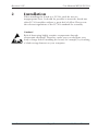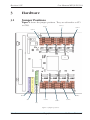
1
Meilhaus Electronic User Manual
ME-90 PC/104 2.2E
Embedded PC/104 RS232 and/or RS422/485
Interface Board with 8 Ports
Imprint
User Manual ME-90 PC/104
Revision 2.2E
Date: 2008-01-25
Meilhaus Electronic GmbH
Fischerstrasse 2
82178 Puchheim/Germany
www.meilhaus.com
© Copyright 2007 Meilhaus Electronic GmbH
All rights reserved. No part of this publication may be reproduced
or distributed in any form whether photocopied, printed, put
on microfilm or be stored in any electronic media without the
expressed written consent of Meilhaus Electronic GmbH..
Important note:
The information contained in this manual has been reviewed with
great care and is believed to be complete and accurate. Meilhaus
Electronic assumes no responsibility for its use, any infringements
of patents or other rights of third parties which may result from
use of this manual or the product. Meilhaus Electronic assumes no
responsibility for any problems or damage which may result from
errors or omissions. Specifications and instructions are subject to
change without notice.
All trademarks acknowledged.
Revision 2.1E
User Manual ME-90 PC/104
Contents
1 Introduction
1.1
1.2
1.3
1.4
5
Scope of Delivery
Features
System Requirements
Available Software
5
5
6
6
2 Installation
3 Hardware
7
9
3.1 Jumper Positions
3.2 Jumper Functions
9
10
3.2.1 Interrupts - UART and external
3.2.2 Base address
3.2.3 Termination, RTS/DTR and RS422/RS485 selection
10
11
12
Appendix
13
A
B
13
15
Specifications
Connector Pinouts
B1
B2
B3
B4
C
Technical Questions
C1
C2
C3
Contents
Position of pin field/connectors
Molex connector - interrupt (external)
Assignment of pin fields for the ports
Ribbon cables and sub-D connectors
Fax hotline
Customer service address
Updates
Page 3
15
15
15
17
18
18
18
18
Meilhaus Electronic
Revision 2.1E
1
User Manual ME-90 PC/104
Introduction
Dear customer,
Thank you for purchasing the ME-90 PC board! On purchase of
this board you have selected a high-quality technological product
that left our premises in perfect condition.
Please check that your delivery is complete and in good condition.
If any faults are obvious, please contact us immediately.
We recommend that you carefully read this manual before
installing the board - especially the installation chapter. This
also explains how the jumpers can be set for the various board
functions.
1.1
Scope of Delivery
It goes without saying that we make every effort to ensure that the
product package is complete. But to check whether your delivery
is complete, please check your package using the following list.
Your package should contain the following parts:
• RS232 or RS422/485 interface board, ME-90 PC/104 type, for the
ISA-based embedded-PC/104PCI form factor.
• Manual in pdf file format on the ME-Power CD (optional
printed version).
• 2x ribbon cables on each 4x 9-pin sub-D connector.
• Molex mating connector for interrupt (external).
1.2
Features
Model Overview
Model
Ports
Type
Rate1)
Bus
ME-90/8 RS232 PC/104
8
RS232
921.6 kBd PC/104
ME-90/8 RS485 PC/104
8
RS422 or RS485
921.6 kBd PC/104
selectable by jumper
ME-90/8 MIX PC/104
8
4x RS232, 4x RS422 921.6 kBd PC/104
or RS485 selectable
by jumper
Introduction
Page 5
Meilhaus Electronic
User Manual ME-90 PC/104
Revision 2.1E
The ME-90 embedded interface provides 8 ports on a board in
the ISA-based PC/104 form factor. These ports can be all RS232,
all RS422/RS485 or mixed (half-half). The transmission rate is
approx. 1 MBd max. (varies with system1)). With its extended
temperature range, ESD protection and an additional, external
interrupt input, the ME-90 is the ideal solution for points-of-sale,
retail and industrial data transfers.
• 8 ports, including ribbon cable on 8x 9-pin sub-D connectors.
• Transmission rates up to 1 MBd (varies with system1)).
• RS232 or RS422/RS485 or mixed ports (half-half).
RS422 or RS485 selectable by jumper
• RS422/RS485: Termination can be set with jumpers. RS485
transmission control with RTS or DTR half duplex or auto
switch.
• All RS232 handshake lines wired to the connectors. Additional
5V pin per port.
• Large address range (base address can be set with jumpers).
• Additional interrupt input/interrupt (external).
• Extended temperature range -40...+85°C.
• ESD protection (protection to withstand electrostatic discharge).
• For the ISA-based PC/104 form factor.
• Works as standard COM ports under Windows, Linux and
others. No special driver required.
1.3
System Requirements
The ME-90 will be used with a PC/104 stack with Intel® processor
or compatible.
1.4
Available Software
The ME-90 works as standard COM port under Windows, Linux,
and others. There is no need to install a special driver software.
1) Max. possible rate with the hardware. Actual rate depends on ISA bus
and system
Meilhaus Electronic
Page 6
Introduction
Revision 2.1E
2
User Manual ME-90 PC/104
Installation
When installing the board in a PC/104 stack do not use
inappropriate force. It should be possible to insert the board into
other PC/104 modules without a great deal of effort. Please note
the relevant regulations of the PC/104 standard for assembly.
Caution!
Risk of destroying highly sensitive components through
electrostatic discharge! Therefore, make sure you dissipate your
body‘s charge before installing the board, for example, by touching
a blank casing element on your computer.
Installation
Page 7
Meilhaus Electronic
Revision 2.1E
3
3.1
User Manual ME-90 PC/104
Hardware
Jumper Positions
Figure 1 shows the jumper positions. They are referred to as ST1
to ST69.
COM 3
COM 2
COM 4
COM 1
15
14
12
11
10
9
7
6
5
4
3
15
14
12
11
10
9
7
6
5
4
3
A11
A10
A09
A08
A07
A06
A05
A04
A03
ST2
COM 5
ST1
COM 8
COM 6
COM 7
ST3
Figure 1: Jumper positions:
Hardware
Page 9
Meilhaus Electronic
User Manual ME-90 PC/104
Revision 2.1E
3.2
Jumper Functions
3.2.1
Interrupts - UART and external
The UART interrupt is set with jumper ST1, and the external
interrupt with ST2 . IRQ 3 - 7, 9 - 12, 14, 15 (Figure 2a) can be set.
Factory setting: IRQ for external: 5. IRQ UART: 10. In the example
in Figure 2b the following are set: IRQ 9 for external, IRQ 10 for
the UART.
15
3
ST2
IRQ_external
15
3
ST1
IRQ_UART
Figure 2a: Jumper ST1 and ST2 for the interrupt settings
15
3
ST2
IRQ_exteral
15
3
ST1
IRQ_UART
Figure 2b: Example - Settings of IRQ 9 for external, IRQ 10 for the
UART
Meilhaus Electronic
Page 10
Hardware
Revision 2.1E
3.2.2
User Manual ME-90 PC/104
Base address
The board‘s base address is set with jumper ST3 (Figure 3a). The
jumpers are assigned to the address lines as shown in Figure 4.
„1“ means a set jumper. By default the address 608 hex is set. In
the example in Figure 3b 700 hex is set:
A11
A3
ST3
Base address
Figure 3a: ST3 jumper for the address setting
A11
A3
ST3
Base address
Figure 3b: Example - 700 hex address is set
A19 A18 A17 A16 A15 A14 A13 A12 A11 A10 A9
0
0
0
0
0
0
0
0
0
1
1
A8
A7
A6
A5
A4
A3
A2
A1
A0
1
0
0
0
0
0
0
0
0
=> 11100000000 => 700 Hex
Figure 4: Jumper assignment to the address lines
Hardware
Page 11
Meilhaus Electronic
User Manual ME-90 PC/104
3.2.3
Revision 2.1E
Termination, RTS/DTR and RS422/RS485 selection
These settings are made for the 8 ports individually with 8
jumper groups that are always arranged the same. The assignment
of the jumper groups to the ports is shown in Figure 1. Figure 5a
shows the functions of the jumpers. DTR/RTS is selected with
the triple jumper below. In the example in Figure 5b RTS is set.
The termination is set for In (above the triple jumper) and Out
using the three upper jumpers (pull-up, pull-down, differential,
none settings). No jumper is set in the example in Figure 5b and
therefore no termination. RS422 (open) or RS485 (inserted) is
selected directly with the jumpers above the triple jumper.
In, pull-up R
In, diff. R
In, pull-down R
open: RS422, set: RS485
Out, pull-up R
Out, diff. R
Out, pull-down R
open: RS422, set: RS485
DTR RTS
Figure 5a: Jumpers for setting the RS422/RS485 modes
In, pull-up R
In, diff. R
In, pull-down R
open: RS422, set: RS485
Out, pull-up R
Out, diff. R
Out, pull-down R
open: RS422, set: RS485
DTR RTS
Figure 5b: Example - RTS selected, no termination, RS422 mode
Meilhaus Electronic
Page 12
Hardware
Revision 2.1E
User Manual ME-90 PC/104
Appendix
A
Specifications
PC/104 interface
Bus interface
Base address
Interrupt
Data transfer
Ports
Interface type
Baud rate
Transmission
Appendix
ISA-16-bit based PC/104-embedded bus
Can be set with jumpers in a wide range;
the A3…A11 address lines are wired to
jumpers.
2 IRQs: IRQ of the UART and external
interrupt input, both individually selectable
by jumper 3…7, 9…12, 14, 15
ME-90/8 RS232 PC/104:
8x RS232
ME-90/8 RS485 PC/104:
8x RS422 or RS485 (selectable by jumper)
ME-90/8 MIX PC/104:
4x RS232 and 4x RS422 or RS485 (selectable
by jumper)
RS232 with handshake
RS422, RS485, termination (pull-up, pulldown (100 Ω), differential, none) is jumperselectable per port. RS485 transmission
control with RTS or DTR (jumper-selectable
per port) half duplex or auto switch.
75/110/134/150/300/600/1200/1800/2400/
4800/7200/9600/14,400/19,200/38,400/
57,600/115,200/128,000/230,400/460,800/
921,600 baud1)
Data bits: 4…8
Parity: None, Odd, Even, Mark, Space
Stop bits: 1, 1.5 or 2
Protocol: Xon/Xoff, Hardware, None
Page 13
Meilhaus Electronic
User Manual ME-90 PC/104
UART type, FIFO
Revision 2.1E
4x XR16L788 Quad UART or compatibles;
register-compatible with the 16550 with
integrated 64-byte transmit and receive
FIFOs per port
General Specifications
Current consumption Up to 1A max./typically 480mA
Dimensions
(mm) 90 x 96 (board only), 105 x 96 x 24
(board including connectors)
Connectors
PC/104 bus connector and 2x pin field
including 2x ribbon cables, each with 4x
9-pin D-sub connectors. Each port has an
additional 5V pin. 10-pole Molex connector
for interrupt (external) (Molex mating
connector included in delivery)
ESD protection
Up to 15kV (IEC 1000)
Temperature range
-40…+85°C
Humidity
20…55% (none condensing)
CE Certification
EC directive
Emission
Immunity
89/336/EMC
EN 55022
EN 50082-2
1) Max. possible rate with the hardware. Actual rate depends on ISA bus
and system.
Meilhaus Electronic
Page 14
Appendix
Revision 2.1E
User Manual ME-90 PC/104
B
Connector Pinouts
B1
Position of pin field/connectors
Interrupt (external) - Molex connector
Pin field for ports 1 - 4
PC/104 bus
Pin field for
ports 5 - 8
Figure 6: Position of pin fields/connectors on the ME-90
B2
Molex connector - interrupt (external)
1 2 3 4 5 6 7 8 9 10
1
2
IRQ In 1 3
IRQ In 2 4
GND
GND
5
6
reserved
reserved
7
8
GND
GND
9 n. c.
10 n. c.
Figure 7: Assignment of Molex connector (Molex mating connector
included in delivery)
B3
Assignment of pin fields for the ports
The two pin fields for ports 1 - 4 and 5 - 8 are assigned identically;
refer to Figure 7 and the table below:
39 37 35 33 31 29 27 25 23 21 19 17 15 13 11 9 7 5 3 1
board/print
40 38 36 34 32 30 28 26 24 22 20 18 16 14 12 10 8 6 4 2
Figure 8: 40-pole pin field of ME-90, front view
Appendix
Page 15
Meilhaus Electronic
User Manual ME-90 PC/104
Pin
1
2
3
4
5
6
7
8
9
10
11
12
13
14
15
16
17
18
19
20
21
22
23
24
25
26
27
28
29
30
31
32
33
34
35
36
37
38
39
40
Meilhaus Electronic
Port
1 or 5
1 or 5
1 or 5
1 or 5
1 or 5
1 or 5
1 or 5
1 or 5
1 or 5
1 or 5
2 or 6
2 or 6
2 or 6
2 or 6
2 or 6
2 or 6
2 or 6
2 or 6
2 or 6
2 or 6
3 or 7
3 or 7
3 or 7
3 or 7
3 or 7
3 or 7
3 or 7
3 or 7
3 or 7
3 or 7
4 or 8
4 or 8
4 or 8
4 or 8
4 or 8
4 or 8
4 or 8
4 or 8
4 or 8
4 or 8
Revision 2.1E
RS232
DCD
DSR
RxD
RTS
TxD
CTS
DTR
RI
SGND
5V
DCD
DSR
RxD
RTS
TxD
CTS
DTR
RI
SGND
5V
DCD
DSR
RxD
RTS
TxD
CTS
DTR
RI
SGND
5V
DCD
DSR
RxD
RTS
TxD
CTS
DTR
RI
SGND
5V
Direction
Input
Input
Input
Output
Output
Input
Output
Input
Signal GND
5 V pin
Input
Input
Input
Output
Output
Input
Output
Input
Signal GND
5 V pin
Input
Input
Input
Output
Output
Input
Output
Input
Signal GND
5 V pin
Input
Input
Input
Output
Output
Input
Output
Input
Signal GND
5 V pin
Page 16
RS422/485
RxD+
reserved
RxDreserved
TxD+
reserved
TxDreserved
SR
5V
RxD+
reserved
RxDreserved
TxD+
reserved
TxDreserved
SR
5V
RxD+
reserved
RxDreserved
TxD+
reserved
TxDreserved
SR
5V
RxD+
reserved
RxDreserved
TxD+
reserved
TxDreserved
SR
5V
Direction
Input
Input
Input
Output
Output
Input
Output
Output
Signal reference
5 V pin
Input
Input
Input
Output
Output
Input
Output
Output
Signal reference
5 V pin
Input
Input
Input
Output
Output
Input
Output
Output
Signal reference
5 V pin
Input
Input
Input
Output
Output
Input
Output
Output
Signal reference
5 V pin
Appendix
Revision 2.1E
B4
User Manual ME-90 PC/104
Ribbon cables and sub-D connectors
The ME-90 PC/104 package includes 2 ribbon cables on 4x 9-pole
D-sub connectors. These are assigned as shown below:
One 5 V pin per
port
B4.1
9-pole D-sub male connector for RS232 ports
TxD
RxD
DTR
DCD
GND
12 34 5
67 89
DSR
RTS
B4.2
RI
CTS
9-pole D-sub male connector for RS422/RS485 ports
TxD+
TxD-
RxDTxD+
RxDTxD-
RxD+
GND
12 34 5
Figures 9a - c: Ribbon
cable and 9-pole subD connector
Appendix
res.
67 89
res.
Page 17
res.
res.
Meilhaus Electronic
User Manual ME-90 PC/104
Revision 2.1E
C
Technical Questions
C1
Fax hotline
If you have technical questions or problems relating to the board, please
send a detailed description of the problem to our hotline:
Fax hotline:
within Germany:
from abroad:
(089) 89 01 66-28
++49 - 89 - 89 01 66-28
Email hotline:
[email protected]
C2
Customer service address
We hope that you will never need this part of the manual. If your
board has a technical defect, please contact us at:
Meilhaus Electronic GmbH
Abteilung Reparaturen
Fischerstrasse 2
D-82178 Puchheim, Germany
If you want to return your board for repair, please enclose
a detailed description of the error including details of your
computer/system and the software used! The simplest method is to
use our RMA procedure which you will find online at
www.meilhaus.com/en/service/rma-procedure/
C3
Updates
The current drivers for Meilhaus Electronic boards and our
manuals in PDF format are available from www.meilhaus.de
Meilhaus Electronic
Page 18
Appendix
Revision 2.1E
User Manual ME-90 PC/104
Index
A
I
address lines 11
assembly 7
auto switch 13
Installation 7
Interface 13
interrupt 5, 6, 10, 14, 15
IRQ 10, 13
B
Base address 6, 11, 13
Baud rate 13
J
jumper 9, 10, 11, 12, 13
Jumper functions 10
Jumper positions 9
C
COM port 6
connector 14, 15
Connector pinouts 15
CTS 16
Customer service address 18
L
Linux 6
M
ME-90/8 MIX PC/104 5, 13
ME-90/8 RS232 PC/104 5, 13
ME-90/8 RS485 PC/104 5, 13
Model Overview 5
Molex 5, 14, 15
D
D-sub 14, 17
Data bits 13
DCD 16
Dimension 14
driver software 6
DSR 16
DTR 6, 12, 13, 16
P
Parity 13
PC/104 5, 13, 14
PC/104 stack 6, 7
pin field 15
ports 12, 15, 17
Protocol 13
pull-down 12, 13
pull-up 12, 13
E
electrostatic discharge 7
Email hotline 18
ESD protection 6, 14
F
5 V Pin 16
Fax-Hotline 18
Features 5
FIFO 14
R
RI 16
ribbon cable 5, 14, 17
RMA procedure 18
RS232 5, 6, 13, 17
RS422 5, 6, 13, 17
RS422/RS485 selection 12
RS485 5, 6, 13, 17
RTS 6, 12, 13, 16
H
half duplex 13
handshake 6, 13
Hardware 9
Appendix
Page 19
Meilhaus Electronic
User Manual ME-90 PC/104
Revision 2.1E
RxD 16
S
Scope of delivery 5
Signal GND 16
Signal reference 16
Software 6
Specifications 13
standard COM port 6
Stop bits 13
System Requirements 6
T
Technical Questions 18
Temperature range 6, 14
Termination 12, 13
Transmission rates 6
TxD 16
U
UART 13
UART interrupt 10
Updates 18
W
Windows 6
X
Xon/Xoff 13
Meilhaus Electronic
Page 20
Appendix