1
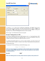
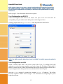
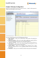
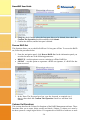
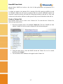
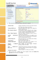
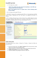
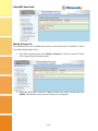
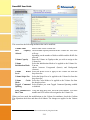
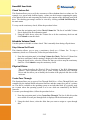
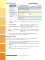
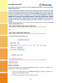
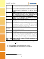
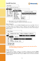
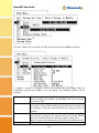
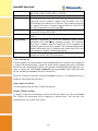
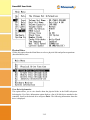
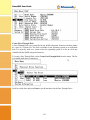
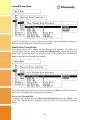
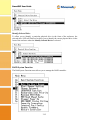
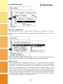
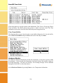
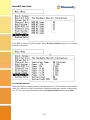
SmartGUI Configuration Guide Revision V1.40 February 2012 www.fibrenetix.com Limitations of Warranty and Liability Limitations of Warranty and Liability Fibrenetix has tested the hardware described in this User Guide and reviewed its contents. In no event will Fibrenetix, or its distributors, be liable for direct, indirect, incidental, or consequential damage resulting from any defect in the hardware or User Guide, even if they have been advised of the possibility of such damages. In particular, they shall have no liability for any program or data stored in or used with Fibrenetix products, including the costs of recovering or reproducing these programs or data. During the specified warranty period, Fibrenetix guarantees that the product will perform according to specifications determined by the manufacturer, and will be free of defects. Parts and labor of the received product, and replacement parts and labor are guaranteed during the specified warranty period. The warranty covers defects encountered in normal use of the product, and does not apply when damage occurs due to improper use, abuse, mishandling, accident, sand, dirt, excessive dust, water damage or unauthorized service. The product must be packed in its original packing material when shipped, or the warranty will be void. In all cases, proof of purchase must be presented when a warranty claim is being made. Fibrenetix operates a Return to Factory warranty. The period of this warranty is three (3) years. Warranty registration for your Fibrenetix system should be completed electronically via the web. Please register for the Return to Factory warranty at www.fibrenetix.com. Technical Support Policy If you have a problem installing your system or suspect it is malfunctioning, please contact Fibrenetix Support via email: [email protected], or register your support issue via our website: www.fibrenetix.com. Please have the model, serial number, date of purchase and the distributor/reseller’s name available, as you will need to provide this information to our support team. Return of Product If a distributor or Fibrenetix deems it necessary for a system to be returned for testing or servicing, a Return Materials Authorization (RMA) number will be issued. The RMA number must be placed on the outside of the carton in large, visible letters near the address label. Return the complete system including all cables and software. The system must be packed in the original packing materials and shipped prepaid. Fibrenetix will repair the system and return it prepaid by similar common carrier and priority. Please record the RMA number and make reference to it when enquiring on the status of the system. Contents Chapter 1 Introduction ...................................................................................................................................... 1-1 Product Applicability........................................................................................................... 1-1 Initial Setup.......................................................................................................................... 1-1 Browser Configuration via the serial port ....................................................................... 1-1 Browser Configuration via LAN ..................................................................................... 1-2 Text Configuration via RS-232 ....................................................................................... 1-3 Text Configuration via LAN ........................................................................................... 1-3 Chapter 2 Browser Configuration ..................................................................................................................... 2-1 Quick Functions ................................................................................................................... 2-2 RAID Set Functions ............................................................................................................. 2-2 Create a RAID Set ........................................................................................................... 2-3 Delete RAID Set .............................................................................................................. 2-3 Expand RAID Set ............................................................................................................ 2-4 Activate Incomplete RAID Set ........................................................................................ 2-4 Create Hot Spare .............................................................................................................. 2-5 Delete Hot Spare .............................................................................................................. 2-5 Rescue RAID Set ............................................................................................................. 2-6 Volume Set Functions .......................................................................................................... 2-6 Create a Volume Set ........................................................................................................ 2-7 Delete Volume Set ........................................................................................................... 2-9 Modify Volume Set ....................................................................................................... 2-10 Check Volume Set ......................................................................................................... 2-12 Stop Volume Set Check................................................................................................. 2-12 Physical Drives .................................................................................................................. 2-12 Create Pass Through ...................................................................................................... 2-12 Modify Pass Through .................................................................................................... 2-13 Delete Pass Through ...................................................................................................... 2-14 Identify Drive ................................................................................................................ 2-15 System Controls ................................................................................................................. 2-15 System Configuration .................................................................................................... 2-16 Fibre Channel Config .................................................................................................... 2-17 Ethernet Config.............................................................................................................. 2-18 Alert By Mail Configuration ......................................................................................... 2-19 SNMP Configuration ..................................................................................................... 2-20 NTP Configuration ........................................................................................................ 2-21 View Events/Mute Beeper ............................................................................................. 2-22 Generate Test Event....................................................................................................... 2-22 Clear Event Buffer ......................................................................................................... 2-23 Modify Password ........................................................................................................... 2-23 Upgrade Firmware ......................................................................................................... 2-24 Restart Controller .......................................................................................................... 2-25 Information ........................................................................................................................ 2-25 RAID Set Hierarchy ...................................................................................................... 2-25 System Information ....................................................................................................... 2-26 Hardware Monitor ......................................................................................................... 2-26 E8 GUI Screen ................................................................................................................... 2-27 Modifying and mapping E88 based volumes ................................................................ 2-27 Viewing the dual controller status ..................................................................................... 2-29 Chapter 3 Text Based Configuration ................................................................................................................ 3-1 Keyboard Navigation ....................................................................................................... 3-1 Login ................................................................................................................................ 3-1 Main Menu ....................................................................................................................... 3-1 Quick Volume/Raid Setup ........................................................................................... 3-1 RAID Level: ............................................................................................................ 3-1 Select Capacity: ....................................................................................................... 3-1 Stripe size ................................................................................................................ 3-1 Raid Set Function ......................................................................................................... 3-2 Create Raid Set ........................................................................................................ 3-2 Delete Raid Set ........................................................................................................ 3-3 Expand Raid Set ...................................................................................................... 3-3 Activate Incomplete Raid Set .................................................................................. 3-4 Create Hot Spare ...................................................................................................... 3-4 Delete Hot Spare ...................................................................................................... 3-5 Raid Set Information ............................................................................................... 3-5 Volume Set Function ................................................................................................... 3-6 Create Volume Set ................................................................................................... 3-6 Delete Volume Set ................................................................................................... 3-9 Modify Volume Set ................................................................................................. 3-9 Check Volume Set ................................................................................................. 3-11 Stop Volume Set Check......................................................................................... 3-11 Display Volume Set Info. ...................................................................................... 3-11 Physical Drive............................................................................................................ 3-12 View Drive Information ........................................................................................ 3-12 Create Pass-Through Disk ..................................................................................... 3-13 Modify Pass-Through Disk ................................................................................ 3-14 Delete Pass-Through Disk ..................................................................................... 3-14 Identify Selected Drive .......................................................................................... 3-15 RAID System Function .............................................................................................. 3-15 Mute The Alert Beeper........................................................................................ 3-16 Alert Beeper Setting .............................................................................................. 3-16 Change Password ................................................................................................... 3-17 RAID/JBOD Function .......................................................................................... 3-17 Background Task Priority...................................................................................... 3-18 Maximum SATA Mode ......................................................................................... 3-18 HDD Read Ahead Cache ....................................................................................... 3-19 Stagger Power On .................................................................................................. 3-19 HDD SMART Status Polling ................................................................................ 3-20 Capacity Truncation .............................................................................................. 3-20 Terminal Port Config. ......................................................................................... 3-21 Update Firmware ................................................................................................... 3-21 Restart Controller .................................................................................................. 3-22 U320 SCSI Target Config .......................................................................................... 3-23 Fibre Channel Config ................................................................................................ 3-23 Ethernet Configuration ............................................................................................... 3-24 DHCP Function ..................................................................................................... 3-24 Local IP address..................................................................................................... 3-25 Http Port Number .................................................................................................. 3-25 Telnet Port Number ............................................................................................... 3-25 Ethernet Address.................................................................................................... 3-25 View System Events .................................................................................................. 3-25 Clear Events Buffer.................................................................................................... 3-26 Hardware Monitor .................................................................................................... 3-26 System Information .................................................................................................... 3-27 SmartGUI User Guide Chapter 1 Introduction SmartGUI is a flexible intuitive configuration program for management of Fibrenetix RAID systems This User Guide is generic in nature as a range of Fibrenetix products use SmartGUI for configuration purposes. Even though the menus shown in this guide may not be an exact match for your particular Hardware System, it should be relatively straightforward to navigate the options with the help of this manual. Fibrenetix welcomes suggestions and feedback in relation to its products and guides. Product Applicability This guide is applicable to the Fibrenetix, FX, QX, VP and E series range of products. Initial Setup Systems may be configured from a browser based system through a series of hyper links or from a text menu. Both the browser menus and text menus can be accessed directly through either of two physical interfaces via an RJ-45 connection using TCP/IP protocol or through the serial port. The RJ-45 connection supports configuration via a browser or text configuration via telnet. The serial connection supports browser configuration using a proxy agent or text configuration via an RS-232 terminal emulation program. Only one configuration method should be in use at any one time – for example do not have a telnet session active and an http connection running at the same time. These connection methods are discussed in the following sections. Browser Configuration via the serial port The browser based RAID manager can be accessed via an http Proxy. The Fibrenetix RAID Systems comes with proxy software for Windows based host systems. To run the proxy software, double click on the executable file archttp.exe. The archttp dialog box appears. This allows a http session to be established via the serial port. Connect the supplied serial cable to an unused com port on the server and enter the corresponding com port number in the dialog shown in the diagram below. The Parameters for the General Setting are: • TCP Port value = 1 ~ 65535. • RAID Connected to value = 1 ~ 10 where 1 is for COM1, 2 for COM2 and so on... • BaudRate value = {2400, 4800, 9600, 19200, 38400, 57600, 115200} NOTE: The RAID controller default baud rate is 115200. When the program starts running, the following window appears: 1-1 SmartGUI User Guide To start the ArcHttp Proxy Server web-browser management, click Start. Type the User Name and Password when prompted. The RAID controller default User Name is "admin" and the Password is "0000". After entering user name and password, press Enter to start-up the Http Proxy Server. The RAID Management software is now accessible. Refer to page 2-1 for information on browser navigation. Browser Configuration via LAN The Firmware-embedded web browser RAID manager is an http–based application, which utilizes the browser installed on your operating system. You can use the Ethernet LAN port to configure the subsystem without any additional software or drivers. To configure the RAID subsystem on a local or remote machine, you need to know its IP Address. The default IP address is detailed on the Product Documentation and Quality Sheet provided with the unit. To launch the TCP/IP & Web Browser-based RAID manager, enter: http://[IP Address] NOTE: You must be logged-in as administrator with local admin rights on the workstation to remotely configure RAID subsystem. The user name and password are case sensitive. The default values are: User Name: Password: “admin” “0000” NOTE: The following menus are mainly taken from the E4 product, other products 1-2 will SmartGUI User Guide differ slightly (mainly in the area of channel configuration and quantity of devices but the options should be readily understood. products will differ slightly (mainly in the area of channel configuration and quantity of devices but the options should be readily understood. Refer to page 2-1 for information on browser navigation. Text Configuration via RS-232 Connect the supplied serial cable to an unused com port on the server and enter the corresponding com port number in the dialog shown in the diagram below. If using a program such as HyperTerminal enter the parameters shown below: NOTE: The RAID controller default baud rate is 115200. The default password supplied is “0000”. Text Configuration via LAN Attach a network cable from a hub to the system’s RJ-45 port. To configure the RAID subsystem on a local or remote machine, you need to know its IP Address. The default IP address is detailed on the Product Documentation and Quality Sheet provided with the unit or may be displayed on the front panel for the models that utilize the LCD panel. Start the telnet program by issuing the command telnet <IP address>. The default password supplied is “0000”. Refer to page 3-1 for information on configuring the system using the text menu. 1-3 SmartGUI User Guide Chapter 2 Browser Configuration When you log into SmartGUI for the first time (user name = “admin”, default password = “0000”) the overall display screen is shown: There are six main functions in the RAID Management software: • Quick Functions – allows you to quickly build a RAID system with minimal user input required. • RAID Set Functions – allows you to create, delete, modify and expand a RAID set as well as create and delete hot spare drives and rebuild RAID sets. • Volume Set Functions – allows you to create, delete, modify and check volume sets. • Physical Drives – allows you to create, modify and delete pass through drives as well as identify physical drive locations in the enclosure. • System Controls – allows you to configure system functions such as alarms, notifications and passwords, as well as upgrading controller firmware and restarting the controller. • Information – allows you to view RAID set, hardware and system wide information. 2-1 SmartGUI User Guide Quick Functions This function allows you to create a RAID Volume set with minimal input. When you click on the Quick Create link in the navigation panel the Quick Create screen is displayed in the information panel. This screen contains the following fields: The total number of disk drives that are available for the RAID Volume set. Select RAID Level Select the RAID level to be applied to the RAID Volume set from the drop-down list Maximum Capacity The maximum capacity in Gigabytes that is available Allowed for the creation of the RAID Volume set. Select Capacity Select the capacity that you wish to apply to the RAID Volume set. Volume Initialization Select whether you want the initialization of the Volume Mode Set to take place in the Foreground (fastest) or run in the Background (slow). Select Stripe Size Select the stripe size to apply to the RAID Volume Set from the drop-down list. Total Number of Disks To create a Volume Set using the Quick Create function, follow the procedure below: 1. 2. 3. Enter the information in the screen as described in the table above. Select the Confirm The Options check-box. Click Submit to create the RAID Volume Set. RAID Set Functions This section describes the RAID Set functions of the RAID Management software. These functions allow you to create, delete, modify and expand a RAID set as well as create and delete hot spare drives and rebuild RAID sets. 2-2 SmartGUI User Guide Create a RAID Set This function allows you to create a new RAID Set. To create a new RAID Set, follow the procedure below: 1. From the navigation panel, select Create RAID Set. In the information panel, the list of the disk drives available for inclusion in the RAID set is displayed. 2. Use the check boxes to select the drives to be included in the RAID Set and then check the Confirm The Operation check box and click Submit. 3. The RAID Set is created from the selected disk drives. Delete RAID Set This function allows you to delete a RAID Set. To delete a RAID Set, follow the procedure below: 1. From the navigation panel, select Delete RAID Set. In the information panel a list of available RAID Sets is shown. 2. Using the check box, select the RAID Set to be deleted and then check the Confirm 2-3 SmartGUI User Guide 3. The Operation check box and click Submit. 4. You will be asked to confirm the deletion. Expand RAID Set This function allows you to expand a RAID Set by adding one or more disk drives to it. This means that you do not have to delete an existing RAID Set and recreate it with more drives. To Expand a RAID Set, follow the procedure below: 1. From the navigation panel, select Expand RAID Set. In the information panel the list of previously created RAID Sets is displayed. 2. Using the check boxes, select the RAID Set to be expanded and then click Submit. 3. The list of disk drives that are available to be added to the RAID Set is displayed. 4. Using the check boxes, select the disk drive to be added to the RAID Set, then check the Confirm The Operation check box and click Submit to expand the RAID Set. Activate Incomplete RAID Set This function allows you to activate RAID Sets that are currently not active. When a drive is removed while the RAID subsystem is powered-off, the raid set state will change to Incomplete State. To continue to work when the RAID subsystem is powered on, you can use the Activate Raid Set option to activate the raid set. When this process is complete, the Raid State will change to Degraded Mode. Follow the procedure below to activate a RAID Set: 1. From the navigation panel, select Activate RAID Set. A list of the RAID Sets that can be activated is displayed in the information panel. 2. Using the check boxes, select the RAID Sets to be activated, and then click Submit, to make the RAID Sets active. 2-4 SmartGUI User Guide Create Hot Spare This function allows you to create a Hot Spare drive. The hot spare drive will always be ready to instantly be used in the event of a disk drive failing in a RAID Set. To create a Hot Spare drive, follow the procedure below: 1. From the navigation panel, select Create Hot Spare. The list of disk drives that are available to create a hot spare is shown in the information panel. 2. Using the check boxes, select the drive you wish to use to create the hot spare drive, then check the Confirm The Operation check box and then click Submit. 3. The Hot Spare drive is created. Delete Hot Spare This function allows you to delete a hot spare drive. Once the hot spare drive is deleted, the disk drive’s status is set to Free, and it can be used to create new RAID sets, expand existing RAID sets etc. To delete a hot spare drive, follow the procedure below: 1. From the navigation panel, select Delete Hot Spare. The list of hot spare drives is shown in the information panel. 2-5 SmartGUI User Guide 2. Using the check boxes, select the hot spare drive to be deleted, then check the Confirm The Operation check box and then click Submit. 3. Confirm the deletion, and the hot spare is deleted. Rescue RAID Set This function allows you to rebuild a RAID set if it has gone off-line. To rescue the RAID set, follow the procedure below: 1. From the navigation panel, click Rescue RAID Set. In the information panel you are asked to enter one of the following parameters: • RESCUE – use this option to recover a missing or off-line RAID Set. • SIGNAT – use this option to regenerate a RAID set signature, if a RAID Set has been recovered. 2. In the Enter The Keyword text box, type the keyword as required (see 1 above), then check the Confirm The Operation check box and then click Submit. Volume Set Functions This section describes the Volume Set functions of the RAID Management software. These functions allow you to create, delete, modify and check a Volume. A volume set is seen by the host system as a single logical device. It is organized in a RAID level with two or more 2-6 SmartGUI User Guide physical disks. RAID level refers to the level of data performance and protection of a volume set. A volume set capacity can consume all or a portion of the disk capacity available in a raid set. Multiple volume sets can exist on a group of disks in a raid set. Additional volume sets created in a specified raid set will reside on all the physical disks in the raid set. Thus, each volume set on the raid set will have its data spread evenly across all the disks in the raid set. Create a Volume Set This function allows you to create a new Volume Set. To create the new Volume Set, follow the procedure below: 1. From the navigation panel, select Create Volume Set. The list of RAID sets from which a Volume Set can be created is displayed in the information panel. 2. Using the check boxes, select the RAID Set that the Volume Set is to be created from then click Submit. 3. You must then set the attributes to be applied to the Volume Set. 2-7 SmartGUI User Guide 4. This screen has the following attributes that must be assigned: Displays the number of disks in the RAID set that the Volume Set is being created from. Select the RAID Level to apply to the Volume Set Volume RAID Level from the drop down list. The maximum capacity allowed for the Volume Max Capacity Allowed Set. This value will vary depending on the number of disks available and the RAID Set selected. Enter the Volume in Gigabytes that you wish to Select Volume Capacity assign to the Volume Set. Volume Initialization Select the Initialization Mode to be applied to the Volume Set. You can choose between Foreground Mode (fastest) and Background (slowest). Select the Stripe Size to be applied to the Volume Volume Stripe Size Set from the drop down list. Enter a name for the Volume Set Volume Name Select the Cache Mode to be applied to the Volume Cache Mode Volume Set from the drop down box. Tagged Command Select whether you want Tagged Command Queuing enabled or disabled. Queuing Member Disks Fibre Channel:LUN Using the drop down lists, select the FibreChannel, LUN base number and LUN offset to be assigned Base 1:Lun to the Volume Set. Enter the number of volumes to be created. Volumes to be created 5. When all the above attributes have been assigned, check the Confirm The Operation check box then click Submit. 1 LUN Base allows an offset to be used to avoid excessively long lists of IDs 2-8 SmartGUI User Guide 6. The Volume Set is created. NOTE: This operation may take some time depending on the RAID type selected and the size of the Volume Set. NOTE: If the capacity of the set is greater than 2 TB the following options become available: 1. “No” All Volumes will be under 2TB in size 2. “64Bit LBA” Volumes will be created Greater than 2TB in size. Operating System and HBA must be capable of addressing Over 2TB. This option is not supported in Fibrenetix U4 Systems. 3. 4K / For Windows This will create a Volume which will use a 4096Byte Block Size rather than using the standard 512Byte Block Size. It can allow a Volume Over 2TB in size to be accessible by an Operating System which cannot normally address over 2TB Delete Volume Set This function allows you to delete a Volume Set. To delete a Volume Set, follow the procedure below: 1. From the navigation panel, select Delete Volume Set. The list of previously created Volume Sets is shown in the information panel. 2. Using the check boxes, select the Volume Set that is to be deleted, then check the 3. Confirm The Operation check box and then click Submit. 4. Confirm the deletion when prompted to delete the Volume Set. 2-9 SmartGUI User Guide Modify Volume Set This function allows you to modify a previously created Volume Set. To modify a Volume Set, follow the procedure below: 1. From the navigation panel, select Modify Volume Set. The list of created Volume Sets is shown in the information panel. 2. Using the check boxes, select the Volume Set that you wish to modify then click Submit. The attributes for the selected Volume Set are displayed. 2-10 SmartGUI User Guide This screen has the following attributes that can be modified: Enter a name for the Volume Set Volume Name Max Capacity The maximum capacity allowed for the Volume Set. This value will vary Allowed depending on the number of disks available and the RAID Set selected. Enter the Volume in Gigabytes that you wish to assign to the Volume Capacity Volume Set. Select the Initialization Mode to be applied to the Volume Set. Volume Initialization Mode You can choose between Foreground (fastest) and Background (slowest). Volume RAID Select the RAID Level to apply to the Volume Set from the drop down list. Level Volume Stripe Size Select the Stripe Size to be applied to the Volume Set from the drop down list. Volume Cache Select the Cache Mode to be applied to the Volume Set from the drop down box Mode Tagged Command Select whether you want Tagged Command Queuing enabled or disabled. Queuing Fibre Channel:LUN Using the drop down lists, select the FibreChannel, LUN base number and LUN offset to be assigned to the Volume Set. Base 2:Lun When you have made the modifications to the Volume Set attributes, check the Confirm The Operation check box and then click Submit. The changes are applied to the Volume Set. 2 LUN Base allows an offset to be used to avoid excessively long lists of IDs 2-11 SmartGUI User Guide Check Volume Set This function allows you to verify the correctness of the redundant data in a volume set. For example, in a system with dedicated parity, volume set check means computing the parity of the data disk drives and comparing the results to the contents of the dedicated parity disk drive. The checking percentage can also be viewed by clicking on Raid Set Hierarchy in the main menu. To carry out the consistency check, follow the procedure below: 1. From the navigation panel, select Check Volume Set. The list of available Volume Sets is displayed in the information panel. 2. Using the check boxes, select the Volume Set to do the consistency check on and click Submit to start the check. Schedule Volume Check Use this option to schedule a volume check. This is normally done during off peak times. Stop Volume Set Check This function allows you to stop a consistency check on a Volume Set. To stop a consistency check on a Volume Set, follow the procedure below: 1. From the navigation panel, select Stop Volume Set Check. The list of Volume Sets that have consistency checks running is displayed in the information panel. 2. Using the check boxes, select the Volume Set that you wish to stop the consistency check for. Click Submit to stop the consistency check. Physical Drives This section describes the Physical Drives functions of the RAI Management software. These functions allow you to create, modify and delete Pass Through Drives and also allow you to identify the location of the physical disk drive in the enclosure. Create Pass Through This function allows you to create a Pass Through Disk Drive. A Pass Through Disk is not controlled by the internal RAID subsystem firmware and thus cannot be a part of a volume set. The disk is available to the operating system as an individual disk. It is typically used on a system where the operating system is to be on a disk not controlled by the RAID firmware. To create a pass through drive, follow the procedure below: 1. From the navigation panel, select Create Pass Through. The list of disk drives that are available to create pass through disks is displayed in the information panel. 2. Using the check boxes, select the disks that you want to assign as a pass through disk. 2-12 SmartGUI User Guide 3. Assign the attributes to the pass through drive by specifying the following information: Volume Cache Mode Tagged Command Queuing Fibre Base 3:Lun Select the Cache Mode to be applied to the Pass Through Drive using the drop down list. Select whether to enable or disable tagged command queuing using the drop down list. Channel:LUN Using the drop down lists, select the FibreChannel, LUN base number and LUN offset to be assigned to the Volume Set. 4. Once the attributes have been set, check the Confirm The Operation check box and then select Submit to create the Pass Through Disk. Modify Pass Through This function allows you to modify the attributes of an existing Pass Through Disk. To modify a Pass Through Disk, follow the procedure below: 1. From the navigation panel, select Modify Pass Through. The list of available Pass Through Disks is displayed in the navigation panel. 2. Using the check boxes, select the Pass Through Drive you wish to modify and click Submit. 3. The attributes for the selected Pass Through Drive are displayed in the information panel. 4. The following attributes can be modified on this screen: 3 LUN Base allows an offset to be used to avoid excessively long lists of IDs 2-13 SmartGUI User Guide Change the Cache Mode to be applied to the Pass Through Drive using the drop down list. Tagged Command Queuing Change whether to enable or disable tagged command queuing using the drop down list. Max SCSI Speed Change the maximum SCSI speed to be applied to the Pass Through Drive using the drop down list. Fibre Channel:LUN Using the drop down lists, select the FibreChannel, LUN base number and LUN offset to be assigned to the Base 4:Lun Volume Set. Volume Cache Mode 5. Once the changes have been made to the attributes of the Pass Through Drive, check the Confirm The Operation check box and then click Submit to make the changes to the Pass Through Drive. Delete Pass Through This function allows you to delete a Pass Through Drive. Once the Pass Through Drive has been deleted the disk status is set to Free and it is again available to be used in the creation of RAID Sets, Hot Spare Drives etc. To delete a Pass Through Drive, follow the procedure below: 1. From the navigation panel, select Delete Pass Through. The list of available Pass Through Drives is shown in the information panel. 2. 4 Using the check boxes, select the Pass Through Drive you wish to delete. Check the Confirm The Operation check box and then click Submit to delete the Pass LUN Base allows an offset to be used to avoid excessively long lists of IDs 2-14 SmartGUI User Guide Through Drive. Identify Enclosure This option may be used to identify a particular subsystem when multiple enclosures are used such as an E4 system configured with one or more JBOD units. Identify Drive This function allows you to see where a disk drive is physically located within the storage enclosure by making the drives LED flash on the front of the enclosure. To identify a drive, follow the procedure below: 1. From the navigation panel, select Identify Drive. The list of all available disk drives is shown in the information pane. 2. Using the check boxes, select the drive you wish to identify, and then click Submit. The LED for the disk drive will start to flash red on the front of the storage enclosure. 3. To stop the LED from flashing, click on any function in the navigation panel. System Controls This section describes the System Controls functions of the RAID Management Software. These functions allow you to configure alarms, notifications and passwords, as well as upgrading controller firmware and restarting the controller. 2-15 SmartGUI User Guide System Configuration This function allows you to set system wide parameters. To set the system parameters, follow this procedure: 1. From the navigation panel, select System Config. The system configuration attributes are displayed in the information panel. 2. The following system attributes can be set from this screen: System Beeper Setting Background Priority Task JBOD/RAID Configuration SATA NCQ Support HDD Read Ahead Cache Stagger Power On Control HDD SMART Status Polling Disk Capacity Truncation Mode Select whether you want the audible alarm beeper enabled or disabled using the drop down list. Set the priority level you wish to apply to tasks running in the background such as Initialization etc. using the drop down list. Set whether you want the system to run as a JBOD or a RAID system using the drop down list. Enable or Disable as appropriate. Sets the drives to read in more data than requested in anticipation of a subsequent request for the data This setting allows the drives to spin up in 0.5 second increments (from 1 second onwards). The current default setting is 0.4 seconds This function will poll the drives for SMART status Select how the disk capacity is to be truncated. For example, if you select Multiples of 10G, all disk capacities will be rounded down to the nearest 10G. 3. Once all the attributes have been set, check the Confirm The Operation check box and then click Submit to set the System Configuration parameters. 2-16 SmartGUI User Guide Fibre Channel Config 5 The E1-652-FC product features dual 4 gigabit Fibre Channel host interfaces. They can be configured from the Fibre Channel Config option. Use this screen to set up Fibre Channel negotiation speeds. Choices are 1,2,4 or auto. Default setting is Auto-Negotiate. Each channel can be configured independently. Fibre Channel topologies can be set up for Auto, Point to Point or Loop from this menu. Recommended settings are to hard set the speed to correspond to the HBA speed, set the topology to loop and distinct worldwide node names enabled. Each channel can also be set up for hard or soft addressing as appropriate for the user’s host environment. Distinct WWNN Option The Distinct WWNN option for each channel is used for Operating Systems/HBA configurations that require unique worldwide node names to distinguish between multiple channels. 5 Fibre Channel Product only 2-17 SmartGUI User Guide Note: Earlier systems may need to use the following procedure to make the Distinct WWNN option visible: From the Main Menu select the System Controls option then select Fibre Channel Config option. In the Channel 0 Hard Loop ID box type in the figure 911. Now move the cursor and click on another part of the screen. The Distinct WWNN option will now appear at the top of the Fibre Channel Config page. To enable a unique WWNN for each Fibre Channel Port at the rear of the Storage System, check the box beside the “Distinct WWNN for each Channel” option. Now check the Confirm the Operation box and then click on the Submit option. The parameter should now be updated. To ensure that the parameter has been successfully updated the RAID Controller should now be restarted. World wide name filtering can be set up for SAN environments by selecting the View/Edit Volume Set Host Filters link: Ethernet Config This function allows you to configure the Ethernet port for the enclosure. To configure the Ethernet port, follow the procedure below: 1. From the navigation panel, select Ethernet Config. The Ethernet parameters are displayed in the information panel. 2. The following parameters can be set from this screen: 2-18 SmartGUI User Guide DHCP Function Local IP Address Gateway IP Address Subnet Mask HTTP Port Number Telnet Port Number Current IP Address Current Gateway Address Current Subnet Mask Ethernet MAC Address Select whether you want to enable or disable DHCP functionality on the enclosure using the drop down list. Enter the local IP address in the boxes (if DHCP is disabled) Enter the Gateway IP address in the boxes Enter the Subnet Mask address in the boxes Enter the http Port Number in the box. Enter the Telnet Port Number in the box. Displays the current IP address. IP Displays the current Gateway IP address. Displays the current Subnet Mask. Displays the MAC address of the unit. 3. Once the parameters above have been set, check the Confirm The Operation check box and then click Submit. Alert By Mail Configuration This function allows you to configure the system to send an email to specified email addresses when an event occurs. To configure the Alert By Mail function, follow the procedure below: 1. From the navigation panel, select Alert By Mail Config. The email alert parameters are displayed in the information panel. 2. The following parameters can be set from this screen: SMTP Server Address Sender Name Mail Address IP Enter the IP address of the SMTP server to be used for email notifications. Enter a name that will be displayed to the person receiving the email alert. Enter the email address that will appear as the Mail From 2-19 SmartGUI User Guide address for the email alert. Account Enter the account name (user name) for the email notification account on the email server. Password Enter the password for the email notification account on the email server. MailTo Name 1 to 4 Enter up to 4 names that email event notifications will be sent to. Mail Address Enter the email address of the person named in the Mail To Name X box. Event Notification Select the level of events that will be notified to the specified Configuration email addresses. Notification For No Check this check box if you want a notification sent when no Events events occur in a 24 hour period (could indicate that the system has stopped for some reason). 3. Once all the parameters have been set, check the Confirm The Operation check box and then click Submit to configure email notification. 4. SNMP Configuration This function allows you to configure SNMP settings for the RAID Controller. To configure the SNMP settings, follow the procedure below: 1. From the navigation panel, select SNMP Configuration. The SNMP attributes will be displayed in the information panel. 2. This screen contains the following fields: 2-20 SmartGUI User Guide Enter the IP Address and Port Number of the SNMP traps. SNMP System Configurations Enter the SNMP System parameters here. Enter a Community, Contact, Name and Location Select the level of events for which you wish SNMP Trap Notification SNMP traps sent using the check boxes. Configurations SNMP Trap Configurations Once the above information has been added, check the Confirm The Operation check box and then click Submit to set the SNMP Configuration parameters. NTP Configuration Use this screen to input the parameters of the Network Time Protocol (NTP) server to use for time synchronization. 2-21 SmartGUI User Guide View Events/Mute Beeper This function allows you to view events generated by the RAID controller. Viewing events will also mute the alarm beeper. To view events, select View Events/Mute Beeper from the navigation panel. The event log is opened and you can view all the generated events. This screen shows the date and time that the events took place, the device that the event was generated from and the type of the event etc. Generate Test Event This function allows you to generate a test event. This is used to ensure that your event notification process is working correctly. Select Generate Test Event from the navigation panel to bring up the Generate Test Event screen. Generate the test event by checking the Confirm The Operation check box and then click Submit. 2-22 SmartGUI User Guide Clear Event Buffer This function allows you to clear the event buffer. Select Clear Event Buffer from the navigation panel to bring up the Clear Event Buffer screen. To clear the event buffer, check the Confirm The Operation check box and then click Submit. Modify Password This function allows you to change the password 6 used to log into the RAID Controller. To modify the password, follow the procedure below: 1. From the navigation panel, select Modify Password. The Modify Password screen is displayed in the information panel. 6 If the password is changed from the default ensure that a note is keep in a safe secure place. Do not lose this password. 2-23 SmartGUI User Guide 2. Enter the original password and then enter the new password twice. 3. Check the Confirm The Operation check box and then click Submit. Upgrade Firmware This function allows you to upgrade the firmware on the RAID controller. To upgrade the firmware, follow the procedure below: 1. From the navigation panel, select Upgrade Firmware 7. The upgrade firmware screen is displayed in the information panel. 2. Enter the path and filename of the latest firmware image or click Browse and search for the file. 3. Check the Confirm The Operation check box and then click Submit to start the firmware upgrade. 7 The firmware consists of three files and should be loaded in the following filename extension order – MBR0, Boot, Firm. 2-24 SmartGUI User Guide Restart Controller This function allows you to restart the controller. To restart the controller, select Restart Controller from the navigation panel and the restart controller screen is displayed in the information panel. To restart the controller, check the Confirm The Operation check box and then click Submit. Information These functions allow you to view general information relating to the RAID sets, system and hardware. RAID Set Hierarchy This function allows you to view general information relating to the RAID sets created on the system. To view the RAID set hierarchy, select RaidSet Hierarchy from the navigation panel. Details about the RAID sets created on the system are displayed in the information panel. This screen shows the list of RAID Sets created on the system along with details relating to these RAID sets, such as the disk drives used in the RAID set, Volume sets created from the RAID sets, the status of the Volume sets and the capacity of each RAID set. 2-25 SmartGUI User Guide At the bottom of the screen is a list of all the disk drives on the system showing what each disk is used for, its capacity and the model of the disk drive. NOTE: For more detailed information on a RAID Set, Volume Set or Disk Drive, click on its hyperlinked name. System Information This function displays detailed information about the RAID Controller. To view the detailed information, select System Information from the navigation panel. The system information is displayed in the information panel. Hardware Monitor This function allows you to view hardware information relating to the storage enclosure. To view the hardware information, select Hardware Monitor from the navigation panel. The hardware information is displayed in the information panel. 2-26 SmartGUI User Guide E8 GUI Screen The E8 system is similar, however there are a number of screen that differ. The opening menu is shown below: Modifying and mapping E88 based volumes One of the areas that differs with the E8 is the fact that dual controllers are used as opposed to single controller configurations. For redundancy volumes can be mapped to similar ports on each controller. Fibre Channel ports and setting can be modified from the <System Controls> screen. The following screenshot is taken from the path <System Controls> <Fibre Channel Config> and allows various settings to be changed. 2-27 SmartGUI User Guide The next screen shows (in dual controller mode) how the volume is mapped to corresponding ports across both controllers. For performance reasons different volumes can be spread across ports in a breadth first configuration ( volume 1 port 1, volume 2 port 2, …). The port mapping is done during volume creation or by modifying the volume. To do this select <Volume Set Functions> <Modify Volume Set>. Select the volume to be modified and then select <Submit>. On the next screen select corresponding ports and then check the <Confirm The Operation> box and select, Submit>. 2-28 SmartGUI User Guide Viewing the dual controller status Select <Information> <System Information> to view information relating to dual controller operation. 2-29 SmartGUI User Guide Chapter 3 Text Based Configuration This chapter describes how to configure the RAID Controller from the serial port using a VT100 terminal emulation program or through the Ethernet connector using telnet. For details on how to access the VT100 menus, refer to Chapter 1. Keyboard Navigation The following key–functions are used to navigate through the VT-100 RAID configuration utility. Key Function Arrow Key Enter Key ESC Key L Key X Key Move cursor Submit selection function Return to previous screen Line draw Re-draw Login Before accessing the main menu, you are required to enter a password. The default password is 0000. Once you are logged in you can change the password via the Change Password option under the RAID Set Function menu item. Main Menu The main menu provides access to all the available functions. Refer to the SmartGUI manual for a view of the complete menu structure. Use the arrow keys to move up and down through the menu, and then press Enter to select a menu item or Esc to go back to the previous menu. Quick Volume/Raid Setup Raid Set Functions Volume Set Functions Physical Drive Functions Raid System Function U320 SCSI Target Config Ethernet Configuration View System Events Clear Event Buffer Hardware Monitor System Information Create a default configuration based on the number of physical disks installed Create a customized raid set Create a customized volume set View individual disk information Set the raid system configurations Enable or Disable U320 SCSI Targets Configure the Ethernet port for the RAID enclosure. View all system events in the system Clear all system event information View all system hardware information View the controller system information 3-1 SmartGUI User Guide Quick Volume/Raid Setup Quick Volume/Raid Set-up is the fastest way to prepare a raid set and volume set. It can be completed with just a few keystrokes. Although drives of different capacity may be used in the raid set, the smallest capacity drive in the RAID set is used as the capacity of all disk drives in the RAID set. RAID Level: The total number of physical drives in a specific RAID set determines the RAID levels that can be implemented. Press Enter on Quick Volume/Raid Set-up from the main menu; all possible RAID levels will be displayed, as shown below: Select Capacity: A single volume set is created that consumes all or a portion of the disk capacity available in the RAID set. To define the capacity of the volume set, use the Available Capacity screen. The default value for the volume set is displayed. Use the arrow keys to modify the volume set capacity and press Enter to accept the value. If it only uses part of the raid set capacity, you can use the Create Volume Set option to define additional volume sets. Stripe size This parameter sets the size of the stripe written to each disk in a RAID 0, 1, 0+1, 5, or 6 logical drive. You can set the stripe size to 4 KB, 8 KB, 16 KB, 32 KB, 64 KB, or 128 KB. A larger stripe size provides better read performance, especially if your computer processes mostly sequential reads. However, if your computer processes a lot of random read requests, a small stripe size should be selected. 3-1 SmartGUI User Guide Press Yes in the Create Vol/Raid Set dialog box, the raid set and volume set will start to initialize. Raid Set Function RAID Sets can be configured manually from the RAID Set Function menu. From this function you can manually create, delete, expand and activate a raid set. Create Raid Set To create a RAID Set, follow the procedure below: 1. Select Raid Set Function from the main menu. 2. Select Create Raid Set from the Raid Set Function menu. 3. The Select Drive For Raid Set window is displayed listing the available drives. Use the arrow keys to select specific physical drives. 4. Press Enter to select the drives for inclusion 8 in the RAID Set. Repeat this step, for all drives you want to include in the RAID set. 5. When you have finished selecting the drives to be included in the Raid Set, press Esc. Press Yes to confirm the creation. 8 Selected drives are shown by an asterix (*) 3-2 SmartGUI User Guide 6. The Edit The Raid Set Name option appears. Enter a name for the RAID Set by entering 1 to 15 alphanumeric characters. The default raid set name is Raid Set #. Delete Raid Set To delete a RAID set, select the raid set number you want to delete from the Select Raid Set to Delete option. The Delete Raid Set screen appears, select Yes to delete it. A second confirmation screen appears. Select Yes again to reconfirm the deletion. CAUTION: Deleting a Raid Set is a destructive action that will cause the loss of all data existing on the Raid Set. Expand Raid Set Instead of deleting a raid set and recreating it with additional disk drives, the Expand Raid Set function allows you to add drives to an existing raid set. 3-3 SmartGUI User Guide To expand a raid set, follow the procedure below: 1. Click Expand Raid Set. If there are available disks, the Select Drives For Raid Set Expansion menu appears. 2. Select the Raid Set and then select the disk. 3. A confirmation screen appears. Select Yes to confirm. The new raid set capacity can be defined as one or more volume sets. Follow the instructions in the Volume Set Function to create volume sets. NOTE: Once the Expand Raid Set process has started, you cannot stop it. The process must be completed. NOTE: If a disk drive fails during raid set expansion and a hot spare is available, an auto-rebuild operation will occur upon completion of the raid set expansion. Activate Incomplete Raid Set When a drive is removed while the RAID subsystem is powered-off, the raid set state will change to Incomplete State. To continue to work when the RAID subsystem is powered on, you can use the Activate Raid Set option to activate the raid set. When this process is complete, the Raid State will change to Degraded Mode. Create Hot Spare Selecting the Create Hot Spare option from the Raid Set Function menu, brings up a list of all physical disks which are available: 3-4 SmartGUI User Guide 1. Scroll to the required disk using the arrow keys. 2. Press Enter to select a disk. 3. Select Yes in “Create Hot Spare?” to designate the drive as a hot spare. Delete Hot Spare This option allows you to delete a hot spare drive. 1. Scroll to the hot spare drive to be deleted using the arrow keys. 2. Press Enter to select the drive 3. Select Yes in “Delete Hot Spare?” to delete the hot spare. Raid Set Information To display Raid Set information, scroll to the desired Raid Set number and press Enter. The Raid Set Information is displayed. The following information is shown for the RAID set: 3-5 SmartGUI User Guide Shows the name of the Raid Set Shows the number of disks belonging to the Raid Set. Shows the status of the Raid Set. Shows the total capacity available in the Raid Set. Shows the non-allocated capacity that can be used to define more Volume Sets. Min Member Shows the capacity of the smallest disk drive in the Raid Set. Disk Size Member Disk Shows the disks that belong to the Raid Set by naming the channel/slot they are attached to. Channel Raid Set Name Member Disks RAID State Total Capacity Free Capacity Volume Set Function A Volume Set is seen by the host system as a single logical drive. It is organized in a RAID level with two or more physical drives. RAID level refers to the level of data performance and protection of a Volume Set. A Volume Set capacity can consume all or a portion of the drive capacity available in a Raid Set. Multiple Volume Sets can exist on a group of drives in a Raid Set. Additional Volume Sets created in a specified Raid Set will reside on all the physical drives in the Raid Set. Therefore, each Volume Set on the Raid Set will have its data spread evenly across all drives in the Raid Set. The volume set features are as follows: • Volume sets of different RAID levels may co-exist on the same raid set. • Up to 16 volume sets in total can be created. Create Volume Set To create a volume set, follow the procedure below: 1. Select Volume Set Function from the Main menu. 2. Choose Create Volume Set from Volume Set Function menu. 3-6 SmartGUI User Guide 3. The Create Volume From Raid Set option appears. This screen displays the available raid sets. Scroll to the required raid set and press Enter. 4. The Volume Creation option is displayed showing the current settings for the volume set. The Volume Creation option allows you to select the Volume Name, RAID level, Capacity, Stripe Size, SCSI or FC ID/LUN, Cache Mode, Tag Queuing and Max Sync Rate. You can modify the default values in this menu by scrolling to the required option and pressing Enter. Press Esc to save the value and return to the menu. The following table shows the attributes that can be modified: 3-7 SmartGUI User Guide Volume Name The default volume name will always appear as Volume Set. #. You can rename the volume set providing it does not exceed the 15character limit. To set the RAID level for a Volume Set, highlight Raid Level and RAID Level press Enter. The available RAID levels for the current Volume Set are displayed. Select the required RAID level and press Enter to confirm. The maximum size of the volume is always the default setting. You Capacity can increase or decrease the capacity using the UP and DOWN arrow keys. Each volume set can have a capacity which is less than, or equal to, the total capacity of the raid set on which it resides. This parameter sets the size of the segment written to each disk in a Stripe Size RAID 0, 1, 0+1, 5 or 6 logical drive. You can set the stripe size to 4 KB, 8 KB, 16 KB, 32 KB, 64 KB, or 128 KB. SCSI Channel Your system has an Ultra 320 SCSI channel 9. The Select SCSI Channel option appears. Select the channel number and press Enter to confirm. Each SCSI device attached to the SCSI card, as well as the HBA SCSI ID card itself, must be assigned a unique SCSI ID number. An LVD SCSI channel can connect up to 15 devices. The Volume Set will appear as a large SCSI device. You must assign an ID from a list of SCSI IDs. ID 7 is normally reserved for the HBA. Each SCSI ID can support up to 8 LUN’s. Most SCSI host adapters SCSI LUN treat each LUN like a SCSI disk. You can set the cache mode to: Write-Through Cache or WriteCache Mode Back Cache. Enabling Tag-Queuing is useful for enhancing overall system Tag Queuing performance under multi-tasking operating systems. The Command Tag (Drive Channel) function controls the SCSI command tag queuing support for each drive channel. This function should remain enabled and should only be disabled when using older SCSI host cards that do not support command tag queuing. Max Sync The RAID subsystem 320 MB/sec as the highest data transfer rate for the Ultra 320 system. Rate 5. When the volume set parameters are modified, press Esc to confirm. A Fast Initialization option will be displayed. • • 9 Select Foreground to start Fast Initialization of the volume set. Select Background to start Normal Initialization of the volume set. SCSI model – FC model has dual 4 Gigabit FC links 3-8 SmartGUI User Guide 6. Repeat steps 3 to 5 to create additional volume sets. 7. The initialization progress is displayed at the bottom of the screen. Delete Volume Set To delete a Volume set, select the Delete Volume Set option by pressing Enter. The list of all available RAID sets is displayed. Scroll to a RAID Set, then press Enter to show all Volume Sets in the raid set. Select the Volume Set number you wish to delete and press Enter to delete it. CAUTION: Deleting a Volume Set is a destructive action that will cause the loss of data existing in the Volume Set. Modify Volume Set Use this option to modify a volume set. To modify a Volume Set, select the Modify Volume Set option, and then press Enter. The list of all available RAID sets is displayed. Scroll to the required Raid Set number and, press Enter to show all Volume Set associated with the RAID set. 3-9 SmartGUI User Guide Select the Volume Set you which to modify from the list and press Enter to modify it. To change a Volume set attribute, scroll to the attribute and press Enter. Make the modification and then press ESC to save the change. The following attributes can be modified: Name The default volume name will always appear as Volume Set. #. You can rename the volume set providing it does not exceed the 15-character limit. To set the RAID level for a Volume Set, highlight Raid Level and RAID Level press Enter. The available RAID levels for the current Volume Set are displayed. Select the required RAID level and press Enter to confirm. The maximum size of the volume is always the default setting. You Capacity can increase or decrease the capacity using the UP and DOWN arrow keys. Each volume set can have a capacity which is less than, or equal to, the total capacity of the raid set on which it resides. This parameter sets the size of the segment written to each disk in a Stripe Size Volume 3-10 SmartGUI User Guide SCSI Channel SCSI ID SCSI LUN Cache Mode Tag Queuing Max Sync Rate RAID 0, 1, 0+1, 5 or 6 logical drives. You can set the stripe size to 4 KB, 8 KB, 16 KB, 32 KB, 64 KB, or 128 KB. Select the SCSI channel number and press Enter to confirm. Each SCSI device attached to the SCSI card, as well as the HBA card itself, must be assigned a unique SCSI ID number. An LVD SCSI channel can connect up to 15 devices. The Volume Set appears as a large SCSI device. You must assign an ID from a list of SCSI IDs. ID 7 is normally reserved for the HBA. Each SCSI ID can support up to 8 LUN’s. Most SCSI host adapters treat each LUN like a SCSI disk. You can set the cache mode to: Write-Through Cache or Write-Back Cache. Enabling Tag-Queuing is useful for enhancing overall system performance for multi-tasking operating systems. The Command Tag (Drive Channel) function controls the SCSI command tag queuing support for each drive channel. This function should remain enabled and should only be disabled when using older SCSI host cards that do not support command tag queuing. The RAID subsystem supports 320 MB/sec as the highest data transfer rate for the Ultra 320 SCSI system. Check Volume Set Use this option to verify the integrity of the redundant data in a volume set. For example, in a system with dedicated parity, volume set check means computing the parity of the data disk drives and comparing the results to the contents of the dedicated parity disk drive. To check a Volume Set, select Check Volume Set, then press Enter. Select a Raid Set from the list, and then press Enter to show all Volume Sets. Select the Volume Set from the list and press Enter to select it. A confirmation screen is displayed. Press Yes to start the check. Stop Volume Set Check Use this option to stop all Check Volume Set requests. Display Volume Set Info. To display Volume Set information, scroll to the desired Volume Set, then press Enter. The Volume Set Information will be displayed as shown below. You can only view information for one Volume Set at a time. 3-11 SmartGUI User Guide Physical Drive Choose this option from the Main Menu to select a physical disk and perform operations (described below) on it. View Drive Information This option allows you to view details about the physical disks in the RAID subsystem. Selecting the View Drive Information option displays a list of all disk drives attached to the controller. Scroll to the desired drive and press Enter. The following information about the drive is displayed: 3-12 SmartGUI User Guide Create Pass-Through Disk A Pass-Through Disk is not controlled by the RAID subsystem firmware and thus cannot be a part of a Volume Set. The disk is available to the operating system as an individual disk. It is typically used on a system where the operating system is to be on a disk not controlled by the RAID subsystem firmware. To create a Pass Through Disk, select Create Pass Through Disk from the menu. The list of available disk drives is displayed. Scroll to a disk drive and press Enter to set the attributes for the Pass Through Drive. 3-13 SmartGUI User Guide Scroll to the attribute you wish to edit and press Enter. Edit the attribute and then press ESC to save the change and return to the previous menu. Modify Pass-Through Disk This option allows you to modify the Pass-Through Disk Attributes. To modify PassThrough Disk attributes, select the Modify Pass-Through Drive option and then press Enter. All Pass-Through Drives are displayed. Scroll to the required drive and then press Enter to show the Pass-Through Disk Attributes. Select the parameter from the list you which to change, press Enter to modify it, then press ESC to save the change and return to the previous menu. Delete Pass-Through Disk To delete a Pass-through drive select Delete Pass-Through Drive, then press Enter. A list of all Pass Through Drives is displayed. Select the drive you wish to delete and press Enter. 3-14 SmartGUI User Guide Identify Selected Drive To allow you to identify a particular physical drive in the front of the enclosure, the selected drive LED will flash red to allow you to identify the correct physical drive in the front of the enclosure when the Identify Selected Device is selected. RAID System Function The Raid System Function menu allows you to manage the RAID controller. 3-15 SmartGUI User Guide Mute The Alert Beeper The Mute The Alert Beeper function allows you to control the RAID subsystem Beeper. Select Yes and press Enter in the dialog box to mute the beeper. The beeper will still activate on the next event. Alert Beeper Setting The Alert Beeper function allows you to Disable or Enable the RAID subsystem controller beeper. Select Disabled and press Enter to turn the beeper off. Or, select Enable and press Enter to turn the beeper on. 3-16 SmartGUI User Guide Change Password The password option allows you to set or clear the raid subsystem’s password protection feature. Once the password has been set, you can only monitor and configure the raid subsystem by providing the correct password. The password is used to protect the RAID subsystem from unauthorized entry. The controller will check the password only when entering the Main menu from the initial screen. The RAID subsystem will automatically go back to the initial screen when it does not receive any command for twenty seconds. To disable the password, press Enter (without entering any alphanumeric characters) in both the Enter New Password and the Re-Enter New Password column. The existing password will be cleared. No password checking will occur when entering the main menu from the starting screen. RAID/JBOD Function The RAID/JBOD Function allows you to instruct the system as to how it should handle the drives. RAID will give you the functionality of creating RAID sets and JBOD will treat all drives as individual drives with no Raid protection. 3-17 SmartGUI User Guide Background Task Priority The Background Task Priority function allows you to specify how tasks that run in the background are prioritized. Select the amount of resources (in percent) to be allocated to background tasks. Maximum SATA Mode The Maximum SATA Mode function allows you to set the maximum SATA mode that the system can support as well as enabling Native Command Queuing (NCQ). Select the Max SATA mode from the list and press Enter to select. 3-18 SmartGUI User Guide HDD Read Ahead Cache Select the read ahead function to enable pre-fetching of data that has not specifically been requested in anticipation of subsequent reads for this data. This function may improve sequential read throughput. Stagger Power On This function is used to prevent current surge when powering up all disks simultaneously. The interval selected is the interval between the power up command issued to each drive in turn. For example a two second interval ensures that commands are issued to individual drives every two seconds. 3-19 SmartGUI User Guide The setting should be set to a minimum of 2.5 seconds. HDD SMART Status Polling This features allows the controller to take advantage of monitoring SMART information from the disk drives. Capacity Truncation The Capacity Truncation function allows you to select how the disk capacity is to be truncated. For example, if you select Multiples of 10G, all disk capacities will be rounded down to the nearest 10GB i.e. if a disk has capacity of 412GB then it will appear as having a capacity of 410GB on the system. Select the Capacity Truncation setting from the list and 3-20 SmartGUI User Guide press Enter to select it. This may be useful if mixing drive vendors with similar capacities (or newer revision models of similar capacity form the same vendor). Terminal Port Config. The Terminal Port Config function allows you to configure the terminal port. From this screen you can set the Baud Rate and the Stop Bits values. Press Enter to select Baud Rate or Stop Bit and edit the settings. Press ESC to save the change and return to the previous menu. Update Firmware NOTE: You can update the firmware through the VT100 terminal via the controller’s serial port. 3-21 SmartGUI User Guide NOTE: You can update the firmware via the firmware-embedded web browserbased RAID manager through the controller’s 10/100 Ethernet LAN port. Restart Controller This function allows you to restart the controller. Select Restart Controller from the menu and press Enter. The Restart Controller confirmation screen appears. Select Yes to restart the RAID controller. NOTE: Ensure that there is no Host and Drive activity before restarting the controller. 3-22 SmartGUI User Guide U320 SCSI Target Config 10 This function allows you to configure U320 SCSI targets. Select U320 SCSI Target Config from the Main Menu and press Enter. The list of available U320 SCSI targets is displayed. Scroll to the required SCSI target and press Enter. Select Disable to disable the SCSI target, or select Enable to enable the SCSI target. Fibre Channel Config 11 The corresponding screen for the Fibre Channel system is shown below: Each channel can be configured independently. Default speed is Auto Negotiate. The next screen shows how to change the topology for each channel. Available options are Auto, Loop or Point-to-Point. 10 11 SCSI unit only Fibre Channel unit only 3-23 SmartGUI User Guide Ethernet Configuration These functions allow you to set the controller Ethernet port configuration. You do not need to create a reserved space on the arrays before the Ethernet port and http service will function. Scroll to a parameter in the list and press Enter to open it for editing. Make the necessary changes and then press ESC to save the changes and return to the previous menu. DHCP Function DHCP (Dynamic Host Configuration Protocol) is a protocol that lets network administrators manage centrally and automate the assignment of IP (Internet Protocol) configurations on a computer network. When using the Internet's set of protocols (TCP/IP), in order for a computer system to communicate to another computer system it needs a unique IP address. Without DHCP, the IP address must be entered manually at each computer system. DHCP lets a network administrator supervise and distribute IP addresses from a central point. The purpose of DHCP is to provide the automatic (dynamic) allocation of IP client configurations for a specific time period (called a lease period) and to eliminate the work necessary to administer a large IP network. 3-24 SmartGUI User Guide To manually configure the IP address of the controller, scroll to the Ethernet Configuration Function and press Enter. The Ethernet Configuration menu appears on the screen. Scroll to the DHCP Function, then press Enter to show the DHCP setting. Select the Disabled or Enabled option to enable or disable the DHCP function. Local IP address If you intend to set up your client computers manually, make sure that the assigned IP address is in the same range as your default router address and that it is unique to your private network. However, we would highly recommend that if you have a network of computers and the option to assign your TCP/IP client configurations automatically, please do so. An IP address allocation scheme will reduce the time it takes to set-up client computers and eliminate the possibilities of administrative errors. To manually configure the IP address of the controller, scroll to Local IP Address and press Enter to show the default address setting. You can now reassign the IP address of the controller. Press ECS when finished to save the IP address and return to the previous menu. Http Port Number This function allows you to set the port number to be used as the http port for the RAID controller. Select http Port Number and press Enter. Type a new port number and then press ESC to save the new Port Number and return to the previous menu. Telnet Port Number This function allows you to set the port number to be used as the Telnet Port for the RAID controller. Select Telnet Port Number and press Enter. Type a new port number and then press ESC to save the new Port Number and return to the previous menu. Ethernet Address A MAC address stands for Media Access Control address and is your computer's unique hardware number. On an Ethernet LAN, it's the same as your Ethernet address. When you are connected to the Internet from the RAID controller Ethernet port, a correspondence table relates your IP address to the RAID controller’s physical (MAC) address on the LAN. View System Events This function allows you to view the RAID controller system events information. To view the events, select View System Events, then press Enter. The RAID subsystem events screen appears. 3-25 SmartGUI User Guide Choose this option to view the system events information: Time, Device, Event type, Elapse Time and Errors. The RAID system does not have a built in real time clock. The Time information is the relative time from the RAID subsystem being powered on. Clear Events Buffer This function allows you to clear the entire events buffer information. To clear the buffer, select Clear Events Buffer and press Enter, then select Yes and press Enter. Hardware Monitor The Hardware Monitor Information provides the temperature, of any drives present within the enclosure. It also provides the temperature, fan speed (chassis fan) and the voltage of the RAID subsystem. All items are read-only. The warning messages will be indicated through the Fault LED’s or the alarm buzzer. Select Hardware Monitor by pressing Enter to view Temperature information. 3-26 SmartGUI User Guide Press ESC to return to the Main Menu. Select Hardware Monitor again to view further hardware information. System Information Choose this option to display details of the Main processor, CPU Instruction cache and data cache size, firmware version, serial number, controller model name, and the cache memory size. To view the system information, select System Information and then press Enter. 3-27