1
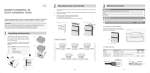
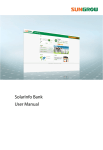
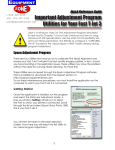
Quick Installation
Guide
SG60KU
PV Grid-connected Inverter
SG60KU-QIEN-Ver10-201412
Version: 1.0
Content
1 Unpacking and Inspection ............................. 1 2 Mounting Inverter onto the Metal Frame ..... 3 3 Electrical Connection ..................................... 5 4 Commissioning ............................................. 11 SG60KU Quick Installation Guide
This guide provides a general instruction of the installation procedures of SG60KU.
In no case shall this guide substitute for the user manual or related notes on the
device.
Make sure to read over, fully understand and strictly follow the detailed
instructions of the user manual and other related regulations before installing
the equipment.
Any violation could result in personal death or injury or device damage.
1 Unpacking and Inspection
Step 1 Remove the backplate and
fasteners from the packaging.
Step 2 Inspect the inverter for visible
damages and check the
completeness of the delivery
contents according to the
inner packing list.
Contact your supplier if any of the contents is missing. SG60KU is
unavailable if any damage is detected.
1
Fig. 1-1 Scope of delivery
2
Item
Name
A
B
C
Inverter
Backplate
Inverter cap
D
Documents
E
Fasten set
F
Fix screw
G
DC connector
Description
--Used to fix the inverter to the installation site.
For better weather-proof function of the inverter.
Quality certificate, packing list, product test report, CD
and quick user manual
Six units to fasten backplate to metal frame.
Two M4×16 screws to fix the inverter with the
backplate.
Eight pairs MC4 terminals for PV connection.
2 Mounting Inverter onto the Metal
Frame
1.
Select the installation location and regulate the clearances of multiple
inverters, referring to the user manual.
2.
Move the inverter to the installation site with the help of another person or
the lifting device by means of the handles.
3.
Install the inverter onto metal frame as following procedures.
a)
Fix the backplate on the metal frame with appropriate fixing sets.
b)
Mount the inverter onto the backplate and secure it with M4 screws.
c)
Assemble the top cap of the inverter.
3
*Supplement
If the installation location is higher, the inverter can not be directly linked to the
backplate, please perform following steps to lift the inverter to the level of the fixed
backplate or adjacent place.
Step 1 Screw two M12-screwed lifting rings to the screw holes on top of the
inverter.
M12-screwed lifting ring is a standard component. It is not within the
scope of delivery. Please purchase from the market if needed.
Step 2 Lead the rope (with sufficient load-carrying capacity) prepared beforehand
through the two lifting rings to lift the inverter. Inverter is lifted to the level of
the fixed backplate or adjacent place.
Please keep the inverter balance during the whole process of inverter
lifting. Inverter may hit the metal frame or other obstacles if otherwise.
4
3 Electrical Connection
Death hazards due to high voltage existing inside the inverter!
Make sure that all the DC and AC cables to the inverter are not live before you
start the electrical work.
Do not turn on the AC side or DC side circuit breaker until all inverter electrical
connections have completed.
3-1 Open the Connection Cabinet
Loose the six screws on the front cover of the connection cabinet and remove the
front cover to see the internal layout of the connection cabinet.
5
3-2 Cables Selection
y AC Cable
No.
Description
Remark
A
External diameter of the cable: 37~44 mm
C
Protective layer
Length of insulation
stripped off
Insulation layer
D
Cross section of AC cables
B
to
be
24 mm
Range: 25-95mm2; recommended value:
50 mm2
The following table gives the recommended max. length of the AC cables based
on the cross-section of the AC cables.
Cross-section of the AC cable (mm2)
Max. length of the AC cables (m)
25
35
50
0-50
50-100
>100
y DC Cables
Cross-sectional
area
Cable
External
diameter
Max.
withstand
voltage
6~8mm2
10AWG~8AWG
6~9mm
1000V
Max. input current for
each PV string
30A
y Second PE Cable
Cross-sectional area(mm2)
10AWG…8AWG
6mm²
Recommended conductor size(mm2)
9AWG
6mm²
y RS485 communication cables
Shielded twisted pair cables or Shielded twisted pair Ethernet cables.
6
3-3 AC Connection
Pull the cables and connect L1/L2/L3 cables ends to the corresponding terminal
blocks. Connect the PE cable ends to the clamp.
3-4 DC Connection
Step 1 Check the connection cable of PV string for the correct polarity and that the
open-circuit voltage does not exceed the inverter input limit 1000V, even
under the lowest operating temperature.
• Check the positive and negative polarity of the PV cells. After
confirmation, you can insert the DC connectors into the input terminals
on the bottom of the inverter.
• For the same MPPT, reverse connection of a single string is prohibited.
A permanent failure of the system or inverter may follow if otherwise.
7
Step 2 Connect the 2 PV strings in parallel using T-type terminals and then connect
them to inverter DC input.
-
-
+
+
+
Step 3 Insert the positive and negative DC
connectors into the input terminals on
the bottom of the inverter until there is
an audible sound.
3-5 Second Protective Earth Terminal
Inverter is equipped with second protective earth terminal as specified in EN 50178.
Position of Second PE Terminals
There is a second PE terminal on one side of the inverter. User can perform PE
connection if necessary.
8
Cable Connection
Item
Name
Description
A
Screw
M6×12mm
B
C
D
E
Lock washer
Washer
Cable socket
Yellow-green
cable
6mm2(9AWG)
* Connection parts are not within the scope of delivery
3-6 Communication Connection
There are two communication waterproof connection terminal on the bottom of the
inverter. RS485 A/B terminals, RS485 interface and Ethernet interface are provided
on the configuration circuit board of the junction box.
9
A 120Ω terminating resistor can be connected between the A and B communication
cable through the dip switch.
For RJ45 Connection the pins definitions are shown below. In Ethernet cable, Pin 3
white-green cable defines RS485- B while Pin 6 green cable defines RS485+ A.
For Ethernet Connection the pins definitions are shown below. Use the Ethernet
crimper to crimp the cables and connect cables to RJ45 plug according to TIA/EIA
568B.
3-7 Completing Installation
Inspect befor commissioning and reassemble the front cover of the connection
cabinet.
10
4 Commissioning
Before starting SG60KU, make sure all installation and connections are completed
and verified.
Step 1 Close the AC circuit breaker.
Step 2 Rotate DC switch to “ON” position.
Step 3 Suppose there are sufficient sunlight and
enough DC power. PV arrays initialize and
supply DC power to inverter. The LCD
display is activated when DC voltage
exceeds inverter startup votlage. If there is
a defect on the display, contact Sungrow.
Step 4 Press j to choose country code. Confirm
the settings by Pressing ENTER.
Step 5 Select the country code according to the
installation country of the inverter. Each
country code represents corresponding
local protective parameters that have been
preset before delivery. Before country
setting, there is warning screen. Operate
according to the warning information and
press ENTER.
If the inverter is installed where the country code is not included, please choose
item “Other” and manually set the protection parameters.
If the country code is not set correctly during commissioning, reset the
protection parameters.
11
Step 6 If the country code set as GR, a Grid
codes page as shown in the right will
appear. Press j to select grid code and
press ENTER to confirm.
If the country code set as DE, a Grid codes page
as shown in the right will appear, where LV
signifying low-voltage grid; MV signifying
medium-voltage grid. Press j to select grid
code and press ENTER to confirm.
If the country code set as TK, a Grid codes page
as shown in the right will appear. Press j to
select grid code and press ENTER to confirm.
If the country code set as TH, a Grid codes page
special for Thailand will appear. Press j to
select grid code and press ENTER to confirm.
If the country code set as Other, a Grid codes
page as shown in the right will appear. Press j
to select grid code and press ENTER to
confirm.
Step 7 If the country selected is not the
abvementioned 5 countries, enter the
next step directly.
12
Step 8 After selecting the Grid Code, there will
be a “Pro-stage” type selection screen and
then corresponding sub-menu will come
up.
Step 9 Set the inverter time as per local time.
Incorrect time setting will affect the data
logging. Press h to move the cursor and
Press j to set the specific time and date.
Press ENTER to confirm setting.
Step 10After configuring all parameters, there
will be a “setting confirmation” screen.
Check whether all above-mentioned
parameters are correct. Confirm by
Pressing ENTER. Cancel by Pressing ESC
and reset.
Step 11Inverter will enter into startup process.
Observe the status of LED indicators and
the LCD main screen. If commissioning
succeeds, the “RUN” indicator will be on
and “Run” will be displayed on the “State”
area.
If fault or warning occurs, the “FAULT” indicator will be on or the “RUN” indicator will
Flicker, and “Fault” or "Warn" will occur on the display. Press j to view “current
fault/warning” information. Remove the existing fault or warning, and then repeat
the commissioning procedures.
13