1
Notification
Dear Users,
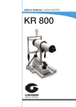
Thank you for your purchase of KR 800 Keratometer. Please take time to read our
user’s manual carefully before use.
This guarantees you to make full use of this unit and prolongs the operation life of
this unit.
Precautions
If you have detected abnormal heat, smoke, noise or smell, immediately stop using
the product.
In the event of an abnormality, turn off the power and disconnect the power plug from
the power socket. Continuing to use the product may result in electric shock or fire.
Observe the instructions given below regarding the power cable:
•
•
•
•
•
•
Be sure to use the supplied or specified power cable.
Do not modify, forcibly bend, kink or pull the power cable.
When disconnecting the power cable from the AC outlet, be sure to hold the cable
by the plug.
Pulling the cable may cause wire breakage or shot circuit, resulting in fire or electric
shock.
Do not connect or disconnect the plug of the power cable to/from the AC outlet
using wet hands.
Doing so may result in electric shock.
Do not touch the product with wet hands while the power cable is connected
to the AC outlet.
Doing so may result in electric shock.
If the product will not be used for a long period, disconnect the power cable
from the power source. Leaving the cable connected to the power socket for
a prolonged period will consume electricity and may result in heating.
Content
1.
Function Introduction .....................................................................................4
2.
Name of Parts ...............................................................................................4
3.
Accessories ...................................................................................................6
4.
Functions ......................................................................................................6
5.
Examination ...................................................................................................6
6.
Maintenance ..................................................................................................7
7.
Precaution .....................................................................................................8
8.
Common Trouble Shooting ...........................................................................9
9.
Specifications ...............................................................................................10
1. Function Introduction
Keratometer was developed under the guidance of Optometry Center. This instrument
can give a precise examination of the radius of curvature of the anterior corneal
surface. This measurement is utilized to fit contact lenses and to monitor corneal
changes produced through the wear of contact lenses. Keratometer are occasionally
used to assist in the recognition of certain corneal abnormalities and to check the
radii of curvature of both hard and soft contact lenses. The program can be operated
with considerable ease.
2. Name of Parts
1.
Protractor scale
Indicates the axis of astigmatism.
2.
Adjustable eyepiece control
Adjustable from to diapers to correct for operator spherical error.
3.
Horizontal knob
4.
Axis rotating handle
Must be turned to locate the axis of astigmatism when there is horizontal
Displacement of the + and - mire images.
5.
Vertical knob
Is revolved to coincide the +and +marks of the mire images for finding the radius
of curvature of the vertical axis. Vertical -, horizontal and height adjustment
improve performance and focus correctly
6.
Operating Rod
7.
Up-Down adjustable knob
Height of Up-Down adjustable for accurate positioning
8.
Power switch
9.
Fluctuation Hand-wheel
Is revolved to coincide the-and-marks of the mire images for finding the radius
of the horizontal axis
4
10.
Chin-rest
11.
Lamp-house
12.
Glare shield
Helps to maintain fixation by blocking of no measured eye.
13.
Headrest
13
12
1
11
2
10
3
4
9
5
6
7
8
5
3. Accessories
1.
2.
3.
4.
5.
Standard balls: R7.15, R9, RIO.
Wording lamp (12v 10w): five
Standard ball measurement unit
Instruction: one
Conformity certification: one
4. Functions
1.
The instrument efficiently measures the radius of curvature of the anterior corneal
surface.
One posicion measurement is not only more accurate but is truly effective in
reducing measuring time and also helps promote patient’s cooperation.
The brightness of all three images is equal. The central image is double whenever
the instrument is not focused precisely on the corneal mire image. This allows
continuous monitoring of correct focus by the examiner.
2.
Internal scale reading system. Beside the mire images, the millimeter scales for
the radius of curve.
Radius of curvature and the diaper scales for corneal refractive power are view
at all times in the field of view.
3.
Measurement of corneal astigmatism
Horizontal displacement of the mire images indicates existence of astigmatism
and axis rotating handle is used to coincide the measuring head with axis, after
which the vertical and horizontal knobs are used to coincide the mire images,
showing the great case and simplicity of one position measurement.
5. Examination
Preparation
Use the Keratometer in a quite, darkened room, in order to keep the patients
overcomes any apprehension about the examination. Fully explain the purpose and
procedure of the examination before starting. Follow the produce as shown below
to make the necessary preparations.
1.
Verify the ovular surface of both eyes.
6
2.
Connect the instrument power plug to the outlet.
3.
Tura power switch on.
4.
Seat the patient at the Keratometer to allow for the adaptation to the examination.
5.
Adjust both the height of the chair and instrument to assure maximum comfort
for the patient.
6.
Place the patients chin in the chinrest by using the chinrest height control.
Center the patient’s pupil in the systems axis when the patient will see his
reflected eye image in the instrument.
7.
Occlude the eye, which is not being tested.
8.
When the occasion demands, use the headband to secure the patient’s head
in the chinrest assembly.
Examination
1.
Figure 3 the central image is double, indicating that the instrument is not
correctly focused on the central image. Use the adjustment control to bring
the central double image into clear one.
2.
Figure sows the view seen when instrument is in focus, the vertical doubling
and the horizontal and the doubling is insufílcient. Adjustment of the vertical
knob and the horizontal knob would bring the two minus signs and the two
plus into coincidence tow.
3.
Figure 5 illustrates the view seen when oblique stigmatism is present.The entire
instrument has been rotated slightly toward the axis of the astigmatism, but the
two plus signs are not yet in alignment with each other. Further rotation would
accomplish this alignment. Figure 6 Adjustment of the horizontal measurement
control would bring the two plus signs, into coincidence. In the same way,
adjusting the vertical measurement control would bring the minus signs, B and
Bingo coincidence.
4.
The vertical and horizontal degrees of doubling are correct.
Readings
1.
When the instrument is correctly aligned. Record the ready form the diagrams
beside the images Fig-7.
7
2.
When oblige sating mates is present record the degree of rotation instrument.
6. Maintenance
1.
The instrument should be avoided from any strong vibration or shock.
2.
Measure the standard balls at regular to make the instrument accuracy.
3.
Cover the instrument to keep it form dust when not used.
4.
A rubber blower is provided to assist in removing dust, if the dust remains, a
soft bristled brush may be utilized.
7. Precaution
1.
The instrument should be placed in an area that will be free of excessive
Temperature and humidity. The room should have adequate humidity. Be free
of dust the instrument should not be in direct sunlight.
2.
The instrument should be installed in a table position. Avoiding any vibrations
or shock.
3.
The correct current voltage and frequency must be used.
4.
All cords should be correctly connected.
5.
The instrument should be properly grounded.
6.
Proper comfort patient position is essential for an effective exam.
7.
When disconnecting any cable, never use excessive force and do not attempt
to disconnect any cable by pulling on the cord itself.
8.
In the event that the instrument requires any service, contact your authorized
distributor. Only qualified service personnel should make repairs.
9.
Any modification to the unit may affect its performance, as well as voiding the
warranty.
8
8. Common Trouble Shooting
Symptoms
Cause
1. No mire image
Has the fuse blown?
2. Head scale image damaged
Main lamp damaged?
Has the scale lamp?
3. Head rest does not move up
or down
The rod of headrest needs Grease?
9
9. Specifications
Range of corneal radius of curvature
5.5-11mm
Range of corneal refractive power
35-68D
Power
110V, SOW
Axis of corneal astigmatism
0 -180°
Head-rest Adjustment range
90
Mainframe volume
300x280x510 mm3
10
LUXVISION is not responsible or liable for indirect, special or consequential damages arising out of or in
connection with the use or performance of the product or damages with respect to any economic loss,
loss of property, loss of revenues or profits, loss of enjoyment or use, costs of removal or installation or
other consequential damages of whatsoever nature. Some states do not allow the exclusion or limitation
of incidental or consequential damages. Accordingly, the above limitation may not apply to you.
Every effort has been made to ensure the accuracy of this manual. However, LUXVISION, makes no
warranties with respect to the documentation and disclaims any implied warranties of merchantability
and fitness for a particular purpose. LUXVISION, Inc. shall not be liable for any errors or for incidental or
consequential damages in connection with the furnishing, performance, or use of this manual or the examples
herein. The information in this document is subject to change without notice.
11