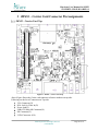
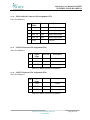
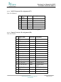
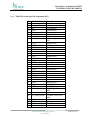
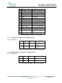
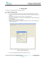
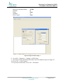
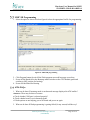
1
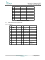
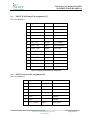
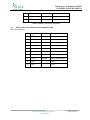
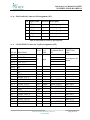
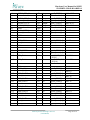
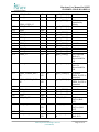
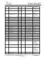
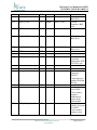
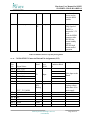
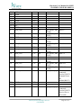
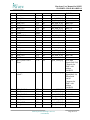
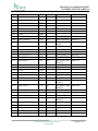
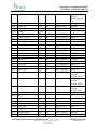
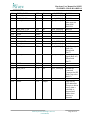
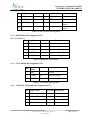
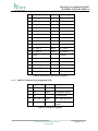
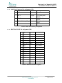
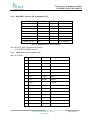
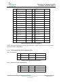
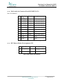
Hardware User Manual for iMX53 Carrier Card iW-PRDTL-UM-02-R1.0-REL1.1 Hardware User Manual for iMX53 Carrier Card iW-PRDTL-UM-02-R1.0-REL1.1 10th July, 2011 IMX53-Carrier Card Hardware User Manual iWave Systems Technologies Pvt. Ltd. (Confidential) Page 1 of 74 Hardware User Manual for iMX53 Carrier Card iW-PRDTL-UM-02-R1.0-REL1.1 DOCUMENT IDENTIFICATION Project Name iW-RAINBOW-G11D Document Name iW-PRDTL-UM-02-R1.0-REL1.0-Rainbow G11 HW Usermanual Document Home file://server/prdtl/svn/trunk/iW-PRDTL-PF-02-R1.0/iW-PRDTL-HF-02-R1.0/iWPRDTL-UM-02-R1.0 Release No REL 1.1 Status Release Audience DOCUMENT REVISION HISTORY Revision 1.0 1.1 Date 5 Jul 2011 10th Jul 2011 th Change Description Initial Draft Release Updated Connector details Updated By Madhavan Madhavan Reviewed By Roshan D‟souza Roshan D‟souza PROPRIETARY NOTICE: This document contains proprietary material for the sole use of the intended recipient(s). Do not read this document further if you are not the intended recipient. Any review, use, distribution or disclosure by others is strictly prohibited. If you are not the intended recipient (or authorized to receive for the recipient), you are hereby notified that any disclosure, copy or distribution or use of any of the information contained within this document is STRICTLY PROHIBITED. Thank you. “iWave Systems Tech. Pvt. Ltd.”s iWave Systems Technologies Pvt. Ltd. (Confidential) Page 2 of 74 Hardware User Manual for iMX53 Carrier Card iW-PRDTL-UM-02-R1.0-REL1.1 TABLE OF CONTENTS 1 INTRODUCTION .................................................................................................................. 8 PURPOSE ............................................................................................................................. 8 SCOPE ................................................................................................................................. 8 GLOSSARY .......................................................................................................................... 8 2 HARDWARE DETAILS ....................................................................................................... 9 IMX53 – CARRIER CARD CONNECTOR DETAILS ................................................................. 9 HARDWARE SETUP DETAILS ............................................................................................. 12 2.2.1 Power Supply Connection Procedure ....................................................................... 12 2.2.2 Serial Cable Connection Procedure .......................................................................... 13 2.2.3 USB OTG Connection Procedure ............................................................................. 14 2.2.4 SD2/MMC Connection Procedure ............................................................................ 15 2.2.5 Audio In Cable Connection Procedure ..................................................................... 16 2.2.6 Audio Out Cable Connection Procedure................................................................... 17 2.2.7 VGA Cable Connection Procedure ........................................................................... 18 2.2.8 Ethernet Cable Connection Procedure ...................................................................... 19 2.2.9 USB Host 1 Connection Procedure........................................................................... 20 2.2.10 USB Host 2 Connection Procedure........................................................................... 21 2.2.11 USB Host 3 Connection Procedure........................................................................... 22 2.2.12 CAN Connection Procedure ..................................................................................... 23 2.2.13 SATA Connection Procedure ................................................................................... 24 3 IMX53 – CARRIER CARD CONNECTOR PIN ASSIGNMENTS ............................... 25 IMX53 – CARRIER CARD TOP .......................................................................................... 25 IMX53 – CARRIER CARD BOTTOM ................................................................................... 27 3.2.1 3.2.2 3.2.3 3.2.4 3.2.5 3.2.6 3.2.7 3.2.8 3.2.9 3.2.10 3.2.11 3.2.12 3.2.13 3.2.14 VGA Connector Pin Assignment (J1) ...................................................................... 29 RCA Jack for Video In Pin Assignment (J2) ............................................................ 30 Power Jack Pin Assignment (J3)............................................................................... 30 USB OTG Mini AB Connector Pin Assignment (J4) ............................................... 30 SD Connector Pin Assignment (J5) .......................................................................... 30 LVDS Connector Pin Assignment (J6) ..................................................................... 31 MOST JTAG Header Pin Assignment (J7) .............................................................. 32 MOST Conncetor Pin Assignment (J9) .................................................................... 32 ESAI Audio Out Connector Pin Assignment (J10) .................................................. 33 ESAI Audio In Connector Pin Assignment (J11) ..................................................... 34 314 Pin MXM 3 Connector Top Pin Assignments (J12) .......................................... 34 314 Pin MXM 3 Connector Bottom Pin Assignments (J12) .................................... 40 LVDS Connector Pin Assignment (J13) ................................................................... 46 MLB Header Pin Assignment (J14).......................................................................... 47 iWave Systems Technologies Pvt. Ltd. (Confidential) Page 3 of 74 3.2.15 3.2.16 3.2.17 3.2.18 3.2.19 3.2.20 3.2.21 3.2.22 3.2.23 3.2.24 3.2.25 3.2.26 3.2.27 3.2.28 3.2.29 3.2.30 3.2.31 3.2.32 3.2.33 3.2.34 3.2.35 3.2.36 3.2.37 3.2.38 3.2.39 3.2.40 3.2.41 3.2.42 3.2.43 4 CAN2 Header Pin Assignment (J16) ........................................................................ 47 22 Pin SATA Connector Pin Assignment (J17) ....................................................... 47 Audio In Connector Pin Assignment (J18) ............................................................... 48 Audio Out Connector Pin Assignment (J19) ............................................................ 49 RJ45 MAGJACK Pin Assignment (J20) .................................................................. 49 Dual DB9 Connector Pin Assignment (J21) ............................................................. 50 HDMI Connector Pin Assignment (J22)................................................................... 50 USB Type A Connector Pin Assignment (J23) ........................................................ 51 Expansion Connector Pin Assignment (J24) ............................................................ 51 Video Input Header Pin Assignment (J26) ............................................................... 53 SIM Connector Pin Assignment (J27) ...................................................................... 53 UART5 Connector Pin Assignment (J29) ................................................................ 54 SPDIF IN Connector Pin Assignment (J30) ............................................................. 54 ESAI Audio Out Connector Pin ASSIGNMENT (J31) ............................................ 55 RTC Battery Header Pin Assignment (J32) .............................................................. 55 ESAI Audio In Connector Pin Assignment (J33) ..................................................... 56 UART4 Connector Pin Assignment (J34) ................................................................ 56 UART3 Connector Pin Assignment (J36) ................................................................ 56 UART2 Connector Pin Assignment (J37) ................................................................ 57 Camera Connector Pin Assignment (J38) ................................................................. 57 WIFI Module Connector Pin Assignment (J39) ....................................................... 58 LCD Connector Pin Assignment (J40) ..................................................................... 59 Mini PCIe Connector Pin Assignment (J41) ............................................................ 61 Left Speaker Connector Pin Assignment (J42) ......................................................... 62 Right Speaker Connector Pin Assignment (J43) ...................................................... 62 Resistive Touch Connector Pin Assignment (J44) ................................................... 63 2G Module Connector Pin Assignment (J45) ........................................................... 63 MIC Connector Pin Assignment (J46) ...................................................................... 63 7 Pin SATA Connector Assignment (J47) ................................................................ 64 POWER ON .......................................................................................................................... 65 HYPERTERMINAL SETUP .................................................................................................. 65 5 ATK USER MANUAL......................................................................................................... 69 INSTALLING ADVANCED TOOL KIT................................................................................... 69 INITIAL SETUP OF ADVANCED TOOL KIT .......................................................................... 69 MMC/SD PROGRAMMING ................................................................................................ 72 ATK-FAQS: ..................................................................................................................... 72 6 TECHNICAL SUPPORT .................................................................................................... 74 Hardware User Manual for iMX53 iW-PRDTL-UM-02-R1.0-REL1.0 LIST OF FIGURES FIGURE 1:IMX53-CARRIER CARD CONNECTOR DETAILS-1 ............................................................. 9 FIGURE 2:IMX53-CARRIER CARD CONNECTOR DETAILS-2 ........................................................... 10 FIGURE 3: IMX53-CARRIER CARD CONNECTOR DETAILS-3 .......................................................... 11 FIGURE 4: IMX53-CARRIER CARD POWER CONNECTION .............................................................. 12 FIGURE 5: SERIAL PORT CONNECTION ........................................................................................... 13 FIGURE 6: USB DEVICE CONNECTION ........................................................................................... 14 FIGURE 7: SD CONNECTION ........................................................................................................... 15 FIGURE 8: AUDIO IN CONNECTION ................................................................................................. 16 FIGURE 9: AUDIO OUT CONNECTION ............................................................................................. 17 FIGURE 10: VGA CABLE CONNECTION.......................................................................................... 18 FIGURE 11: ETHERNET CONNECTION ............................................................................................. 19 FIGURE 12: USB HOST1 CONNECTION........................................................................................... 20 FIGURE 13: USB HOST 2 CONNECTION .......................................................................................... 21 FIGURE 14: USB HOST 3 CONNECTION .......................................................................................... 22 FIGURE 15: CAN CONNECTION...................................................................................................... 23 FIGURE 16: SATA CONNECTION.................................................................................................... 24 FIGURE 17: IMX53 – CARRIER CARD TOP ..................................................................................... 25 FIGURE 18: IMX53 – CARRIER CARD BOTTOM .............................................................................. 27 FIGURE 19: HYPERTERMINAL SETTINGS-1 ..................................................................................... 65 FIGURE 20: HYPERTERMINAL SETTINGS-2 ..................................................................................... 66 FIGURE 21: ENABLE ECHO TYPED CHARACTERS ............................................................................ 67 FIGURE 22: UART CONSOLE WINDOW.......................................................................................... 68 FIGURE 23: BOOTSTRAP SWITCH.................................................................................................... 69 FIGURE 24: ATK TOOLKIT SETTINGS ............................................................................................ 70 FIGURE 25: FLASH TOOL SELECTION ............................................................................................. 71 FIGURE 26: MMC/SD PROGRAMMING ........................................................................................... 72 iWave Systems Technologies Pvt. Ltd. (Confidential) Page 5 of 74 Hardware User Manual for iMX53 iW-PRDTL-UM-02-R1.0-REL1.0 List of Tables TABLE 1: GLOSSARY .............................................................................................................................. 8 TABLE 2: RS232 PORT PIN ASSIGNMENT .............................................................................................. 13 TABLE 3: USB OTG CONNECTOR PIN ASSIGNMENT ............................................................................. 14 TABLE 4: CAN PORT PIN ASSIGNMENT ................................................................................................. 23 TABLE 5: VGA CONNECTOR PIN ASSIGNMENT ..................................................................................... 29 TABLE 6: RCA JACK PIN ASSIGNMENT ................................................................................................. 30 TABLE 7: POWER JACK PIN ASSIGNMENT ............................................................................................. 30 TABLE 8: USB MINI AB CONNECTOR PIN ASSIGNMENT ...................................................................... 30 TABLE 9: SD CONNECTOR PIN ASSIGNMENT ........................................................................................ 31 TABLE 10: LVDS CONNECTOR1 PIN ASSIGNMENT ............................................................................... 31 TABLE 11: MOST JTAG HEADER PIN ASSIGNMENT ............................................................................ 32 TABLE 12: MOST CONNECTOR PIN ASSIGNMENT ................................................................................ 33 TABLE 13: ESAI AUDIO OUT CONNECTOR PIN ASSIGNMENT ............................................................... 33 TABLE 14: ESAI AUDIO IN CONNECTOR PIN ASSIGNMENT .................................................................. 34 TABLE 15: MXM3 CONNECTOR TOP SIDE PIN ASSIGNMENT ................................................................ 40 TABLE 16: MXM3 CONNECTOR BOTTOM SIDE PIN ASSIGNMENT ........................................................ 46 TABLE 17: LVDS CONNECTOR2 PIN ASSIGNMENT ............................................................................... 47 TABLE 18: MLB HEADER PIN ASSIGNMENT ......................................................................................... 47 TABLE 19: CAN2 HEADER PIN ASSIGNMENT ....................................................................................... 47 TABLE 20: 22 PIN SATA CONNECTOR PIN ASSIGNMENT ...................................................................... 48 TABLE 21: AUDIO IN PIN ASSIGNMENT ................................................................................................. 48 TABLE 22: AUDIO OUT CONNECTOR PIN ASSIGNMENT......................................................................... 49 TABLE 23: RJ45 MAGJACK PIN ASSIGNMENT ................................................................................... 49 TABLE 24: DUAL DB9 CONNECTOR PIN ASSIGNMENT ......................................................................... 50 TABLE 25: HDMI CONNECTOR PIN ASSIGNMENT ................................................................................ 51 TABLE 26: USB TYPE A CONNECTOR PIN ASSIGNMENT ...................................................................... 51 TABLE 27: EXPANSION CONNECTOR PIN ASSIGNMENT ........................................................................ 53 TABLE 28: VIDEO INPUT HEADER PIN ASSIGNMENT ............................................................................ 53 TABLE 29: SIM CONNECTOR PIN ASSIGNMENT .................................................................................... 54 TABLE 30: UART5 CONNECTOR PIN ASSIGNMENT .............................................................................. 54 TABLE 31: SPDIF IN CONNECTOR PIN ASSIGNMENT ........................................................................... 54 TABLE 32: ESAI AUDIO OUT CONNECTOR PIN ASSIGNMENT .............................................................. 55 TABLE 33: RTC HEADER PIN ASSIGNMENT.......................................................................................... 55 TABLE 34: ESAI AUDIO IN CONNECTOR PIN ASSIGNMENT .................................................................. 56 TABLE 35: UART4 CONNECTOR PIN ASSIGNMENT .............................................................................. 56 TABLE 36: UART3 CONNECTOR PIN ASSIGNMENT .............................................................................. 56 TABLE 37: UART2 CONNECTOR PIN ASSIGNMENT .............................................................................. 57 TABLE 38: CAMERA CONNECTOR PIN ASSIGNMENT ............................................................................. 58 TABLE 39: WIFI MODULE CONNECTOR PIN ASSIGNMENT ................................................................... 58 iWave Systems Technologies Pvt. Ltd. Page 6 of 74 (Confidential) TABLE 40: 7” FORMIKE LCD CONNECTOR PIN ASSIGNMENT ............................................................... 60 TABLE 41: MINI PCIE CONNECTOR PIN ASSIGNMENT .......................................................................... 62 TABLE 42: LEFT SPEAKER OUTPUT CONNECTOR PIN ASSIGNMENT...................................................... 62 TABLE 43: LEFT SPEAKER OUTPUT CONNECTOR PIN ASSIGNMENT...................................................... 62 TABLE 44: RESISTIVE TOUCH CONNECTOR PIN ASSIGNMENT .............................................................. 63 TABLE 45: 2G MODULE CONNECTOR PIN ASSIGNMENT ....................................................................... 63 TABLE 46: MIC CONNECTOR PIN ASSIGNMENT ................................................................................... 63 TABLE 47: 7 PIN SATA CONNECTOR PIN ASSIGNMENT ....................................................................... 64 Hardware User Manual for iMX53 iW-PRDTL-UM-02-R1.0-REL1.0 1 Introduction Purpose The purpose of this document is to explain the procedure about the user interface, Power ON procedure and ATK tool kit usage for iMX53-Carrier Card. Scope This document describes the Hardware details, Power-on procedure and setting up Serial communication with PC/Laptop. This document also explains usage procedure for ATK tool kit. Glossary Table 1: Glossary Acronyms ATK CAN LCD DDR FAQ HT MMC PC RS232 SATA SD UART USB VGA Description. Advanced Tool Kit Controller Area Network Liquid Crystal Display Double Data Rate Frequently Asked Question Hyper Terminal Multi Media Card Personal computer Recommended Standard 232 Serial Advanced Technology Attachment Secure Digital Universal Asynchronous Receiver Transmitter Universal Serial Bus Video graphic Array iWave Systems Technologies Pvt. Ltd. (Confidential) Page 8 of 74 Hardware User Manual for iMX53 iW-PRDTL-UM-02-R1.0-REL1.0 2 Hardware Details iMX53 – Carrier Card Connector details Figure 1:iMX53-Carrier Card Connector Details-1 iWave Systems Technologies Pvt. Ltd. (Confidential) Page 9 of 74 Hardware User Manual for iMX53 iW-PRDTL-UM-02-R1.0-REL1.0 Figure 2:iMX53-Carrier Card Connector Details-2 iWave Systems Technologies Pvt. Ltd. (Confidential) Page 10 of 74 Hardware User Manual for iMX53 iW-PRDTL-UM-02-R1.0-REL1.0 Figure 3: iMX53-Carrier Card Connector Details-3 iWave Systems Technologies Pvt. Ltd. (Confidential) Page 11 of 74 Hardware User Manual for iMX53 iW-PRDTL-UM-02-R1.0-REL1.0 Hardware Setup Details Power Supply Connection Procedure Insert the power plug of the power supply provided into the power jack of the iMX53-Carrier Card as shown below. 2.2.1 Power Rating: 5V input with 2.5A. Figure 4: iMX53-Carrier Card Power Connection iWave Systems Technologies Pvt. Ltd. (Confidential) Page 12 of 74 Hardware User Manual for iMX53 iW-PRDTL-UM-02-R1.0-REL1.0 Serial Cable Connection Procedure 1. Serial cable provided has DB9 connector (Female type) at both end. 2.2.2 2. Insert DB9 of the serial cable to PC/Laptop COM port. 3. Connect other end of the serial cable to iMX53 carrier board serial port connector (Bottom) as shown below. Figure 5: Serial Port Connection The RS232 port pin outs are as in below table. Table 2: RS232 port pin assignment Pin No 2 3 5 1,4,6,7,8,9 Signal Name RXD TXD GND NC Description Receive Data(Input) Transmit Data (Output) Ground No connection iWave Systems Technologies Pvt. Ltd. (Confidential) Page 13 of 74 Hardware User Manual for iMX53 iW-PRDTL-UM-02-R1.0-REL1.0 USB OTG Connection Procedure Insert the USB Device Mini B cable to the USB OTG connector as shown below & other end to HOST PC/Laptop. 2.2.3 Figure 6: USB Device Connection The USB OTG connector pin outs are as in below table. Table 3: USB OTG connector pin assignment Pin No 1 Signal Name VBUS_OTG 2 USB_OTG_DATA- 3 USB_OTG_DATA+ 4 5 USB_ID GND Description VBUS Supply Data pair (IO) USB ID pin Float to act as a Device GND to act as a Host Ground iWave Systems Technologies Pvt. Ltd. (Confidential) Page 14 of 74 Hardware User Manual for iMX53 iW-PRDTL-UM-02-R1.0-REL1.0 SD2/MMC Connection Procedure Insert the SD Memory card in the 4 bit SD slot as shown below. 2.2.4 Figure 7: SD Connection iWave Systems Technologies Pvt. Ltd. (Confidential) Page 15 of 74 Hardware User Manual for iMX53 iW-PRDTL-UM-02-R1.0-REL1.0 Audio In Cable Connection Procedure Insert the Audio IN jack into the Audio in connector as shown below. 2.2.5 Note: Here the RED color cable is used to denote the audio input. Figure 8: Audio In Connection iWave Systems Technologies Pvt. Ltd. (Confidential) Page 16 of 74 Hardware User Manual for iMX53 iW-PRDTL-UM-02-R1.0-REL1.0 Audio Out Cable Connection Procedure Insert the Audio OUT jack into the Audio out connector as shown below. 2.2.6 Note: Here the Black color cable is used to denote the audio output. Figure 9: Audio Out Connection iWave Systems Technologies Pvt. Ltd. (Confidential) Page 17 of 74 Hardware User Manual for iMX53 iW-PRDTL-UM-02-R1.0-REL1.0 VGA Cable Connection Procedure Insert the VGA cable carefully into the into the VGA (DB15) connector. While removing the cable hold the VGA connector & then pull out the cable carefully. 2.2.7 Figure 10: VGA Cable Connection iWave Systems Technologies Pvt. Ltd. (Confidential) Page 18 of 74 Hardware User Manual for iMX53 iW-PRDTL-UM-02-R1.0-REL1.0 Ethernet Cable Connection Procedure Insert the Ethernet cable into the RJ-45 Magjack connector as shown below. 2.2.8 Ignore the Green color LED glowing on the connector before inserting the cable. Figure 11: Ethernet Connection iWave Systems Technologies Pvt. Ltd. (Confidential) Page 19 of 74 Hardware User Manual for iMX53 iW-PRDTL-UM-02-R1.0-REL1.0 USB Host 1 Connection Procedure Insert the USB device (ex : USB cable) to the USB Host1 connector (Standard Type A) as shown below. 2.2.9 Figure 12: USB Host1 Connection iWave Systems Technologies Pvt. Ltd. (Confidential) Page 20 of 74 Hardware User Manual for iMX53 iW-PRDTL-UM-02-R1.0-REL1.0 USB Host 2 Connection Procedure Insert the USB device (ex : USB cable) to the USB Host 2 connector (Standard Type A) as shown below. 2.2.10 Figure 13: USB Host 2 Connection iWave Systems Technologies Pvt. Ltd. (Confidential) Page 21 of 74 Hardware User Manual for iMX53 iW-PRDTL-UM-02-R1.0-REL1.0 USB Host 3 Connection Procedure Insert the USB device (ex : USB cable) to the USB Host 3 connector (Standard Type A) as shown below. 2.2.11 Figure 14: USB Host 3 Connection iWave Systems Technologies Pvt. Ltd. (Confidential) Page 22 of 74 Hardware User Manual for iMX53 iW-PRDTL-UM-02-R1.0-REL1.0 CAN Connection Procedure CAN Devices can be connected to the CAN port (TOP) provided as shown below. 2.2.12 Figure 15: CAN Connection The connector pin outs are shown in below table. Table 4: CAN port pin assignment Pin No 2 7 3,6 1,4,5,8,9 Signal Name CAN1H CAN1L GND NC Description Dominant High Dominant Low Ground No connection iWave Systems Technologies Pvt. Ltd. (Confidential) Page 23 of 74 Hardware User Manual for iMX53 iW-PRDTL-UM-02-R1.0-REL1.0 SATA Connection Procedure Insert the 2.5” SATA HDD to the 22 pin SATA connector as shown below. Presently only 5V @1A supply is provided through the connector, since almost all the 2.5” SATA HDD requires only 5V. 2.2.13 Figure 16: SATA Connection iWave Systems Technologies Pvt. Ltd. (Confidential) Page 24 of 74 Hardware User Manual for iMX53 iW-PRDTL-UM-02-R1.0-REL1.0 3 iMX53 – Carrier Card Connector Pin Assignments iMX53 – Carrier Card Top Figure 17: iMX53 – Carrier Card Top Above Figure Shows the Carrier card connector reference numbers on top side. Following are the list of Connectors on Top.side VGA Connector(J1) RCA Jack for Video In(J2) Power Jack(J3) USB OTG Mini AB Connector(J4) SD Connector(J5) LVDS Connector-1(J6) iWave Systems Technologies Pvt. Ltd. (Confidential) Page 25 of 74 Hardware User Manual for iMX53 iW-PRDTL-UM-02-R1.0-REL1.0 MOST JTAG Header( J7) MOST Connector(J9) 10pin_50mil header for ESAI Audio out(J10) 5pin_50mil header for ESAI Audio In(J11) 314 Pin MXM 3 RVS Connector(J12) LVDS Connector-0(J13) MLB Header(J14) CAN2 Header(J16) 22 Pin SATA Connector(J17) Audio In Jack(J18) Audio Out Jack(J19) RJ45/MagJack(J20) Dual DB9 Connector( J21) HDMI Connector(J22) USB Type A Connector(J23) iWave Systems Technologies Pvt. Ltd. (Confidential) Page 26 of 74 Hardware User Manual for iMX53 iW-PRDTL-UM-02-R1.0-REL1.0 iMX53 – Carrier Card Bottom Figure 18: iMX53 – Carrier Card Bottom Above Figure Shows the Carrier card connector reference numbers on bottom side. Following are the list of Connectors on Bottom.side . Expansion Connector(J24) Battery Charging Header(J25) 2 Pin Header For Video In(J26) SIM Connector(J27) iWave Systems Technologies Pvt. Ltd. (Confidential) Page 27 of 74 Hardware User Manual for iMX53 iW-PRDTL-UM-02-R1.0-REL1.0 FAN Circuit Header(J28) 3 Pin Header for UART5 interface(J29) 3 Pin_50mil Header for SPDIF Interface(J30) 10pin_50mil Header for ESAI Audio out(J31) 2 Pin Header for RTC Battery(J32) 5pin_50mil Header For ESAI Audio In(J33) 3 Pin Header for UART4 interface(J34) Camera Connector(J35) 3 Pin Header for UART3 interface(J36) 5 Pin_50mil Header for UART2 Interface(J37) Camera Connector(J38) WIFI Module Connector(J39) LCD Connector(J40) PCIe Connector(J41) 2 Pin Header for Speaker Out Left(J42) 2 Pin Header for Speaker Out Right(J43) Touch Connector(J44) 2G Module Connector(J45) MIC Connector(J46) 7-Pin SATA Connector(J47) iWave Systems Technologies Pvt. Ltd. (Confidential) Page 28 of 74 Hardware User Manual for iMX53 iW-PRDTL-UM-02-R1.0-REL1.0 3.2.1 VGA Connector Pin Assignment (J1) Pin Signal Name 1 TV_IOR Direction Description Output Red Signal 2 TV_IOG Output Green Signal 3 TV_IOB Output Blue Signal 4 NC No Connection 5 GND Ground 6 GND Ground 7 GND Ground 8 GND Ground 9 VCC_5V 10 GND Ground 11 NC No Connection 12 I2C2_DATA IO I2C2 Data 13 HSYNC Output 14 VSYNC Output 15 I2C2_CLK IO Horizontal Synchronization Vertical Synchronization I2C2 Clock 16 SHLD1 Sheilding1 17 SHLD2 Sheilding2 Power 5V Power Table 5: VGA Connector pin assignment iWave Systems Technologies Pvt. Ltd. (Confidential) Page 29 of 74 Hardware User Manual for iMX53 iW-PRDTL-UM-02-R1.0-REL1.0 RCA Jack for Video In Pin Assignment (J2) Note: Not Mounted Pin Signal Name Description 3.2.2 1 GND Ground 2 VIDEO_IN_A TV Input 3 GND Ground 4 GND Ground Table 6: RCA Jack pin assignment 3.2.3 Power Jack Pin Assignment (J3) Pin Signal Name Description 1 VCC_IN Input Power (5V) 2 GND Ground 3 GND Ground Table 7: Power Jack pin assignment 3.2.4 USB OTG Mini AB Connector Pin Assignment (J4) Pin No Signal Name Direction Description 1 VBUS_OTG 2 USB_OTG_DATA- IO Data Port - 3 USB_OTG_DATA+ IO Data Port + 4 USB_ID Input Identification 5 GND OTG Power Ground Table 8: USB Mini AB Connector pin assignment 3.2.5 SD Connector Pin Assignment (J5) Pin Signal Name Direction Description 1 SD1_DATA3 IO Data3 Signal 2 SD1_CMD IO Command Signal 3 GND Ground iWave Systems Technologies Pvt. Ltd. (Confidential) Page 30 of 74 Hardware User Manual for iMX53 iW-PRDTL-UM-02-R1.0-REL1.0 4 VCC_3V3 Power 3.3V power 5 SD1_CLK Output Clock signal 6 GND 7 SD1_DATA0 IO Data0 8 SD1_DATA1 IO Data1 9 SD1_DATA2 IO Data2 10 SD1_CD Input Card Detect 11 GND 12 SD_WP Ground Ground Input Write Protect Table 9: SD Connector pin assignment LVDS Connector Pin Assignment (J6) Note: Not Mounted 3.2.6 Pin Signal Name 1 VCC_3V3 Direction Pin Signal Name Direction Power 11 LVDS1_2- Output Power 12 LVDS1_2+ Output 2 VCC_3V3 3 GND 13 GND 4 GND 14 LVDS1_CLK- Output 5 LVDS1_0- Output 15 LVDS1_CLK+ Output 6 LVDS1_0+ Output 16 GND 7 GND 17 LVDS1_3- Output 8 LVDS1_1- Output 18 LVDS1_3+ Output 9 LVDS1_1+ Output 19 10 GND 20 MODE_LVDS1 Pull up/down option SC_LVDS1 Pull up/down option Table 10: LVDS Connector1 pin assignment iWave Systems Technologies Pvt. Ltd. (Confidential) Page 31 of 74 Hardware User Manual for iMX53 iW-PRDTL-UM-02-R1.0-REL1.0 MOST JTAG Header Pin Assignment (J7) Note: Not Mounted 3.2.7 Pin Signal Name Direction Description 1 NC No Connection 2 GND Ground 3 NC No Connection 4 GPIO3_20 5 GND 6 VCC_3V3 Power 3.3V Supply 7 JTAG_TDI Input Test data input 8 JTAG_TCK Input Test clock 9 VCC_3V3 Power 3.3V Supply 10 GND 11 JTAG_TDO 12 B_RESET_OUTn Output Reset signal 13 NC No Connection 14 JTAG_TMS IO GPIO Ground Ground Output Input Test data output Test mode select Table 11: MOST JTAG Header pin assignment MOST Conncetor Pin Assignment (J9) Note: Not Mounted 3.2.8 Pin Signal Name Direction Description 1 TX Output Transmit signal 2 FOT_TXVCC Power Transmit Power 3 NC 4 FOT_RXVCC 5 GND Ground 6 GND Ground 7 FOT_STATn NC Power Input Receive Power Status input iWave Systems Technologies Pvt. Ltd. (Confidential) Page 32 of 74 Hardware User Manual for iMX53 iW-PRDTL-UM-02-R1.0-REL1.0 8 GND 9 RX 10 GND Ground Input Receive signal Ground Table 12: MOST Connector pin assignment ESAI Audio Out Connector Pin Assignment (J10) Note: Not Mounted 3.2.9 Pin Signal Name Direction Description 1 AOUT_1 Output Audio output signal 2 AOUT_2 Output Audio output signal 3 AOUT_3 Output Audio output signal 4 AOUT_4 Output Audio output signal 5 AOUT_5 Output Audio output signal 6 AOUT_6 Output Audio output signal 7 AOUT_7 Output Audio output signal 8 AOUT_8 Output Audio output signal 9 GND GND 10 GND GND Table 13: ESAI Audio Out Connector pin assignment iWave Systems Technologies Pvt. Ltd. (Confidential) Page 33 of 74 Hardware User Manual for iMX53 iW-PRDTL-UM-02-R1.0-REL1.0 3.2.10 ESAI Audio In Connector Pin Assignment (J11) Pin Signal Name Direction Description 1 AIN_1 Input Audio input signal 2 AIN_2 Input Audio input signal 3 AIN_3 Input Audio input signal 4 AIN_4 Input Audio input signal 5 GND Ground Table 14: ESAI Audio In Connector pin assignment 3.2.11 314 Pin MXM 3 Connector Top Pin Assignments (J12) Pin No E1-1 E1-2 E1-3 E1-4 E1-5 E1-6 E1-7 E1-8 E1-9 E1-10 E3-1 E3-2 E3-3 E3-4 E3-5 E3-6 E3-7 E3-8 E3-9 E3-10 1 Signal Name VCC (5V) VCC (5V) VCC (5V) VCC (5V) VCC (5V) NC NC NC GND LVDS1_TX1_P LVDS1_TX1_N GND LVDS1_TX0_P LVDS1_TX0_N GND LVDS1_CLK_P LVDS1_CLK_N GND LVDS1_TX2_N LVDS1_TX2_P GND IO Level Direction w.r.t SOM 5V Input GND 2.5V 2.5V GND 2.5V 2.5V GND 2.5V 2.5V GND 2.5V 2.5V GND Out of Reset Condition-Block IO Description/ i.MX53 Ball name Main Input to the Board Output Output gpio6_GPI[28] gpio6_GPI[29] Ball: AB13 Ball: AC13 Output Output gpio6_GPI[30] gpio6_GPI[31] Ball: AB14 Ball: AC14 Output Output gpio6_GPI[26] gpio6_GPI[27] Ball: Y13 Ball: AA13 Output Output gpio6_GPI[25] gpio6_GPI[24] Ball: AC12 Ball: AB12 iWave Systems Technologies Pvt. Ltd. (Confidential) Page 34 of 74 Hardware User Manual for iMX53 iW-PRDTL-UM-02-R1.0-REL1.0 3 5 7 9 LVDS1_TX3_P LVDS1_TX3_N GND NANDF_WE_B 2.5V 2.5V GND 3.3V Output Output gpio6_GPI[22] gpio6_GPI[23] IO gpio6_GPIO[12] 11 13 15 17 19 21 23 25 27 NANDF_RE_B EIM_WAIT CSI0_PIXCLK CSI0_MCLK CSI0_DATA_EN DI0_PIN4 EIM_D26 EIM_D27 S5_OFF(WAKE Signal from PMIC) 3.3V 3.3V 3.3V 3.3V 3.3V 2.8V 3.3V 3.3V 5V IO IO IO IO IO IO IO IO Output gpio6_GPIO[13] emi_EIM_WAIT gpio5_GPIO[18] gpio5_GPIO[19] gpio5_GPIO[20] gpio4_GPIO[20] gpio3_GPIO[26] gpio3_GPIO[27] 29 31 33 35 37 39 41 43 45 47 49 51 53 55 57 59 61 63 65 67 EIM_D31 CSI0_VSYNC NANDF_CLE NANDF_ALE NANDF_WP_B NANDF_RB0 PATA_DMARQ PATA_BUFFER_EN NC TVDAC_IOR TVDAC_IOG TVDAC_IOB NC NANDF_CS0 GND LVDS0_CLK_P LVDS0_CLK_N LVDS0_TX0_P LVDS0_TX0_N LVDS0_TX1_P 3.3V 3.3V 3.3V 3.3V 3.3V 3.3V 3.3V 3.3V IO IO IO IO IO IO IO IO gpio3_GPIO[31] gpio5_GPIO[21] gpio6_GPIO[7] gpio6_GPIO[8] gpio6_GPIO[9] gpio6_GPIO[10] gpio7_GPIO[0] gpio7_GPIO[1] Ball : AB8 Ball : AC8 Bal: AB9 Ball: P1 Ball: P2 Ball: P3 Ball:D2 Ball: V5 Ball: V4 Low when CPU module power is off High during normal working (5V level signal) Ball: W5 Ball: P4 Ball: AA10 Ball: Y11 Ball: AC9 Ball: U11 Ball: J1 Ball: K4 2.8V 2.8V 2.8V IO IO IO TVDAC_IOR TVDAC_IOG TVDAC_IOB Ball:AC21 Ball:AB20 Ball:AC19 3.3V GND 2.5V 2.5V 2.5V 2.5V 2.5V GPIO gpio6_GPIO[11 Ball: W12 Output Output Output Output Output gpio7_GPI[24] gpio7_GPI[25] gpio7_GPI[30] gpio7_GPI[31] gpio7_GPI[28] Ball: AC16 Ball: AB16 Ball: AA17 Ball: Y17 Ball: AC17 iWave Systems Technologies Pvt. Ltd. (Confidential) Ball: Y12 Ball: AA12 Page 35 of 74 Hardware User Manual for iMX53 iW-PRDTL-UM-02-R1.0-REL1.0 69 71 73 75 77 79 81 83 85 87 89 91 93 95 97 99 101 103 LVDS0_TX1_N GND LVDS0_TX2_P LVDS0_TX2_N LVDS0_TX3_P LVDS0_TX3_N GND PATA_INTRQ PATA_DIOR GND NC KEY_COL4 EIM_D30 NC GND KEY_ROW2 KEY_COL2 EIM_DA9 2.5V GND 2.5V 2.5V 2.5V 2.5V GND 3.3V 3.3V GND Output gpio7_GPI[29] Ball: AB17 Output Output Output gpio7_GPI[26] gpio7_GPI[27] gpio7_GPI[22] gpio7_GPI[23] Ball: AA16 Ball: Y16 Ball: AC15 Ball: AB15 IO IO gpio7_GPIO[2] gpio7_GPIO[3] Ball:K5 Ball:K3 3.3V 3.3V IO IO gpio4_GPIO[14] gpio3_GPIO[30] Ball:E5 Ball:W4 GND 3.3V 3.3V 3.3V IO IO IO Ball: D5 Ball: C4 Ball: W10 105 EIM_DA10 3.3V IO gpio4_GPIO[11] gpio4_GPIO[10] emi_NAND_EIM _DA[9] emi_NAND_EIM _DA[10] 107 109 111 113 115 117 119 121 123 125 133 135 137 139 141 NC NC PATA_CS_0 PATA_CS_1 CSI0_DAT12 CSI0_DAT13 CSI0_DAT16 CSI0_DAT17 GND CSI0_DAT18 CSI0_DAT19 CSI0_DAT15 CSI0_DAT14 GND CSI0_DAT4 3.3V 3.3V 3.3V 3.3V 3.3V 3.3V GND 3.3V 3.3V 3.3V 3.3V GND 3.3V IO IO IO IO IO IO gpio7_GPIO[9] gpio7_GPIO[10] gpio5_GPIO[30] gpio5_GPIO[31] gpio6_GPIO[2] gpio6_GPIO[3] Ball: L5 Ball: L2 Ball: T3 Ball: T6 Ball: T4 Ball: T5 IO IO IO IO gpio6_GPIO[4] gpio6_GPIO[5] gpio6_GPIO[1] gpio6_GPIO[0] Ball: U3 Ball: U4 Ball: U2 Ball: U1 IO gpio5_GPIO[22] Ball: R1 143 145 CSI0_DAT11 CSI0_DAT5 3.3V 3.3V IO IO gpio5_GPIO[29] gpio5_GPIO[23] Ball: T2 Ball: R2 iWave Systems Technologies Pvt. Ltd. (Confidential) Ball:AB7 Page 36 of 74 Hardware User Manual for iMX53 iW-PRDTL-UM-02-R1.0-REL1.0 147 149 151 CSI0_DAT10 CSI0_DAT6 3.3V 3.3V 3.3V IO IO IO gpio5_GPIO[28] gpio5_GPIO[24] gpio1_GPIO[0] 153 155 157 159 161 163 165 167 169 171 173 GPIO_0/GPIO_1* CSI0_DAT7 GND GPIO_6 GPIO_2 GPIO_8 GPIO_17 GPIO_1 GPIO_18 GPIO_7 GPIO_9 GPIO_5* 3.3V GND 3.3V 3.3V 3.3V 3.3V 3.3V 3.3V 3.3V 3.3V 3.3V IO gpio5_GPIO[25] IO IO IO IO IO IO IO IO IO gpio1_GPIO[6] gpio1_GPIO[2] gpio1_GPIO[8] gpio7_GPIO[12] gpio1_GPIO[1] gpio7_GPIO[13] gpio1_GPIO[7] gpio1_GPIO[9] gpio1_GPIO[5] 175 GPIO_16* 3.3V IO gpio7_GPIO[11] 177 GPIO_4/DISP0_DAT2 2* 3.3V/ 2.8V IO gpio5_GPIO[16] 179 GPIO_3/DISP0_DAT2 0* 3.3V/ 2.8V IO gpio5_GPIO[14] 181 183 185 187 189 GND KEY_COL0 KEY_COL1 GND USB_H1_DN GND 3.3V 3.3V GND 2.5V, 3.3V IO IO gpio4_GPIO[6] gpio4_GPIO[8] Ball: C5 Ball: E7 IO USB_H1_DN 191 USB_H1_DP 2.5V, 3.3V IO USB_H1_DP USB Host DATA- (Ball: B17) USB Host DATA+ (Ball: A17) 193 195 GND USB_OTG_VBUS GND 2.5V, 3.3V Input USB_OTG_VBU S iWave Systems Technologies Pvt. Ltd. (Confidential) Ball: R5 Ball: R6 GPIO_0 connected by default Ball: R3 Ball: B6 Ball: C7 Ball: B5 Ball: A3 Ball: B7 Ball: D7 Ball: A4 Ball: E8 Not Connected (Ball:A5) Muxed with Pin 248 Not Connected Ball: C6) Muxed with Pin 246 By default DISP0_DAT22 is connected By default DISP0_DAT20 is connected USB OTG VBUS (Ball: E15) Page 37 of 74 Hardware User Manual for iMX53 iW-PRDTL-UM-02-R1.0-REL1.0 197 USB_OTG_ID 2.5V, 3.3V 2.5V, 3.3V 2.5V, 3.3V Input USB_OTG_ID 199 KEY_ROW4 201 USB_OTG_DP 203 Output gpio4_GPIO[15] IO USB_OTG_DP USB_OTG_DN 2.5V, 3.3V IO USB_OTG_DN 205 207 209 211 213 215 217 219 221 223 225 227 229 231 233 235 237 239 241 243 GND NC GPIO_10 GND GPIO_12 DISP0_DAT2 GPIO_13 DISP0_DAT5 DISP0_DAT1 DI0_PIN3 DI0_PIN2 DISP0_DAT3 DISP0_DAT4 DISP0_DAT0 GND DISP0_DAT11 DISP0_DAT9 DISP0_DAT10 DISP0_DAT7 EIM_OE* GND IO gpio4_GPIO[0] Ball:W16 IO IO IO IO IO IO IO IO IO IO gpio4_GPIO[2] gpio4_GPIO[23] gpio4_GPIO[3] gpio4_GPIO[26] gpio4_GPIO[22] gpio4_GPIO[19] gpio4_GPIO[18] gpio4_GPIO[24] gpio4_GPIO[25] gpio4_GPIO[21] Ball:W17 Ball:H2 Ball:AA18 Ball: H3 Ball: J4 Ball: C2 Ball: D3 Ball: F1 Ball: G2 Ball: J5 IO IO IO IO IO gpio5_GPIO[5] gpio4_GPIO[30] gpio4_GPIO[31] gpio4_GPIO[28] emi_EIM_OE 245 DISP0_DAT6 2.8V IO gpio4_GPIO[27] Ball: H5 Ball: E2 Ball: G3 Ball: H6 Ball:V8 Optionally connected to PMIC IRQ pin Ball: G1 247 EIM_RW* 3.3V IO emi_EIM_RW 249 DISP0_DAT8 2.8V IO gpio4_GPIO[29] 2.8V GND 2.8V 2.8V 2.8V 2.8V 2.8V 2.8V 2.8V 2.8V 2.8V 2.8V GND 2.8V 2.8V 2.8V 2.8V 3.3V iWave Systems Technologies Pvt. Ltd. (Confidential) USB OTG ID (Ball: C16) Ball: E6 USB OTG DATA+ (Ball: B19) USB OTG DATA- (Ball: A19) Ball:AB4 Optionally connected to PMIC PBSTAT pin Ball: G6 Page 38 of 74 Hardware User Manual for iMX53 iW-PRDTL-UM-02-R1.0-REL1.0 251 253 GND SATA_TXM GND 2.5V Output SATA_TXM 255 SATA_TXP 2.5V Output SATA_TXP 257 GND GND 259 SATA_RXP 2.5V Input SATA_RXP SATA0 Receive+ (Ball: B12) 261 SATA_RXM 2.5V Input SATA_RXM SATA0 Receive(Ball: A12) 263 265 267 GND NC EIM_CS1 * GND IO emi_EIM_CS[1] Ball:Y7 Optionally connected to ETH PHY INTn pin 269 271 273 GND NC EIM_CS0 * GND 3.3V IO emi_EIM_CS[0] By default not connected. Ball:W8 Connected to on module SPI Flash WP pin 275 277 GND POWER_ON GND 5V Input 279 RST_IN# (Optional) 3.3V Input 3.3V iWave Systems Technologies Pvt. Ltd. (Confidential) SATA0 Transmit(Ball: B10) SATA0 Transmit+ (Ball: A10) Connected to ON pin of PMIC. Can be used to connect a pushbutton to power on the SOM module Connected to RESET_IN_B pin of i.MX53. Can be used to connect a reset Page 39 of 74 Hardware User Manual for iMX53 iW-PRDTL-UM-02-R1.0-REL1.0 switch on the carrier card to reset the SOM module 281 SLEEP (Optional) 3.3V/ 5V Output PMIC_VSTBY_ REQ signal of i.MX53 is inverted to 3.3V level. So at the MXM connector side: SLEEP=low means standby request SLEEP=high means normal operation Table 15: MXM3 Connector Top Side pin assignment 3.2.12 Pin No E2-1 E2-2 E2-3 E2-4 E2-5 E2-6 E2-7 314 Pin MXM 3 Connector Bottom Pin Assignments (J12) Signal Name VCC (5V) VCC (5V) VCC (5V) VCC (5V) VCC (5V) Direction w.r.t SOM 5V Input Out of Reset Condition-Block IO Description Main Input to the Board NC VCC_3V3_MEM NC GND E2-10 NC E4-1 NC E4-2 GND E4-3 NC E2-8 E2-9 IO Level 3.3V Input RTC Backup Used as RTC backup voltage, when there is no main supply GND GND iWave Systems Technologies Pvt. Ltd. (Confidential) Page 40 of 74 Hardware User Manual for iMX53 iW-PRDTL-UM-02-R1.0-REL1.0 E4-4 E4-5 E4-6 E4-7 E4-8 E4-9 E4-10 2 4 NC GND NC NC GND GND NC NC GND EIM_DA0 GND GND 3.3V IO 6 EIM_DA1 3.3V IO 8 10 GND EIM_DA2 GND 3.3V IO 12 EIM_DA3 3.3V IO 14 16 GND EIM_DA4 GND 3.3V IO 18 EIM_DA5 3.3V IO 20 22 GND EIM_DA6 GND 3.3V IO 24 EIM_DA7 3.3V IO 26 EIM_DA8 3.3V IO 28 PATA_DIOW * 3.3V 30 32 GND USB_H1_VBUS 34 PATA_DMACK * emi_NAND_EIM _DA[0] emi_NAND_EIM _DA[1] Ball:Y8 emi_NAND_EIM _DA[2] emi_NAND_EIM _DA[3] Ball:AA7 emi_NAND_EIM _DA[4] emi_NAND_EIM _DA[5] Ball:AB6 Ball:Y9 IO emi_NAND_EIM _DA[6] emi_NAND_EIM _DA[7] emi_NAND_EIM _DA[8] gpio6_GPIO[17] GND 5V IO USB_H1_VBUS Ball:D15 3.3V IO gpio6_GPIO[18] Default not connected Used ad UART1 Receive Pin on the module iWave Systems Technologies Pvt. Ltd. (Confidential) Ball:AC4 Ball:W9 Ball:V9 Ball:AC5 Ball:AA8 Default not connected Used ad UART1 Transmit Pin on the module(Ball:J3) Page 41 of 74 Hardware User Manual for iMX53 iW-PRDTL-UM-02-R1.0-REL1.0 36 38 40 42 44 46 48 50 52 54 56 58 60 62 64 66 68 70 72 EIM_D23 EIM_D29 EIM_A20 EIM_A16 EIM_A24 EIM_A23 EIM_EB3 GND EIM_BCLK NC NC EIM_A21 NC EIM_A22 EIM_A19 EIM_A17 EIM_A18 GND KEY_ROW3/I2C0 Data 3.3V 3.3V 3.3V 3.3V 3.3V 3.3V 3.3V GND 3.3V IO IO IO IO IO IO IO gpio3_GPIO[23] gpio3_GPIO[29] emi_EIM_A[20] emi_EIM_A[16] emi_EIM_A[24] emi_EIM_A[23] gpio2_GPIO[31] (Ball:J2 ) Ball: Y1 Ball: AA2 Ball: Y6 Ball: AA5 Ball: Y5 Ball: V6 Ball: Y4 Output emi_EIM_BCLK Ball:W11 3.3V IO emi_EIM_A[21] Ball: AA4 3.3V 3.3V 3.3V 3.3V GND 3.3V IO IO IO IO emi_EIM_A[22] emi_EIM_A[19] emi_EIM_A[17] emi_EIM_A[18] Ball: AA3 Ball: W7 Ball: V7 Ball: AB3 IO gpio4_GPIO[13] 74 KEY_COL3/ I2C0 clock * 3.3V IO gpio4_GPIO[12] 76 78 80 82 SD2_DATA2 SD2_DATA1 SD2_DATA3 PATA_DATA6 3.3V 3.3V 3.3V 3.3V IO IO IO IO gpio1_GPIO[13 gpio1_GPIO[14] gpio1_GPIO[12] gpio2_GPIO[6] I2C0 Data Signal (Ball: D4) Connected to PMIC with address 0x69|R/W I2C0 clock Signal(Ball: F6) Shared with pin162 Connected to PMIC with address 0x69|R/W Ball: D14 Ball: C14 Ball: E13 Ball: N1 84 EIM_A25 3.3V IO emi_EIM_A[25] Ball: W6 86 88 SD2_CMD SD2_DATA0 3.3V 3.3V IO IO gpio1_GPIO[11] gpio1_GPIO[15] Ball: C15 Ball: D13 iWave Systems Technologies Pvt. Ltd. (Confidential) Page 42 of 74 Hardware User Manual for iMX53 iW-PRDTL-UM-02-R1.0-REL1.0 90 92 SD2_CLK PATA_DATA4 3.3V 3.3V IO IO gpio1_GPIO[10] gpio2_GPIO[4] Ball: E14) Ball: M3 94 96 98 100 102 104 106 108 110 PATA_DATA5 GND NC NC NC GND SD1_DATA2 SD1_DATA3 EIM_DA11 3.3V GND IO gpio2_GPIO[5] Ball: M4 GND 3.3V 3.3V 3.3V IO IO IO Ball: F17 Ball: F16 Ball: AC6 112 114 116 118 120 122 SD1_DATA1 SD1_DATA0 SD1_CMD PATA_DATA7 EIM_EB1 EIM_DA12 3.3V 3.3V 3.3V 3.3V 3.3V 3.3V IO IO IO IO IO IO 124 SD1_CLK 3.3V IO gpio1_GPIO[19] gpio1_GPIO[21] emi_NAND_EIM _DA[11] gpio1_GPIO[17] gpio1_GPIO[16] gpio1_GPIO[18] gpio2_GPIO[7] emi_EIM_EB[1] emi_NAND_EIM _DA[12] gpio1_GPIO[20] 134 136 138 140 142 GND EIM_EB0 PATA_DATA12 PATA_DATA14 EIM_DA13 GND 3.3V 3.3V 3.3V 3.3V IO IO IO IO Ball: AC3 Ball: N5 Ball: P6 Ball: AC7 144 EIM_DA15 3.3V IO 146 148 150 152 PATA_DATA15 PATA_DA_2 PATA_DA_1 EIM_DA14 3.3V 3.3V 3.3V 3.3V IO IO IO IO 154 156 158 160 162 PATA_DATA13 GND NC NANDF_CS3 KEY_COL3 * 3.3V GND IO emi_EIM_EB[0] gpio2_GPIO[12] gpio2_GPIO[14] emi_NAND_EIM _DA[13] emi_NAND_EIM _DA[15] gpio2_GPIO[15] gpio7_GPIO[8] gpio7_GPIO[7] emi_NAND_EIM _DA[14] gpio2_GPIO[13] 3.3V 3.3V IO IO gpio6_GPIO[16] gpio4_GPIO[12 Ball: W13 Default not iWave Systems Technologies Pvt. Ltd. (Confidential) Ball: C17 Ball: A20 Ball: F18 Ball: M5 Ball: AB5 Ball: V10 Ball: E16 Ball: AA9 Ball: P5 Ball: L4 Ball: L3 Ball: Y10 Ball: N6 Page 43 of 74 Hardware User Manual for iMX53 iW-PRDTL-UM-02-R1.0-REL1.0 164 166 168 170 172 174 176 178 180 NANDF_CS2 GPIO_19 NANDF_CS1 GND DISP0_DAT23 DISP0_DAT21 DISP0_DAT19 DISP0_DAT18 EIM_D25 3.3V 3.3V 3.3V GND 2.8V 2.8V 2.8V 2.8V 3.3V IO IO IO gpio6_GPIO[15] gpio4_GPIO[5] gpio6_GPIO[14] connected. Ball:F6 Shared with pin 74 Ball: V14 Ball: B4 Ball: V13 IO IO IO IO IO gpio5_GPIO[17] gpio5_GPIO[15] gpio5_GPIO[13] gpio5_GPIO[12] gpio3_GPIO[25] Ball: C3 Ball: C1 Ball: G5 Ball: G4 Ball: W3 182 184 186 188 190 192 194 196 198 200 KEY_ROW1 KEY_ROW0 EIM_D24 GND EIM_D22 EIM_D20 EIM_D21 EIM_D28 EIM_EB2 EIM_D17 3.3V 3.3V 3.3V GND 3.3V 3.3V 3.3V 3.3V 3.3V 3.3V IO IO IO gpio4_GPIO[9] gpio4_GPIO[7] gpio3_GPIO[24] Ball: D6 Ball: B3 Ball: Y2 IO IO IO IO IO IO gpio3_GPIO[22] gpio3_GPIO[20] gpio3_GPIO[21] gpio3_GPIO[28] gpio2_GPIO[30] gpio3_GPIO[17] 202 EIM_D18 3.3V IO gpio3_GPIO[18] 204 EIM_D16 3.3V IO gpio3_GPIO[16] Ball: W2 Ball: W1 Ball: V3 Ball: AA1 Ball: Y3 Ball: U5 Used as eCSPI1_MISO Ball: V1 Used as eCSPI1_MOSI Ball: U6 Used as eCSPI1_CLK 206 208 210 212 214 216 218 220 222 NC NC NC NC GND DI0_PIN15 NC DISP0_DAT12 DISP0_DAT14 GND 2.8V IO gpio4_GPIO[17] Ball: E4 2.8V 2.8V IO IO gpio5_GPIO[6] gpio5_GPIO[8] Ball: H1 Ball: F2 iWave Systems Technologies Pvt. Ltd. (Confidential) Page 44 of 74 Hardware User Manual for iMX53 iW-PRDTL-UM-02-R1.0-REL1.0 224 226 228 230 DISP0_DAT13 DISP0_DAT15 DISP0_DAT16 GPIO_14 2.8V 2.8V 2.8V 2.8V IO IO IO IO gpio5_GPIO[7] gpio5_GPIO[9] gpio5_GPIO[10] gpio4_GPIO[4] 232 234 236 238 240 242 244 246 DI0_DISP_CLK DISP0_DAT17 GND NC NC CSI0_DAT8 CSI0_DAT9 GPIO_16* 2.8V 2.8V GND IO IO gpio4_GPIO[16] gpio5_GPIO[11] 3.3V 3.3V 3.3V IO IO IO gpio5_GPIO[26] gpio5_GPIO[27] gpio7_GPIO[11] 248 GPIO_5* 3.3V IO gpio1_GPIO[5] 250 252 254 GND NC EIM_D19* GND 3.3V IO gpio3_GPIO[19] 256 258 NC LED1 3.3V Output iWave Systems Technologies Pvt. Ltd. (Confidential) Ball: E1 Ball: F3 Ball: D1 Can be used as Main reset out from SOM Ball:W18 Ball: H4 Ball: F5 Ball: T1 Ball: R4 I2C3 Data signal (Ball: C6) Shared with Pin175 I2C3 Clock signal (Ball: A5) Shared with Pin173 Default not connected Connected to SPI flash Chip select Ball:V2 Link activity LED Indication. This pin is driven active when a valid link is detected and blinks when activity is detected. Page 45 of 74 Hardware User Manual for iMX53 iW-PRDTL-UM-02-R1.0-REL1.0 260 LED2 3.3V Output Link Speed LED Indication. This pin is driven active when the operating speed is 100Mbps. It is inactive when the operating speed is 10Mbps or during line isolation. 262 264 266 268 NC NC GND ETH_RXP GND 3.3V Input 270 ETH_RXN 3.3V Input 272 ETH_TXP 3.3V Output 274 ETH_TXN 3.3V Output Ethernet PHY signal Recieve + Ethernet PHY signal Recieve Ethernet PHY signal Tranmit + Ethernet PHY signal Tranmit - 276 278 GND EIM_LBA GND 3.3V IO 280 PWR_RDY 3.3V Output emi_EIM_LBA Ball: AA6 Power Ready signal of SOM. Used for power on sequencing of carrier board Table 16: MXM3 Connector Bottom Side pin assignment LVDS Connector Pin Assignment (J13) Note: Not Mounted 3.2.13 Pin Signal Name Direction Pin Signal Name Direction 1 VCC_3V3 Power 11 LVDS0_2- Output 2 VCC_3V3 Power 12 LVDS0_2+ Output 3 GND 13 GND 4 GND 14 LVDS0_CLK- Output 5 LVDS0_0- 15 LVDS0_CLK+ Output Output iWave Systems Technologies Pvt. Ltd. (Confidential) Page 46 of 74 Hardware User Manual for iMX53 iW-PRDTL-UM-02-R1.0-REL1.0 6 LVDS0_0+ 7 GND 8 LVDS0_1- 9 LVDS0_1+ 10 GND Output 16 GND 17 LVDS0_3- Output Output 18 LVDS0_3+ Output Output 19 MODE_LVDS0 Pull up/down option SC_LVDS0 Pull up/down option 20 Table 17: LVDS Connector2 pin assignment MLB Header Pin Assignment (J14) Note: Not Mounted Pin Signal Name Direction 3.2.14 Description 1 GND Ground 2 MLBDAT IO Media Local Bus Data 3 MLBSIG IO Media Local Bus Signal 4 MLBCLK Output Media Local Bus Clock 5 VCC_3V3 Power 3.3V Power Supply Table 18: MLB Header pin assignment 3.2.15 CAN2 Header Pin Assignment (J16) Pin Signal Name 1 GND Direction Description Ground 2 CAN2H IO High Bus Output 3 CAN2L IO Low Bus Output Table 19: CAN2 Header pin assignment 3.2.16 22 Pin SATA Connector Pin Assignment (J17) Pin Signal Name Direction Description 1 GND Ground 2 SATA_TXP_CON Output Transmit Signal 3 SATA_TXN_CON Output Transmit Signal 4 GND iWave Systems Technologies Pvt. Ltd. (Confidential) Ground Page 47 of 74 Hardware User Manual for iMX53 iW-PRDTL-UM-02-R1.0-REL1.0 5 SATA_RXN_CON Input Receive Signal 6 SATA_RXP_CON Input Receive Signal 7 GND 8 3V3_SATA Power 3.3V Power 9 3V3_SATA Power 3.3V Power 10 3V3_SATA Power 3.3V Power 11 GND Ground 12 GND Ground 13 GND Ground 14 5V_SATA Power 5V Power 15 5V_SATA Power 5V Power 16 5V_SATA Power 5V Power 17 GND Ground 18 GND Ground 19 GND Ground 20 12V_SATA Power 12V Power 21 12V_SATA Power 12V Power 22 12V_SATA Power 12V Power Ground Table 20: 22 Pin SATA Connector pin assignment 3.2.17 Audio In Connector Pin Assignment (J18) Pin Signal Name Direction Description 1 GND Ground 2 MIC 3 NC No Connection 4 MIC_DET_B Input MIC Signal detection 5 MIC_INT Microphone interrupt Signals Input Input Microphone Signals Table 21: Audio In pin assignment iWave Systems Technologies Pvt. Ltd. (Confidential) Page 48 of 74 Hardware User Manual for iMX53 iW-PRDTL-UM-02-R1.0-REL1.0 3.2.18 Audio Out Connector Pin Assignment (J19) Pin Signal Name Direction Description 1 GND Ground 2 HP_L Output 3 HP_R Output 4 HEADPHONE_DET_B Input 5 NC Left Head phone Output Right Head phone Output Head phone detection signal No Connection Table 22: Audio Out Connector pin assignment 3.2.19 RJ45 MAGJACK Pin Assignment (J20) Pin Signal Direction Description 1 TCT Ref Voltage 2 ETH_TXP Output Transmit data+ 3 ETH_TXN Output Transmit data- 4 ETH_RXP Input Receive data+ 5 ETH_RXN Input Receive data- 6 RCT Ref Voltage 7 LED1_K LED Signal 8 LED1 LED Signal 9 LED2_K LED signal 10 LED2 3.3V Power 11 SHIELD Shielding 12 SHIELD Shielding 13 SHIELD Shielding 14 SHIELD Shielding Table 23: RJ45 MAGJACK Pin assignment iWave Systems Technologies Pvt. Ltd. (Confidential) Page 49 of 74 Hardware User Manual for iMX53 iW-PRDTL-UM-02-R1.0-REL1.0 3.2.20 Dual DB9 Connector Pin Assignment (J21) Pin No Signal Name A2 RXD1 A3 TXD1 A5 GND B2 CAN1H B7 CAN1L B6,B3 GND A1,A4,A6,A7,A8,A9 NC B1,B4,B8, B5,B9 NC Direction Description Input Receive Data Output Transmit Data Ground IO High bus output IO Low bus output Ground No Connection No Connection Table 24: Dual DB9 Connector Pin assignment Note: B TOP DB9 Connector (Not Tested) A BOTTOM DB9 Connector 3.2.21 HDMI Connector Pin Assignment (J22) Note: Not Tested Pin Signal Name Direction Description 1 TX2+ Output Data 2+ 2 GND 3 TX2- Output Data 2- 4 TX1+ Output Data 1 + 5 GND 6 TX1- Output Data 1- 7 TX0+ Output Data 0+ 8 GND 9 TX0- Output Data 0- 10 TXC+ Output Clock + 11 GND 12 TXC- Output Clock- 13 CEC_O Output Referenced Logic Out 14 NC No Connection 15 HDMI_SCK_O Input Clock Ground Ground Ground Ground iWave Systems Technologies Pvt. Ltd. (Confidential) Page 50 of 74 Hardware User Manual for iMX53 iW-PRDTL-UM-02-R1.0-REL1.0 16 HDMI_SDA_O IO Data DVI Signals 17 GND Ground 18 5V 5V Power 19 HPD_CON Input Hot Plug Detect Table 25: HDMI Connector Pin assignment 3.2.22 USB Type A Connector Pin Assignment (J23) Pin No 1 2 3 4 5 6 Pin Detail VBUS2_H2 H1_DM2 ( USB_HOST1-) H1_DP2 (USB_HOST1+) GND CHASI_GND CHASI_GND Direction Power IO IO Description 5V power USB Hub1 Port 2 Data USB Hub1 Port 2 Data + Ground Power Chassis Ground Chassis Ground Table 26: USB Type A Connector Pin assignment Expansion Connector Pin Assignment (J24) Note: Not Mounted Pin Signal Name Direction Pin 3.2.23 1 GND 3 EIM_DA0 5 Signal Name 2 GND IO 4 EIM_DA1 IO EIM_DA2 IO 6 EIM_DA3 IO 7 EIM_DA4 IO 8 EIM_DA5 IO 9 EIM_DA6 IO 10 EIM_DA7 IO 11 EIM_DA8 IO 12 EIM_DA9 IO 13 EIM_DA10 IO 14 EIM_DA11 IO 15 EIM_DA12 IO 16 EIM_DA13 IO 17 EIM_DA14 IO 18 EIM_DA15 IO 19 GND 20 GND 21 EIM_D16 IO 22 EIM_D17 IO 23 EIM_D18 IO 24 EIM_D19 IO 25 EIM_D20 IO 26 EIM_D21 IO 27 EIM_D22 IO 28 EIM_D23 IO iWave Systems Technologies Pvt. Ltd. (Confidential) Page 51 of 74 Hardware User Manual for iMX53 iW-PRDTL-UM-02-R1.0-REL1.0 29 EIM_D24 IO 30 EIM_D25 IO 31 EIM_D26 IO 32 EIM_D27 IO 33 EIM_D28 IO 34 EIM_D29 IO 35 EIM_D30 IO 36 EIM_D31 IO 37 GND 38 GND 39 EIM_A16 Output 40 EIM_A17 Output 41 EIM_A18 Output 42 EIM_A19 Output 43 EIM_A20 Output 44 EIM_A21 Output 45 EIM_A22 Output 46 EIM_A23 Output 47 EIM_A24 Output 48 EIM_A25 Output 49 NC 50 NC 51 EIM_EB0 IO 52 EIM_EB1 IO 53 EIM_EB2 IO 54 EIM_EB3 IO 55 GND 56 GND 57 EIM_OE Input 58 EIM_CS0 59 EIM_CS1 Input 60 NC 61 NC 62 NC 63 NC 64 NC 65 EIM_WAIT Output 66 EIM_LBA Input 67 EIM_BCLK Input 68 EIM_RW Input 69 NC 70 AUD4_TXD Output 71 GND 72 GND 73 UART2_RTS Output 74 UART2_CTS Input 75 UART2_RXD Input 76 UART2_TXD Output 77 OWIRE IO 78 AUD3_TXFS Input 79 AUD4_RXFS Input 80 CSI0_DAT7 Output 81 AUD4_RXC Input 82 AUD3_TXD Output 83 AUD4_SYNC Input 84 AUD3_TXC Output 85 DISP0_D7 Input 86 I2C1_SDA Output 87 Input 88 I2C1_SCL Output AUD4_RXD iWave Systems Technologies Pvt. Ltd. (Confidential) Input Page 52 of 74 Hardware User Manual for iMX53 iW-PRDTL-UM-02-R1.0-REL1.0 89 GND 90 GND 91 eCOMPASS_INT IO 92 GPIO2_29 93 ACCL_INT2 IO 94 B_RESET_OUTn IO 95 I2C3_SCL IO 96 I2C2_SCL IO 97 I2C3_SDA IO 98 I2C2_SDA IO 99 ACCL_INT1 IO 100 KPP_COL2 101 VCC_1V8 102 VCC_1V8 103 VCC_1V8 104 VCC_1V8 105 VCC_3V3 106 VCC_3V3 107 VCC_3V3 108 VCC_3V3 109 VCC_5V 110 VCC_5V 111 VCC_5V 112 VCC_5V 113 VCC_5V 114 VCC_5V 115 VCC_IN 116 VCC_IN 117 VCC_IN 118 VCC_IN 119 VCC_IN 120 VCC_IN IO IO Table 27: Expansion Connector Pin assignment NOTE: The Signal Namings are given as per Schematics. Signals can be used as per requirement based on IO Mux Configuration Video Input Header Pin Assignment (J26) Note: Not Mounted Pin Signal Name Direction 3.2.24 Description 1 GND Ground 2 VIDEO_IN_B Input Video Input Table 28: Video Input Header Pin assignment 3.2.25 SIM Connector Pin Assignment (J27) Pin Signal Name Direction Description 1 VSIM_3V Power 3V Supply 2 UICC_RESET Output Reset signal iWave Systems Technologies Pvt. Ltd. (Confidential) Page 53 of 74 Hardware User Manual for iMX53 iW-PRDTL-UM-02-R1.0-REL1.0 3 UICC_CLK Output Clock signal 4 GND 5 SIM_VPP Power Peak to peak power 6 VSIM_3V Power 3V Supply 7 NC No connection 8 NC No connection Ground Table 29: SIM Connector Pin assignment UART5 Connector Pin Assignment (J29) Note: Not Mounted 3.2.26 Pin Signal Name Direction Description 1 GND Ground 2 TXD5 Output Transmit signal 3 RXD5 Input Receive signal Table 30: UART5 Connector Pin assignment SPDIF IN Connector Pin Assignment (J30) Note: Not Mounted 3.2.27 Pin Signal Name 1 MUTEC 2 GND 3 SPDIF_IN Direction Description Output Mute Signal Ground Input Audio Input Table 31: SPDIF IN Connector Pin assignment iWave Systems Technologies Pvt. Ltd. (Confidential) Page 54 of 74 Hardware User Manual for iMX53 iW-PRDTL-UM-02-R1.0-REL1.0 ESAI Audio Out Connector Pin ASSIGNMENT (J31) Note: Not Mounted 3.2.28 Direction Description Pin Signal Name 1 AOUT_1N Output Audio output signal 2 AOUT_2N Output Audio output signal 3 AOUT_3N Output Audio output signal 4 AOUT_4N Output Audio output signal 5 AOUT_5N Output Audio output signal 6 AOUT_6N Output Audio output signal 7 AOUT_7N Output Audio output signal 8 AOUT_8N Output Audio output signal 9 GND GND 10 GND GND Table 32: ESAI Audio Out Connector Pin assignment 3.2.29 RTC Battery Header Pin Assignment (J32) Pin Signal Name 1 VCC_RTC 2 GND Direction Description Input RTC Power (3V to 3.3V) Ground Table 33: RTC Header Pin assignment iWave Systems Technologies Pvt. Ltd. (Confidential) Page 55 of 74 Hardware User Manual for iMX53 iW-PRDTL-UM-02-R1.0-REL1.0 ESAI Audio In Connector Pin Assignment (J33) Note: Not Mounted 3.2.30 Pin Signal Name 1 AIN_1N Direction Description Input Audio input signal 2 AIN_2N Input Audio input signal 3 AIN_3N Input Audio input signal 4 AIN_4N Input Audio input signal 5 GND Ground Table 34: ESAI Audio In Connector Pin assignment UART4 Connector Pin Assignment (J34) Note: Not Mounted 3.2.31 Direction 1 Signal Name GND 2 TXD4 Output Transmit signal 3 RXD4 Input Receive signal Pin Description Ground Table 35: UART4 Connector Pin assignment UART3 Connector Pin Assignment (J36) Note: Not Mounted 3.2.32 Direction 1 Signal Name GND 2 TXD3 Output Transmit signal 3 RXD3 Input Receive signal Pin Description Ground Table 36: UART3 Connector Pin assignment iWave Systems Technologies Pvt. Ltd. (Confidential) Page 56 of 74 Hardware User Manual for iMX53 iW-PRDTL-UM-02-R1.0-REL1.0 UART2 Connector Pin Assignment (J37) Note: Not Mounted 3.2.33 Pin Signal Name 1 GND Direction Description Ground 2 RTS2 IO Request to send data 3 RXD2 Input Receive data 4 CTS2 IO Clear to send data 5 TXD2 Output Transmit data Table 37: UART2 Connector Pin assignment Camera Connector Pin Assignment (J38) Note: Not Tested 3.2.34 Pin Signal Name Direction Description 1 NC No Connection 2 GND Ground 3 B_B_I2C1_SDA IO I2C1 Data 4 VCC_2V8_CAM Power 2.8V 5 B_B_I2C1_SCL Input I2C1 Clock 6 B_B_RESET_OUTn Output Reset Signal 7 B_CSI0_VSYNC Input Camera VSYNC 8 B_CAM_PWDN1 Output Camera Power Down 9 B_CSI0_HSYNC Input Camera HSYNC 10 VCC_1V8 Power VCC 1.8V 11 VCC_2V8_CAM Power VCC 2.8V 12 B_CSI0_D19 Input Camera0 Data 19 13 B_CSI0_MCLK Input 14 B_CSI0_D18 Input Camera0 Master Clock Camera0 Data 18 15 GND 16 B_CSI0_D17 Ground Input Camera0 Data 17 iWave Systems Technologies Pvt. Ltd. (Confidential) Page 57 of 74 Hardware User Manual for iMX53 iW-PRDTL-UM-02-R1.0-REL1.0 17 B_CSI0_PIXCLK Input Camera0 Pixel Clock 18 B_CSI0_D16 Input Camera0 Data 16 19 B_CSI0_D12 Input Camera0 Data 12 20 B_CSI0_D15 Input Camera0 Data 15 21 B_CSI0_D13 Input Camera0 Data 13 22 B_CSI0_D14 Input Camera0 Data 14 23 B_CSI0_D11 Input Camera0 Data 11 24 B_CSI0_D10 Input Camera0 Data 10 Table 38: Camera Connector Pin assignment WIFI Module Connector Pin Assignment (J39) Note: Not Tested 3.2.35 Pin Signal Name Direction Pin Signal Name Direction 1 GND 11 GND 2 eSDHC4_DAT1 IO 12 SLP_CLK 3 eSDHC4_DAT0 IO 13 GND 4 GND 14 GPIO2_29 5 eSDHC4_CLK 15 B_RESET_OUTn Output 6 VCC_3V3 16 KPP_ROW2 IO 7 eSDHC4_CMD IO 17 KPP_COL2 IO 8 eSDHC4_DAT3 IO 18 GND 9 eSDHC4_DAT2 IO 19 VCC_5V Power 10 GND 20 VCC_5V Power IO Input IO Table 39: WIFI Module Connector Pin assignment iWave Systems Technologies Pvt. Ltd. (Confidential) Page 58 of 74 Hardware User Manual for iMX53 iW-PRDTL-UM-02-R1.0-REL1.0 3.2.36 LCD Connector Pin Assignment (J40) 1 VLED Directio n Power 2 VLED Power DISP0_BRIGHTN ESS_CTL Output 3 4 GND Power Voltage for LED Driver Power Voltage for LED Driver Adjust the LED Brightness with PWM Pulse Ground 5 GND Ground 6 VCC_3V3 Power 7 VCC_3V3 Power 8 MODE1 Output Power voltage for digital circuit Power voltage for digital circuit DE or HV mode control 9 DISP0_DE Output Data Enable 10 DISP0_VSYNC Output VSYNC signal input 11 DISP0_HSYNC Output HSYNC signal input 12 GND 13 DISP0_D7 Output Blue Data Input 7 14 DISP0_D6 Output Blue Data Input 6 15 DISP0_D5 Output Blue Data Input 5 16 GND 17 DISP0_D4 Output Blue Data Input 4 18 DISP0_D3 Output Blue Data Input 3 19 DISP0_D2 Output Blue Data Input 2 20 GND 21 DISP0_D15 Output Green Data Input 15 22 DISP0_D14 Output Green Data Input 14 23 DISP0_D13 Output Green Data Input 13 24 GND Pin Signal Name Description Ground Ground Ground Ground iWave Systems Technologies Pvt. Ltd. (Confidential) Page 59 of 74 Hardware User Manual for iMX53 iW-PRDTL-UM-02-R1.0-REL1.0 25 DISP0_D12 Output Green Data Input 12 26 DISP0_D11 Output Green Data Input 11 27 DISP0_D10 Output Green Data Input 10 28 GND 29 DISP0_D23 Output Red Data Input 23 30 DISP0_D22 Output Red Data Input 22 31 DISP0_D21 Output Red Data Input 21 32 GND 33 DISP0_D20 Output Red Data Input 20 34 DISP0_D19 Output Red Data Input 19 35 DISP0_D18 Output Red Data Input 18 36 GND 37 DISP0_PCLK 38 GND 39 L/R1 Input 40 U/D1 Input Ground Ground Ground Output Sample Clock Ground Select Left or Right Scanning Direction Select Up or Down Scanning Direction Table 40: 7” Formike LCD Connector Pin assignment iWave Systems Technologies Pvt. Ltd. (Confidential) Page 60 of 74 Hardware User Manual for iMX53 iW-PRDTL-UM-02-R1.0-REL1.0 3.2.37 Mini PCIe Connector Pin Assignment (J41) Pin 1 2 3 4 5 6 7 8 9 10 11 12 13 14 15 16 17 18 19 20 21 22 23 24 25 26 27 28 29 30 31 32 33 34 35 36 Pin Detail MODEM_WKUP VCC_3V3 NC GND NC 3G_1_5V NC VSIM_3V Description Modem Wake up signal 3.3 V power No connection Ground Power No connection 3G_1_5V Test point No connection VCC 3V supply output to SIM GND Ground Power UICC_DATA SIM data NC No connection UICC_CLK SIM clock NC No connection UICC_RESET SIM Reset GND Ground Power SIM_VPP SIM Power NC No connection GND Ground Power NC No connection W_DISABLE Wireless Disable GND Ground Power B_RESET_OUTn Reset Signal NC No connection VCC_3V 3.3 V power NC No connection GND Ground Power GND Ground Power 3G_1_5V_1 3G_1_5V_1 Test Point GND Ground Power 3G_SMB_CLK 3G_SMB_CLK Test Point NC No connection 3G_SMB_DATA 3G_SMB_DATA Test point NC No connection GND Ground Power GND Ground Power H1_DM1 USB Hub1 Port1 DataiWave Systems Technologies Pvt. Ltd. (Confidential) Page 61 of 74 Hardware User Manual for iMX53 iW-PRDTL-UM-02-R1.0-REL1.0 37 38 39 40 41 42 43 44 45 46 47 48 49 50 51 GND H1_DP1 VCC_3V3 GND VCC_3V3 LED GND LED_WLAN# AUD4_CLK LED_WPAN# AUD4_TXD 3G_1_5V_2 AUD4_RXD GND AUD4_SYNC 52 VCC_3V3 Ground Power USB Hub1 Port1 Data3.3 V power Ground Power 3.3 V power LED Signal Ground Power LED Driver signal out Audio clock LED Driver signal out Audio Transmit Signal 3G_1_5V_2 Test Point Audio Receive Signal Ground Power Audio Synchronous Signal 3.3 V power Table 41: Mini PCIe Connector Pin assignment Left Speaker Connector Pin Assignment (J42) Note: Not Mounted Pin Signal Direction Description 3.2.38 1 OUT L+ Output 2 OUT L- Output Left Speaker Signals Left Speaker Signals Table 42: Left Speaker Output Connector Pin assignment Right Speaker Connector Pin Assignment (J43) Note: Not Mounted 3.2.39 Pin Signal Direction Description 1 OUT R+ Output Right Speaker Signals 2 OUT R- Output Right Speaker Signals Table 43: Left Speaker Output Connector Pin assignment iWave Systems Technologies Pvt. Ltd. (Confidential) Page 62 of 74 Hardware User Manual for iMX53 iW-PRDTL-UM-02-R1.0-REL1.0 3.2.40 Resistive Touch Connector Pin Assignment (J44) Pin Signal Direction Description 1 TS_Y+ Input Touch Left Signals 2 TS_X+ Input Touch Up Signals 3 TS_Y- Input Touch Right Signals 4 TS_X- Input Touch Down Signals Table 44: Resistive Touch Connector Pin assignment 2G Module Connector Pin Assignment (J45) Note: Not Mounted Pin Signal Name Direction Pin Signal Name 3.2.41 Direction 1 VCC_5V Power 5 UART2_CTS IO 2 UART2_TXD Output 6 GPIO IO 3 UART2_RXD Input 7 GPIO IO 4 UART2_RTS 8 GND IO Table 45: 2G Module Connector Pin assignment MIC Connector Pin Assignment (J46) Note: Not Mounted 3.2.42 Pin Signal Direction Description 1 MIC_INT Input Onboard MIC Signal 2 GND Ground Table 46: MIC Connector Pin assignment iWave Systems Technologies Pvt. Ltd. (Confidential) Page 63 of 74 Hardware User Manual for iMX53 iW-PRDTL-UM-02-R1.0-REL1.0 7 Pin SATA Connector Assignment (J47) Note: Not Mounted 3.2.43 Pin Signal Name 1 GND Direction Description Ground 2 SATA_TXP Output Transmit Signal 3 SATA_TXN Output Transmit Signal 4 GND Ground 5 SATA_RXN Input Receive Signal 6 SATA_RXP Receive Signal 7 GND Input Ground Table 47: 7 Pin SATA Connector Pin assignment iWave Systems Technologies Pvt. Ltd. (Confidential) Page 64 of 74 Hardware User Manual for iMX53 iW-PRDTL-UM-02-R1.0-REL1.0 4 Power On Connect the 5V supply provided & power on the board. HyperTerminal Setup 1. Insert one end of the serial cable to PC/Laptop COM port (DB9 Male Connector.) 2. Connect the other end of the serial cable to serial connector in the Board as shown in Figure 5. 3. Open the HyperTerminal on the PC/Laptop as mentioned below 4. Go to Start -> Programs -> Accessories -> Communication -> HyperTerminal on the host PC/Laptop. 5. In hyperterminal,Go to Files ->Properties 6. Select COM1 or COM2 port depending on which port you have connected the serial cable as shown below. Figure 19: Hyperterminal settings-1 7. Now Click Configure button and do Port Settings as below.. iWave Systems Technologies Pvt. Ltd. (Confidential) Page 65 of 74 Hardware User Manual for iMX53 iW-PRDTL-UM-02-R1.0-REL1.0 Bits per Second (Baud Rate) Data bits Parity Stop Bits Flow Control :115200 :8 :None :1 :None Figure 20: Hyperterminal settings-2 8. Go to File -> Properties -> Settings ->ASCII Setup. 9. Now Select „Echo typed characters locally‟ has to be enabled as shown in Figure 23. 10. Go to Call -> Call to connect. 11. If you want to disconnect, Go to Call -> Disconnect. iWave Systems Technologies Pvt. Ltd. (Confidential) Page 66 of 74 Hardware User Manual for iMX53 iW-PRDTL-UM-02-R1.0-REL1.0 Figure 21: Enable Echo typed characters iWave Systems Technologies Pvt. Ltd. (Confidential) Page 67 of 74 Hardware User Manual for iMX53 iW-PRDTL-UM-02-R1.0-REL1.0 The UART console messages will appear on the HT as shown below. Figure 22: UART Console Window iWave Systems Technologies Pvt. Ltd. (Confidential) Page 68 of 74 Hardware User Manual for iMX53 iW-PRDTL-UM-02-R1.0-REL1.0 5 ATK User Manual Installing Advanced Tool Kit 1. Install “FSL_ATK_TOOL_WINS_STD_INSTALL_1_71.exe” setup in Windows PC (PC must have COM port or USB to serial convertor). Initial Setup of Advanced Tool Kit 1. Connect serial port from PC to i.MX 53 Processor board debug serial port. 2. Set the Bootstrap mode switch on the CPU Module (push both switches to ON position for bootstrap) to program the board. Figure 23: Bootstrap Switch iWave Systems Technologies Pvt. Ltd. (Confidential) Page 69 of 74 Hardware User Manual for iMX53 iW-PRDTL-UM-02-R1.0-REL1.0 3. Open Advanced Toolkit application by double clicking the “Advanced Tool Kit V1.71” located in Desktop. 4. In Device Setting select the i.MX CPU as iMX53. 5. In Host Setting, select Communication channel as “Serial Port” and select the COM port. For example, select COM1 Port. 6. Click Next to Continue Figure 24: ATK Toolkit Settings 7. Select Flash Tool and Click Go button. iWave Systems Technologies Pvt. Ltd. (Confidential) Page 70 of 74 Hardware User Manual for iMX53 iW-PRDTL-UM-02-R1.0-REL1.0 Figure 25: Flash Tool Selection iWave Systems Technologies Pvt. Ltd. (Confidential) Page 71 of 74 Hardware User Manual for iMX53 iW-PRDTL-UM-02-R1.0-REL1.0 MMC/SD Programming 1. Select the option as shown in below figure & select the appropriate bin file for programming. Figure 26: MMC/SD programming 2. Click Program button & wait till the Flash program successful message on text box. 3. Power off the Board & Set the Bootstrap mode switches on the CPU Module (push both switches to OFF position for booting). 4. Power ON the Board for Booting. ATK-FAQs: 1. What can be done if bootstrap mode is not detected message displayed in ATK toolkit ? <Answer> There may be three of reasons a. Check whether COM port is selected properly? b. Check whether board is set in bootstrap mode c. If both options are not helping, power off board and power on again. 2. What can be done If flash programming is getting failed (for any reason) half the way? iWave Systems Technologies Pvt. Ltd. (Confidential) Page 72 of 74 Hardware User Manual for iMX53 iW-PRDTL-UM-02-R1.0-REL1.0 <Answer> Repeat the flash programming procedure for particular image once again. 3. What should I do “COM port is already in use message is displayed” ? <Answer> Check any program is using COM port (e.g Hyperterminal). Close the that application(which is using COM port) and try again. iWave Systems Technologies Pvt. Ltd. (Confidential) Page 73 of 74 Hardware User Manual for iMX53 iW-PRDTL-UM-02-R1.0-REL1.0 6 TECHNICAL SUPPORT iWave Systems Technologies Pvt. Ltd. # 7/B, 29th Main, BTM Layout 2nd Stage, Bengaluru – 560 076 Phone : +91-80-26683700, 26786245 Fax : +91-80-26685200 Email : [email protected] iWave Systems Technologies Pvt. Ltd. (Confidential) Page 74 of 74