1
DM Project 1998
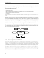
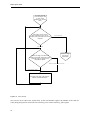
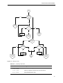
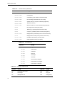
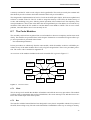
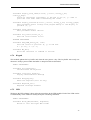
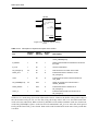
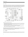
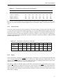
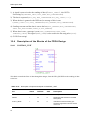
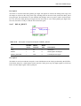
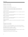
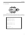
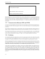
Figure 10–1: State diagram path for the Error case.
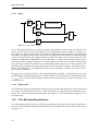
No Sending to Bus
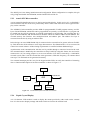
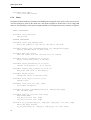
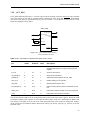
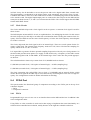
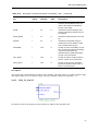
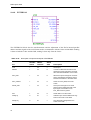
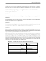
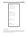
The pulse diagram is shown in Appendix N.6. Figure 10–2 shows the case where nothing is to be sent
as a reply.
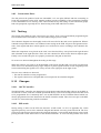
Figure 10–2: State diagram path for the no sending to the bus.
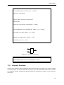
Sending to Bus
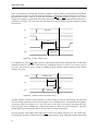
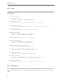
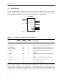
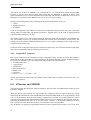
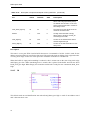
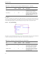
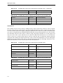
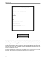
The pulse diagram is shown in Appendix N.7. Figure 10–3 shows the case where something is to be
sent as a reply.
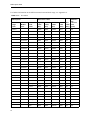
Figure 10–3: State diagram path for the sending to the bus.
108