1
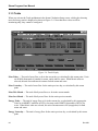
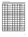
Form A6095 April 2002 Part Number D301145X012 STEAM/WATER THERMODYNAMICS APPLICATION PROGRAM User Manual Flow Computer Division Website: www.EmersonProcess.com/flow Steam Program User Manual Revision Tracking Sheet April 2002 This manual may be revised periodically to incorporate new or updated information. The revision date of each page is indicated at the bottom of the page opposite the page number. A significant change in the content of the manual also changes the date that appears on the front cover. Listed below is the revision date of each page. Page Revision All All ii, 12-17 9/00 9/01 4/02 Fisher, FloBoss and ROCLINK are marks owned by one of the Emerson Process Management companies. The Emerson logo is a trademark and service mark of Emerson Electric Co. Fisher Controls International, Inc. 2000-2002. All rights reserved. Printed in the U.S.A. While this information is presented in good faith and believed to be accurate, Fisher Controls does not guarantee satisfactory results from reliance upon such information. Nothing contained herein is to be construed as a warranty or guarantee, express or implied, regarding the performance, merchantability, fitness or any other matter with respect to the products, nor as a recommendation to use any product or process in conflict with any patent. Fisher Controls reserves the right, without notice, to alter or improve the designs or specifications of the products described herein. ii Rev 9/00 Steam Program User Manual Table of Contents SECTION 1 — INTRODUCTION..................................................................................1 1.1 Organization of Manual ............................................................................................................. 1 1.2 Overview Description ................................................................................................................ 2 1.2.1 Requirements...................................................................................................................... 2 1.3 Additional Information............................................................................................................... 3 1.4 Specifications ............................................................................................................................. 4 SECTION 2 DOWNLOADING THE STEAM PROGRAM.......................................7 2.1 2.2 2.3 2.4 Program Description .................................................................................................................. 7 Program Requirements............................................................................................................... 8 Viewing Available Memory....................................................................................................... 8 Download Procedure ................................................................................................................ 11 SECTION 3 — CONFIGURING THE STEAM PROGRAM................................... 13 3.1 Configuration ........................................................................................................................... 13 3.1.1 Inputs................................................................................................................................ 16 3.1.2 Alarms .............................................................................................................................. 19 3.1.3 Totals................................................................................................................................ 20 APPENDIX A — POINT TYPE LISTING ................................................................. 23 Rev 9/01 iii Steam Program User Manual [This page is intentionally left blank.] iv Rev 9/00 Steam Program User Manual SECTION 1 — INTRODUCTION The Steam/Water Thermodynamics Application Program (more briefly referred to as the Steam Program) is a user program that, when running in a ROC or FloBoss, performs calculations of mass and energy flow based on either volumetric flow, mass flow, or differential flow, static pressure, temperature, and steam quality inputs. Mass and energy flows are accumulated using daily and monthly totals; these values are stored in the ROC or FloBoss for later retrieval. 1.1 ORGANIZATION OF MANUAL This manual is organized into the following major sections: ♦ ♦ ♦ ♦ Section 1 Introduction Section 2 Downloading the Steam Program Section 3 Configuring the Steam Application Appendix A Point Type Listing Section 1 Introduction describes this manual and mentions related manuals. This section also provides an overview of the Steam Program. Section 2 Downloading the User Program describes how to view available memory, how to select a user program, and how to download the Steam Program to the ROC. Section 3 Configuring the Application provides information detailing how to configure the Steam/Water Application for a specific installation site. Appendix A Point Type Listing provides a breakdown of each parameter value set up in the User Data point type for the steam application. Rev 9/01 1 Steam Program User Manual 1.2 OVERVIEW DESCRIPTION The Steam/Water Thermodynamics Application Program provides energy calculations capability to ROC300-Series (models with FlashPAC only) and FloBoss 407 units. The software computes the “corrected” mass flow values and archives the data on hourly and daily cycles. ROCLINK Configuration Software for DOS is required to configure the calculations. ROCLINK also displays all pertinent data, including monthly mass and energy totals. The inputs to the system are the actual volumetric flow rate, provided by a vortex flowmeter or another linear meter, the process temperature, the process pressure, and the steam quality. As a second choice, a mass flow input (corrected) can be read directly from another device. The data from this input is archived for historical purposes just like an internally calculated mass flow. Using this program, the flow of water (chilled or hot), steam (saturated or superheated) and natural gas (orifice or turbine metered) may be measured concurrently in a ROC or FloBoss. Each flow measurement takes one of the meter runs available in the unit. The hourly and daily averages of the process temperature and pressure, plus the mass flow and energy flow rates are available to be archived on an hourly and daily basis. The maximum and minimum values for the day are recorded for each variable archived. The units of measurement can be configured to be either U.S. (a.k.a. English or Imperial) or metric for each steam calculation point. For further details, refer to the specifications in Section 1.4. For more information about downloading the program, refer to Section 2. For information on configuring the program, refer to Section 3. 1.2.1 Requirements To use the Steam Program, a ROC should have a FlashPAC installed, version 2.11 or greater. A FloBoss 407 should have firmware version 1.07 or greater. To be downloaded, the program requires available memory as described in Section 2. ROCLINK Configuration Software for DOS Version 2.23 is required for configuration. 2 Rev 9/01 Steam Program User Manual 1.3 ADDITIONAL INFORMATION This document is intended to be used along with the following manuals to assist in downloading and configuration. The physical (hardware) aspects of the ROC/FloBoss units are contained in their respective instruction manuals, as listed below. RL101 ROCLINK Configuration Software User Manual (Form A6051) – Part Number D301101X012 Type ROC306/312 Remote Operations Controller Instruction Manual (Form A4630) – Part Number D301059X012 Type ROC364 Remote Operations Controller Instruction Manual (Form A4193) – Part Number D301060X012 FloBoss 407 Flow Manager (Form A6013) – Part Number D301080X012 The steam and water properties calculation algorithms are contained in their respective standards, as listed below. ASME International SteamTables for Industrial Use, CRTD Vol.58, 1997 Rev 9/01 3 Steam Program User Manual 1.4 SPECIFICATIONS Many of the details of the Steam Program are summarized in the table below. Specifications MAXIMUM METER RUNS ROC306/ROC312: 3 runs ROC364: 5 runs ROC407: 4 runs COMMON FLOW PARAMETERS Tag ID: 10-character description. Meter Run ID: 30-character description of meter run. Calculation Method: International Association for the Properties of Water and Steam, International Formulation 1997 (IAPWS-IFC-97). Uses either US or metric units. Measurement Range: Pressure range is 0.1 - 2395 PSIA; temperature range is 32 - 662°F. Meter Configuration: Live reading or manual value: • Volumetric measurement from pulse, scaled analog, or Hart input. • Differential pressure from analog, or Hart input. • Pressure from analog or Hart input. • Temperature from analog or Hart input. • Mass flow (optional) from analog or Hart input. Steam Quality: Live reading or manual value: • Live reading may be from analog or Hart input. 4 • Manual (entered) value used in automatic override when temp/pressure is above or below the saturated steam region of the ASME Steam Table. CALCULATION OUTPUT Enthalpy: BTU/lbm (kJ/kg). Enthalpy Flow Rate (Energy): Instantaneous Flow, Flow per hour, Flow per day, Energy Today, Energy Yesterday, Energy This Month, Energy Last Month. Measured in MMBTU (MJ) for steam, or in MBTU (MJ) for water. Mass Flow Rate: Instantaneous, per hour, per day, Mass Today, Mass Yesterday, Mass This Month, Mass Last Month. Measured in MLb (tonnes) for steam, or in tons (tonnes) for water. 3 3 Density: lbm/ft (kg/m ). Max/Min: Available through history on daily basis. ALARMS Low/High Alarm: Limits beyond which an alarm will be indicated. RBX Alarm: Report-by-exception alarm call-in may be enabled. Rev 9/01 Steam Program User Manual Specifications (Continued) MONITORED VALUES Station Tag Atmospheric Pressure (Calc, Enter) Elevation Atmospheric Pressure (Calc, Enter) Low Alarm Limit High Alarm Limit Units (US English, Metric) Pressure (Absolute, Gauge) Alarm Mode Alarm Code Actual Volume Input or Actual Differential Pressure Pressure Input Temperature Input Quality Input Actual Volume Rate Pressure Temperature Coefficient of discharge (differential mode) Isentropic exponent (differential mode) Rev 9/01 Viscosity (differential mode) Expansion Factor (differential mode) Steam Quality Enthalpy Density Mass Flow per Hour Mass Flow per Day Mass Today Mass Yesterday Mass Current Month Mass Last Month Energy Flow per Hour Energy Flow per Day Energy Today Energy Yesterday Energy Current Month Energy Last Month 5 Steam Program User Manual 6 Rev 9/01 Steam Program User Manual SECTION 2 DOWNLOADING THE STEAM PROGRAM This section provides instructions for installing the Steam/Water Thermodynamics User Program into ROC or FloBoss memory. Be sure to read Section 2.2, Program Requirements, before proceeding to the actual program installation. This section includes: ♦ Program Description ♦ Program Requirements ♦ Viewing Available Memory ♦ Download Procedure NOTE:A PC-compatible computer must be connected to the Operator Interface port (LOI) before the downloading process is started. User program memory must be available (unallocated) in the intended download memory area. 2.1 PROGRAM DESCRIPTION When loaded into user program memory as instructed in Section 3, the Steam/Water Thermodynamics Application Program sets up points and parameters for the calculations. The ROCLINK Configuration Software is then used to configure and monitor each of these parameters. The program files are supplied either on a single 1.4 Mbyte diskette, or on a CD-ROM. Note that the steam parameters are referenced in the ROC/FloBoss the same as other point type parameters—by Type, Logical number, and Parameter (TLP). This allows parameters such as Static Pressure to be assigned as an input to a Process Variable for a PID loop, a variable to display on a Local Display Panel, or a variable for any other ROC function. Refer to Appendix A for a complete list of the parameters associated with the Steam point type. Rev 9/01 7 Steam Program User Manual 2.2 PROGRAM REQUIREMENTS The Steam/Water Thermodynamics Application Program is downloaded into and run from User Program memory located either in a FlashPAC module (ROC300-Series) or in a FloBoss 407. Requirements for the User Program: ♦ For ROC300-Series units, FlashPAC firmware version 2.11 or greater must be installed (check by using ROCLINK to look at the Advanced Features of the System Information display under the System menu). ♦ For FloBoss 407 units, firmware version 1.07 or greater must be installed (check by using ROCLINK to look at the Advanced Features of the System Information display under the System menu). ♦ ROCLINK Configuration Software Version 2.2 (check by using the About function in the Help menu of ROCLINK). Based on the available memory (see Section 2.3, Viewing Available Memory) or user task requirements, select one of the programs listed below. Fb_steam.h00 Code at memory block B8000 - BFFFF Data at memory block 70000 - 73FFF Runs out of User Task 3 Fp_steam.h00 Code at memory block D8000 - DFFFF Data at memory block B8000 - BBFFF Runs out of User Task 3 2.3 VIEWING AVAILABLE MEMORY User program memory must be available in the intended download area (see program requirements above) before installing a user program. To view the available memory: 1. Select Utilities from the ROCLINK menu bar. 2. Select User Programs. When you select User Programs, a screen appears that shows the unused memory blocks available for the Steam Program to be loaded. Refer to Figure 2-1. 8 Rev 9/01 Steam Program User Manual Figure 2-1. Viewing Memory in ROCLINK The memory location must be available for the User Program to be loaded. All unallocated (available) memory blocks display under this field. User programs cannot share the same memory block. Refer to the .h00 files listed in Section 2.2, Program Requirements, to determine which blocks of memory are required by the intended user program. The other fields on this screen are described below. User Program Name and Version — Displays the name of the User Program and the version number currently installed. Status — Displays the run status of the User Program: ON or OFF. Code — Code displays the location of where the program executable file resides in memory. Data — Data displays the location of where the program data files reside in memory. Download — When you select Download, the Open File (Figure 2-2) display appears for selecting the program files to be loaded. After you select a user program to install, you may press Enter or press Download again to begin loading the user program. Press More Files to select additional user programs for installation. More Files — After selecting a user program to download using the Open File display, you can press the More Files pushbutton to select additional user programs to download if desired. Rev 9/01 9 Steam Program User Manual Clear All — Press the Clear All pushbutton to clear all user programs stored in this ROC/FloBoss out of its memory. This is typically done if you need to load a user program into a memory block already in use. Turn On — To turn on a user program, select the check box next to the user program, and press the Turn On pushbutton. Note that the Status field displays ON or OFF to indicate the status of the user program. After turning on a user program, perform a Write to EEPROM or Write to Internal Config Memory procedure in the ROC Flags screen. This ensures that when a Cold Start is performed, the user program automatically starts. Turn Off — To turn off a user program, select the check box next to the user program, and press the Turn Off pushbutton. Note that the Status field displays ON or OFF to indicate the status of the user program. Cancel — Press the Cancel pushbutton to cancel all actions and leave the User Programs screen. 10 Rev 9/01 Steam Program User Manual 2.4 DOWNLOAD PROCEDURE Once you have determined the memory required by the desired user program is available (see Section 3.1), you may proceed to select and download the program. To download the Steam Program using ROCLINK: 1. Select Utilities from the ROCLINK menu bar. 2. Select User Programs. Refer to Figure 2-1 on page 9. 3. Press Download. The Open File dialog box appears as shown in Figure 2-2. The Open File display lists the names of all the files that have the .H00 extension and are located in the default Drive and Directory. Use the Up Arrow (↑) and the Down Arrow (↓) to select the desired file in the Files list. You may change the location being read by using the Directory/Drive field. . Use the Up Arrow (↑) and the Down Arrow (↓) to select the drive containing the user program files, such as the [-D] drive. 4. When the desired User Program appears in the File Name field, click OK. The Open File dialog closes, returning you to the User Program screen. Figure 2-2. Open File Rev 9/01 11 Steam Program User Manual 5. If you want to load other user programs as well, you may press the More File pushbutton to select them using the Open File dialog. To begin loading the selected User Program(s), press Download again. When the User Program has been downloaded, the following occurs: ♦ The User Program is automatically turned ON. ♦ The correct ROC Flag is automatically enabled for the User Program. ♦ A Warm Start is automatically initiated. ♦ A record is created in the Event Log if Log Data is enabled in the Config screen. ♦ The configurable data fields are located under the User Data menu. 6. After downloading the User Program, select Flags from the System menu to display the ROC Flags screen similar to the screen displayed in Figure 2-3. Figure 2-3. ROC Flags Display 7. Set the Write to EEPROM flag to Yes. This ensures that when a Cold Start is performed, the User Program automatically starts. 8. Press (F8)Save. 9. Press (F1)Update. 12 Rev 9/01 Steam Program User Manual SECTION 3 — CONFIGURING THE STEAM PROGRAM This section details how to configure steam flow points using the ROCLINK Configuration Software. Note that the flow points and their associated parameters will not be available in ROCLINK until the Steam/Water Thermodynamics User Program is downloaded as instructed in Section 2. For a detailed programmer’s listing of the parameters in a steam point, see Appendix A. 3.1 CONFIGURATION The Steam point type allows configuration of all parameters associated with the steam/water flow calculation, including inputs and alarms. Once the Steam Program is loaded into ROC/FloBoss memory and running, Steam Calculation screens become available from the ROCLINK menus. When you select the Steam option in the Meter menu, a screen similar to Figure 3-1 appears. Figure 3-1. Steam Calculation Setup Screen The Title Bar of the Steam Setup screen displays the specific number (such as 1 of 3) of the Steam Calculation point (also called a meter run) you are configuring. The number of Steam points available Rev 9/01 13 Steam Program User Manual varies from 3 in the ROC306/ROC312 to 5 in the ROC364. Press (F3)Next and (F2)Prev to view or configure other Steam Calculation points. Meter ID — Ten-character name (default is STEAM #1) for this meter run that resides in the ROC/FloBoss. This name can be changed by entering a new name in the field and pressing (F8)Save. Flow Input — Press the associated pushbutton to toggle between Volume (the default) and Mass. Unless you are connecting the ROC/FloBoss to a corrected mass flow input, leave Volume selected. Units — Press the associated pushbutton to toggle between U.S. (the default, also called English or Imperial) and Metric for this point. The input/output conversion calculations and units (as displayed on the screen) will automatically change to accommodate your selection. The units used or expected are summarized in the table below. Units of Measurement Summary Parameter Steam (U.S.) Steam (Metric) Water (U.S.) Water (Metric) MLbm/hr Tonnes/hr Tons/hr Tonnes/hr MMBTU/hr MJ/hr MBTU/hr MJ/hr Density Lbm/ft3 kg/m3 Lbm/ft3 kg/m3 Enthalpy BTU/Lbm KJ/kg BTU/Lbm KJ/kg Actual CF/hr Actual CM/hr Gal/min L/min Mass Flow Input MLbm/hr Tonnes/hr Tons/hr Tonnes/hr Static Pressure PSI kPa PSI kPa Temperature °F °C °F °C Steam Quality % % % % Alarm Limits MLbm/hr Tonnes/hr Tons/hr Tonnes/hr Mass Totals MLbm Tonnes Tons Tonnes MMBTU MJ MBTU MJ Mass Flow Rate Energy Flow Rate Actual Volume Flow Energy Totals Phase — Press the associated pushbutton to toggle between Steam (the default) and Water. Note that this selection changes only the units used (see the table above); it does not affect the calculation, which automatically changes based on the temperature and pressure (also see Steam Quality in Section 3.1.1). Mass Flow Rate — This parameter is a monitor-only field that displays the current calculated mass flow rate for this steam point. The value is recalculated once every second. 14 Rev 9/01 Steam Program User Manual Energy Flow Rate — This parameter is a monitor-only field that displays the current calculated energy flow rate for this steam point. The value is recalculated once every second. Density — This parameter is a monitor-only field that displays the density of the steam or water as calculated from the measured inputs. The value is recalculated every 5 minutes unless there is a significant change in one of the inputs. Enthalpy — This parameter is a monitor-only field that displays the enthalpy (energy content) of the steam or water as calculated from the measured inputs. The value is recalculated every 5 minutes unless there is a significant change in one of the inputs. Alarming — Select Enabled to allow alarms to be set up for this point. The Alarms pushbutton then becomes available; see Section 3.1.2 for further information. Static Press — Select either Absolute or Gauge, depending on the type of instrument being used to provide the pressure input for this point. Generally, an absolute measurement allows greater accuracy. If you select Gauge, then be sure also to specify Atmospheric Pressure and Elevation in the fields below. Atmospheric Press — If you selected Gauge pressure above, then select either Calculate or Enter. If you select Calculate, then also provide the Elevation of the meter location in the next parameter. If you select Enter, then the field immediately below becomes available for editing; otherwise it simply displays the calculated value. Type in the estimated average pressure. Elevation — If you selected Calculate for the Atmospheric Pressure, enter the elevation (in feet or meters) of the meter site in this field. The resulting atmospheric pressure is then displayed just below the Atmospheric Press selection and used by the steam point to calculate the Static Pressure in the case of gauge instruments. Active Alarms — This monitor-only field displays any alarms that are active for this steam point: Low, High, or No Flow. Inputs — Press this pushbutton to define the inputs for this steam flow calculation. See Section 3.1.1 for details. Alarms— If Alarming is Enabled, you can press this pushbutton to define the alarms for this steam flow calculation. See Section 3.1.2 for details. Totals — Press this pushbutton to display the flow totals for this steam flow calculation. See Section 3.1.3 for details. After configuring a point and pressing (F8)Save, use “Write to EEPROM” in the ROC Flags display to save the configuration to permanent memory in case you must perform a Cold Start. Rev 9/01 15 Steam Program User Manual 3.1.1 Inputs To define the inputs used in this steam flow calculation, press the Inputs pushbutton in the Steam Calculation Setup screen. This displays the Inputs dialog box shown in Figure 3-2. NOTE: Interpret the information on the I/O Definition pushbutton (for example, AIN A 3, EU) in the following manner. The first part is a three-character mnemonic (in this example, “AIN” means Analog Input) that indicates the Point Type. The second part (such as “A 3”) indicates the Point Number. The third part is a mnemonic indicating the selected Parameter (such as EU for the Filtered Engineering Units Parameter). Refer to Section 7 of the ROCLINK manual for a definition of mnemonics. NOTE: If you want to enter a constant value to be used as an input, type it in the Value field next to the I/O Definition pushbutton. You do not need to select the Manual point type before entering this value; the pushbutton will still read Undefined. For other point types, the field next to the pushbutton indicates the actual input value coming into the steam calculation. 16 Rev 9/01 Steam Program User Manual Figure 3-2. Inputs Definition Actual Volume Flow — If the Flow Input is set up as Volume in the Steam Setup screen, identify the input from a linear flowmeter, such as a vortex meter, that measures the volume of steam or water. If you want to enter a constant value to be used as the input, type the value in the Value field to the right of the pushbutton. Otherwise, this field just indicates the current input value. The units expected are actual cubic feet per hour for steam or in gallons per minute for water. If Metric is selected, then the units are actual cubic meters per hour for steam or liters per minute for water. Mass Flow — If the Flow Input is set up as Mass in the Steam Setup screen, use the associated pushbutton to identify the input providing a corrected mass flow (otherwise, leave this input undefined). If you want to enter a constant value to be used as the input, type the value in the Value field to the right of the pushbutton. Otherwise, this field just indicates the current input value. The units expected are MLbm/hr (thousand pounds per hour) for steam or tons per hour for water. If Metric units are selected, expected units are tonnes per hour for both steam and water. Static Pressure — The associated pushbutton displays a dialog box that lets you assign the input that senses the static pressure of the steam or water. If you want to enter a constant value to be used as the input, type the value in the Value field to the right of the pushbutton. Otherwise, this field just indicates the current input value. The units assumed for the input are PSI (kPa if Metric conversion is enabled). Be sure to Rev 9/01 17 Steam Program User Manual indicate the whether the pressure input is an Absolute or a Gauge measurement on the Steam Setup screen. Temperature — The associated pushbutton displays a dialog box that lets you assign the input that senses the temperature of the steam or water. If you want to enter a constant value to be used as the input, type the value in the Value field to the right of the pushbutton. Otherwise, this field just indicates the current input value. The units assumed for the input are degrees Fahrenheit (degrees Celsius if Metric units are enabled). Steam Quality — The associated pushbutton displays a dialog box that lets you assign the input that indicates the quality of the steam for supersaturated steam. If you want to enter a constant value to be used as the input, type the value in the Value field to the right of the pushbutton. Otherwise, this field just indicates the current input value. The units assumed for the input are always percent of steam. Note that if the pressure and temperature are in the superheated steam region, the Steam Quality will be forced to 100%. If the pressure and temperature are in the water region, this value will be forced to 0%. 18 Rev 9/01 Steam Program User Manual 3.1.2 Alarms If you have Alarming enabled for this Steam flow point, press the Alarms pushbutton in the Setup screen to display the dialog box shown in Figure 3-3. Figure 3-3. Alarms Definition Low Alarm Limit — The limit value (default is 0), in engineering units per hour, to which the calculated mass flow value must fall to generate a Low Alarm. High Alarm Limit — The limit value (default is 10,000), in engineering units per hour, to which the calculated mass flow value must rise to generate a High Alarm. RBX Alarming —Select the type of RBX (automatic call-in to host) alarming you want for this alarm: Disabled, On Alarm Set, On Alarm Clear, or On Alarm Set & Clear. For RBX alarming to function, you must also set up the RBX features as described in Section 9 of the ROCLINK user manual. Rev 9/01 19 Steam Program User Manual 3.1.3 Totals When you activate the Totals pushbutton in the Steam Calculation Setup screen, a dialog box showing mass and energy totals is displayed as shown in Figure 3-4. Note that these values are all for monitoring only; they cannot be configured. Figure 3-4. Totals Display Mass Today — The total of mass flow so far in the current day, as calculated by this steam point. Units are in MLb (thousands of pounds) for steam, and in tons for water. When Metric units are selected, the unit of measurement is tonnes for both steam and water. Mass Yesterday — The total of mass flow for the entire previous day, as calculated by this steam point. Mass This Month — The total of daily mass flows so far in the current month. Mass Last Month — The total of daily mass flows for the entire previous month. Energy Today — The total of energy flow so far in the current day, as calculated by this steam point. Units are in MMBTU (millions of BTUs) for steam, and in MBTU (thousands of BTUs) for water. When Metric units are selected, the unit of measurement is MJ (megajoules) for both steam and water. Energy Yesterday — The total of energy flow for the entire previous day, as calculated by this steam point. 20 Rev 9/01 Steam Program User Manual Energy This Month — The total of daily energy flows so far in the current month. Energy Last Month — The total of daily energy flows for the entire previous month. Rev 9/01 21 Steam Program User Manual 22 Rev 9/01 Steam Program User Manual APPENDIX A — POINT TYPE LISTING Table A-1 shows the parameter definitions for the Steam point type, which is a User Data point tailored for the Steam/Water Thermodynamics application. For further descriptions of the parameters used in configuring the ROC/FloBoss, refer to Section 3 of this manual. Table A-1. Point Type 27, Steam Flow Parameters PARAM NUMBER READ/ WRITE VALID RANGE DATA TYPE LENGTH DEFAULT VALUE DESCRIPTION (UNITS FOR STEAM) 0 R/W Printable ASCII characters, 0x20->0x7d AC 10 STEAM #x, where x = 1+ logical number Point Tag Id. 1 R/W 0->1 UC 1 0 Flow Input (0=Volume, 1=Mass, 2=Orif flange, 6=Orif DD2, 10=Orif Corner, 14=Nozzle, 18=Vent Mach, 22=Vent RW) 2 R/W 0->1 UC 1 0 Units Option (0=U.S., 1=Metric) 3 R/W 0->1 UC 1 0 Phase (0=Steam, 1=Water) 4 R/W 0->1 BIN 1 0 Pressure Option Bit 0= 0 - Absolute Bit 0= 1- Gauge Bit 1=0 – Upstream Bit 1=1 –Downstrm 5 R/W 0->1 UC 1 0 Atmospheric Pressure Option (0=Calculate, 1=Enter) 6 R/W 0->0xff BIN 1 0 Alarming Mode Bit 6–SRBXonSet Bit 5-SRBXonClear Bit4-ALMEnable 7 Rev 9/01 R/O 0->0xff BIN 1 0 Alarm Code Bit 6-NoFlowAlarm Bit 2-HighAlarm Bit 0-LowAlarm 23 Steam Program User Manual PARAM NUMBER READ/ WRITE VALID RANGE DATA TYPE LENGTH DEFAULT VALUE DESCRIPTION (UNITS FOR STEAM) 8 R/W 0->1 UC 1 0 Steam Properties Recalculation Flag (1=Recalc) 9 R/W 0,0,0 or 3,x,14 or 5,x,13 or 5,x,17 or 16,x,2-11 or 17,x,2-21 or 31,x,11 or 31,x,15 or 31,x,17 or 31,x,19 where x is a valid point number for the given point type TLP 3 0,0,0 Actual Meter Input Point (Volume Rate, Corrected Mass rate or Differential pressure) 10 R/W Valid IEEE Floating Point Number FLP 4 0 Actual Meter Value (ACFH or ACMH for Linear Meters, In Water at 68F or kPa for Differential press ) 11 R/W 0,0,0, or 3,x,14 or 16,x,2-11 or 17,x,2-21 or 31,x,11 or 31,x,15 or 31,x,17 or 31,x,19 where x is a valid point number for the given point type TLP 3 0,0,0 Pressure Input Point 12 R/W Valid IEEE Floating Point Number FLP 4 0 Pressure Value (PSI or kPa) 13 R/W 0,0,0, or 3,x,14 or 16,x,2-11 or 17,x,2-21 or 31,x,11 or 31,x,15 or 31,x,17 or 31,x,19 where x is a valid point number for the given point type TLP 3 0,0,0 Temperature Input Point 14 R/W Valid IEEE Floating Point Number FLP 4 0 Temperature Value (°F or °C) 15 R/W 0,0,0, or 3,x,14 or 16,x,2-11 or 17,x,2-21 or 31,x,11 or 31,x,15 or 31,x,17 or 31,x,19 where x is a valid point number for the given point type TLP 3 0,0,0 Steam Quality Input Point 16 R/W 0-100 FLP 4 100 Steam Quality Value (%) 24 Rev 9/01 Steam Program User Manual PARAM NUMBER READ/ WRITE VALID RANGE DATA TYPE LENGTH DEFAULT VALUE DESCRIPTION (UNITS FOR STEAM) 17 R/W 0,0,0, or 3,x,14 or 16,x,2-11 or 17,x,2-21 or 31,x,11 or 31,x,15 or 31,x,17 or 31,x,19 where x is a valid point number for the given point type TLP 3 0,0,0 Mass Flow Input Point 18 R/W Valid IEEE Floating Point Number FLP 4 500 Elevation (Feet or Meters) 19 R/W Valid IEEE Floating Point Number FLP 4 14.467 Atmospheric Pressure (PSI or kPa) 20 R/W Valid IEEE Floating Point Number FLP 4 0 Low Flow Alarm Limit (MLbm/hr or tonnes/hr) 21 R/W Valid IEEE Floating Point Number FLP 4 10,000 High Flow Alarm Limit (MLbm/hr or tonnes/hour) 22 R/W Valid IEEE Floating Point Number FLP 4 8 Pipe Diameter (inches or mm) 23 R/W Valid IEEE Floating Point Number FLP 4 4 Orifice Diameter (inches or mm) 24 R/W Valid IEEE Floating Point Number UC 4 0 Pipe Material Code Valid IEEE Floating Point Number UC 25 R/W (0 to 12) 4 0 Orifice Material Code (0 to 12) 26 R/W Valid IEEE Floating Point Number FLP 4 68 Pipe Measuring Temperature (°F or °C) 27 R/W Valid IEEE Floating Point Number FLP 4 68 Orifice Measuring Temperature (°F or °C) 28 R/O Valid IEEE Floating Point Number FLP 4 0 Steam Enthalpy (BTU/lbm or kJ/kg) 29 R/O Valid IEEE Floating Point Number FLP 4 0 Steam Density (lbm/ft3 or kg/m3) 30 R/O Valid IEEE Floating Point Number FLP 4 0 Mass Flow Rate / Hour (MLbm/hr or tonnes/hr) Rev 9/01 25 Steam Program User Manual PARAM NUMBER READ/ WRITE VALID RANGE DATA TYPE LENGTH DEFAULT VALUE DESCRIPTION (UNITS FOR STEAM) 31 R/O Valid IEEE Floating Point Number FLP 4 0 Mass Flow Rate / Day (MLbm/day or tonnes/day) 32 R/O Valid IEEE Floating Point Number FLP 4 0 Energy Flow Rate / Hour (MMBTU/hr or MJ/hour) 33 R/O Valid IEEE Floating Point Number FLP 4 0 Energy Flow Rate / Day (MMBTU/day or MJ/day) 34 R/O Valid IEEE Floating Point Number FLP 4 0 Mass Flow Today (MLbm or tonnes) 35 R/O Valid IEEE Floating Point Number FLP 4 0 Mass Flow Yesterday (MLbm or tonnes) 36 R/O Valid IEEE Floating Point Number FLP 4 0 Energy Flow Today (MMBTU or MJ) 37 R/O Valid IEEE Floating Point Number FLP 4 0 Energy Flow Yesterday (MMBTU or MJ) 38 R/O Valid IEEE Floating Point Number FLP 4 0 Mass Flow This Month (MLbm or tonnes) 39 R/O Valid IEEE Floating Point Number FLP 4 0 Mass Flow Last Month (MLbm or tonnes) 40 R/O Valid IEEE Floating Point Number FLP 4 0 Energy Flow This Month (MMBTU or MJ) 41 R/O Valid IEEE Floating Point Number FLP 4 0 Energy Flow Last Month (MMBTU or MJ) 42 R/O Valid IEEE Floating Point Number FLP 4 1.0 Coefficient of discharge 43 R/O Valid IEEE Floating Point Number FLP 4 0.1 Viscosity (cP) 44 R/O Valid IEEE Floating Point Number FLP 4 1.2 Isentropic exponent 45 R/O Valid IEEE Floating Point Number FLP 4 1.0 Expansion factor 26 Rev 9/01 Steam Program User Manual Rev 9/01 27 Steam Program User Manual If you have comments or questions regarding this manual, please direct them to your local sales representative or contact: Emerson Process Management Flow Computer Division Marshalltown, IA 50158 U.S.A. Houston, TX 77065 U.S.A. Pickering, North Yorkshire UK Y018 7JA Website: www.EmersonProcess.com/flow 28 Rev 9/01