1
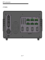
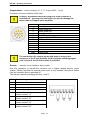
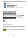
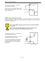
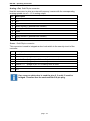
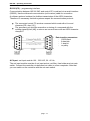
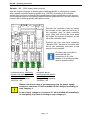
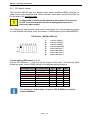
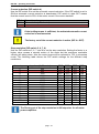
iMC-S8 – operating instruction Use external emergency stop: pin 5 and 6 bridged pin 7 and 8 bridged The length of the connection cable for the external emergency stop button must not more than 5m. Use external power button: pin 1 and 2 bridged connect external power button (make contact) on pin 3 and 4 Impulse - interface impulse control, 8-pin connector Use this connector to integrate the function keys start button, stop button and reset from the controller front side as external signal inputs. pin 1 2 3 4 5 6 7 8 description input external START button +24VDC input external STOP button output lamp START button GND output lamp STOP button input length measure switch +24VDC If the external STOP button is not used pins 2 and 3 must be bridged. Input - digital inputs, 8-pin connector The controller has 8 digital user inputs. Use these inputs to connect external devices like sensors, switches or outputs from other devices. All inputs are opto-decoupled. If +24VDC lies on the input a logical HIGH is signalized. Not connected (e.g. switch open) a logical LOW is signalized. Do not short 24VDC reference potential of the controller with GND or case ground. page - 14