1
RSI TOW CONVEYOR
PREVENTIVE MAINTENANCE & TROUBLE SHOOTING MANUAL
1.
2.
3.
INTRODUCTION
A. System Summary -------------------------
2
System Start-up Procedure----------------------Preventive Maintenance -------------------------
2
3-9
A.
B.
C.
D.
E.
F.
G.
H.
I.
J.
3.2.
Motor
Gear Reducer (Fig 3)
Pusher (Fig 1)
Drive Roller Chain (Fig 2)
Drive Belt (Fig 3,4)
Drive Belt Pulley (Fig 4)
Sprockets
Idler Pulleys (Fig 7)
Flange Bearings (Fig 8)
Take-up Roller (Fig 9)
Tow Chain and Track --------------------------A.
A1.
A2.
A3.
B.
C.
D.
9-13
Tow Chain
Tow Chain Adjustment (Fig 5)
Take-up Rod Adjustment (Fig 10)
Automatic Oiler
Horizontal Curve (on-floor)
Straight (on-floor & in-floor)
Horizontal Curve
3.3.
Tow Carts (Fig 15----------------------------A.
Tow Pin & Pin Tube (Fig 15)
13-15
4.1.
Trouble Shooting ------------------------------
16-18
A.
B.
C.
D.
E.
Drive (Fig 16&17)--------------------Drive Diagnostic Procedures ---------Tow Chain
Carts Not Releasing
Chain Oiler (Fig 19)
16
21-27
4.2
4.3
4.4
Pneumatics (Delay Stations Fig 20) --------- 18-19
Electrical (Delay Stations Fig 21) ----------19
Speed Reducer ----------------------------- 21-26
5
Electrical Safety And This Control Panel ----27-42
6
Spare Parts / Parts Drawings-----------------43-53
Maintenance records--------------------------55-56
1
RSI TOW CONVEYOR SYSTEM
1.
INTRODUCTION
This manual has been designed to help you achieve many years of
trouble free low maintenance production from your RSI Tow Conveyor System.
Only the finest material and components have been chosen in the
manufacturing of this system and we here at RSI, Inc. recommend that only
the finest lubricants and RSI, Inc. approved maintenance procedures be used
in the systems regular scheduled maintenance program. We feel confident
that if these procedures are followed you will receive many years of
trouble free service from your system.
A.
SYSTEM SUMMARY
The RSI Tow Conveyor System has been designed to adapt to most of your
manufacturing needs, from furniture manufacturing and finishing to marine
and automotive engines to almost anything produced on the factory assembly
line.
The versatility of the Tow Conveyor is achieved by the use of a
special tow chain which allows the carts to be placed on practically any
center distance you choose. This combined with adjustable speed ranging
from 8 FPM to 12 FPM allow for the right amount of time for each operation
to be completed properly, and not the hurry-up, here-comes-the-next-part
method that can cause costly mistakes and poor overall quality. These
features are incorporated with cart delays which can be placed in work
stations, spray booths, drying ovens or practically anywhere on the system
as required by your particular needs.
2.
START - UP PROCEDURE (AFTER MAIN SHUT DOWN)
A.
B.
C.
D.
E.
F.
Visually inspect entire length of conveyor to
ensure there are no objects in or on top of chain or track.
Visually inspect all cart delays to ensure all
stops are in position.*
Visually inspect drive unit for objects in or
around the drive gears and check Tow Chain for slack.
Fill automatic oiler if necessary.
All workstations should be attended.
Turn on main power switch.
WARNING: Carts should be in proper rotation for manufacturing sequence.
WARNING: Before performing maintenance, air & electricial should be
turned off unless specified elsewhere in this manual.
2
3. PREVENTIVE MAINTENANCE
A. MOTOR:
The Reliance 2 hp/3 ph explosion proof A.C. motor is a sealed
self-lubricating unit, keep unit clean at cooling fins and fan to
allow motor to obtain adequate ventilation.
B. GEAR REDUCER:
Grove Gear Flex - A - Line #1425
This unit is completely adjusted and lubricated from the factory.
Gearbox oil should be changed every six (6) months or 2500
operating hours. Oil change intervals should be increased to
four (4) months or 1650 operating hours when total cart weight
(cart & product) exceeds 1000 lbs. This interval (4/1650)
should be used if the environment is dusty or excessive humidity
is present.
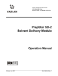
C. PUSHER:
A:
B:
C:
D:
E:
PUSHER CYLINDER
LIMIT SWITCHES
LIMIT SWITCH Wands
PUSHER BLOCK ASSEMBLY
PILOT VALVE
Figure # 1
Pusher should be adjusted so that a cart transfers over
the dead space in the drive at the same speed as the towline
chain is running. If this cannot be achieved, perform the
following procedures:
1.
2.
3.
4.
Check
Check
Check
Check
airlines for foreign material
limit switch and pilot valve for foreign material.
pusher block assembly for obstacles.
and adjust flow controls as needed.
Warning: Have the air disconnected before performing this operation
3
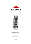
D. DRIVE ROLLER CHAIN: (see Fig #2)
A: RMI 084-1017 DRIVE ROLLER CHAIN
B: RMI 531-1002 GEAR REDUCER
Figure # 2
Chain tension should be adjusted when lateral movement
exceeds 1/4". To achieve proper chain tension the
following steps should be followed:
WARNING: Before performing any maintenance, electricial should be
turned off and disconnected.
1. Loosen four (4) bolts on underside of speed
reducer. (see Fig #3)
2. Loosen lock nuts on adjusting screws located on
pusher side of speed reducer. (See Fig #3)
3. Turn adjustment screws clockwise to achieve
proper chain tension. *
* Care should be taken to ensure adjustment screws are
turned the same number of turns to keep speed reducer
shaft and motor shaft parallel.
4. Once proper tension is achieved retighten lock nuts on
adjustment screws then retighten bolts on underside of
speed reducer.
4
A: MOUNTING BOLTS
B: GEAR REDUCER
C: ADJUSTING SCREWS
Figure # 3
A: SHEAVES
B: STRAIGHT EDGE
Figure # 4
5. Check V-Belt pulleys for proper alignment.
If pulleys are in excess of 1/4" out of alignment adjust
pulley position on motor and/or speed reducer shaft to
achieve proper alignment. (See Fig #4)
NOTE: If adjustment screws are at their Maximum
mechanical allowance (approx. 3/4 movement) Drive
Roller Chain must be removed and one link removed
and reinstalled to achieve proper tension.
WARNING: Before performing any maintenance, electricial should be
turned off and disconnected.
6. Lubrication of drive roller chain should be performed as
follows:
Clean environment:
(REF. sec. 3.1-C)
Food grade lubricants only!
Every 150 operating hours.
Moderate environment:
(REF. sec. 3.1-C)
Texas Co. Meropa oil type #1 or equal
(Call RSI, Inc. for equals)
Dirty
(REF.
Texas
(Call
environment:
sec. 3.1-C)
Co. Meropa oil type #1 or equal
RSI, Inc. for equals)
5
E. DRIVE BELT: (see Fig # 4,5)
A:
B:
C:
D:
E:
MOTOR MOUNTING BOLTS
ADJUSTMENT SCREW
SET SCREW
1-1/4” ADJUSTING NUT
TAKE-UP ARM ASSEMBLY
FIGURE # 5
WARNING: Before performing any maintenance, electricial should be
turned off and disconnected.
Drive belt tension should be adjusted when lateral movement
exceeds 1/2". To ensure maximum life from the drive belts they
should be treated every 6 mos. or 2500 operating hours with a
high grade automotive belt dressing. To acquire proper belt
tension the following steps should be followed.
1. Loosen four (4) nuts on motor base.
2. Turn adjustment screw on motor mount clock
wise until proper belt tension is
acquired.
3. Retighten four (4) nuts on motor base.
F. DRIVE BELT PULLEY: (see Fig #5)
Inspect all screws for tightness every 6 mos. or 2500
operating hours. No other maintenance or lubrication will be
required under normal operating conditions.
6
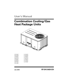
G. SPROCKETS (MAIN DRIVE): (see Fig #6)
Periodically inspect for excessive tooth wear or missing teeth.
Replace if teeth are missing or showing excessive wear. No other
maintenance or lubrication will be required under normal
operating conditions.
A: RMI 521-1010
B: RMI 521-1046
PRIMARY DRIVE SPROCKET
SECONDARY DRIVE SPROCKET
FIGURE # 6
H. BREAK-OVER ROLLERS {ENTRY & EXIT}: (see Fig #7)
Periodically inspect pulleys for excessive wear (mushrooming) on
surface (Tow Chain Side) if excessive wear is observed replace
pulley. If excessive movement on shaft (1/4" plus) is present
replace roller. No other maintenance or lubrication
will be required under normal operating conditions.
WARNING: Before performing any maintenance, electricial should be
turned off and disconnected.
7
A: DRIVE BREAK OVER ROLLERS
{Entry: RMI 089-1040---hardened roller}
{Exit: RMI 089-1440---standard roller}
FIGURE # 7
I. FLANGE BEARING: (see Fig #8)
On a standard drive unit there are ten (10) flange bearings
these flange bearing are sealed units and should be lubricated
with Standard Oil grease or equal (Call RSI, Inc. for equals)
every 150 operating hours.
A: RMI 031-1011 FLANGE BEARINGS {10}
B: LUBRICATION POINTS
FIGURE # 8
8
J. IDLER PULLEY: (see Fig #9)
Periodically inspect surface (Tow Chain Side) for excessive wear
(mushrooming). If excessive wear is present replace Idler
Pulley. If excessive movement on shaft (1/4" plus) is present
replace Garlock Bushing.
WARNING: Before performing any maintenance, electricial should be
turned off and disconnected.
A: RMI-089-1041 IDLER ROLLER
FIGURE # 9
3.2 TOW CHAIN AND TRACK:
A. TOW CHAIN:
Visually inspect tow chain for proper lubrication (lack
of oil excessive oil) Visually inspect Tow Chain at drive unit
for proper tension.
NOTE: Tow Chain may or may not have lateral movement when drive
is disengaged. When drive is engaged chain will show up to
3" of lateral movement.
WARNING: Do not work on chain while system is in motion.
HELPFUL HINT:
If chain is to loose the system will surge (run erratically)
as so if chain is too tight system will also surge.
Experiment with chain tension to achieve smooth operation of
your system to suit your application.
Lubrication of Tow Chain is provided by a drip oiler located in the
drive unit. Keep oiler filled with SAE 30W oil. Check oil level daily.
9
A1. To adjust Tow Chain Tension the following steps should be
followed: (see Fig #5)
1. Loosen set screw at drive end of take up rod. Turn
1-1/4" nut counter clock wise to achieve proper chain
tension
(See Helpful Hint At Sec. 3.2 A)
2. Retighten setscrew.
A:
B:
C:
D:
E:
8” TAKE-UP ROLLER
TAKE-UP ROD
TAKE-UP SWING ARM
SET SCREW
7/8” NUT
FIGURE 10
A2. When take-up rod has been adjusted to its maximum mechanical
allowances it will be necessary to remove links from the
Tow chain.
To remove links from the Tow Chain the following steps
should be followed:
With master link at drive unit: (see Fig #11)
1. Loosen setscrew at drive end of take-up rod. Turn
1-1/4" Nut (Fig #5) clockwise until 8" Idler
Pulley is within 1" from main drive gear.
(Fig #10)
2. Manually (BY HAND) turn Drive Pulley until all towchain slack can be pulled up through the
exit end of the drive unit. (Fig #12 & Fig #13)
3. Remove master link and overlap excess chain (See
Fig #12) where overlap meets point of master link
10
connect, cut tow chain with bolt cutter and discard
excess chain.
4. Reconnect Tow-Chain by replacing master link (CAUTION: Master
link to be installed in the vertical position. See Fig #11)
Care should be taken to assure tow-chain is not twisted.
5. Adjust tow-chain as described in Sec. 3.2 - A1.
A: RMI 768-1100 MASTERLINK
B: RMI 531-1225 DRIVE MOTOR
FIGURE # 11
11
A: V- BELTS
B: GEAR REDUCER
FIGURE # 12
A: RMI 768-1026 RSITOW CHAIN
B: RMI 768-1100 RSIMAASTERLINK
FIGURE # 13
A3.
Automatic Chain Oiling System Check oil level in reservoir every 24
operating hours and top off as required. (Rec. Lubricant RMI-1130 MPO30).
1. INJECTORS:
Check each injector for proper operation. After checking for
operation adjust injectors for required lubrication.
NOTE: If your system is equipped with a Lubecon Automatic Oiler. See
12
manual supplied by Lubecon Inc.
B. HORIZONTAL CURVE: (ON-FLOOR)
The curves on on-floor systems are equipped with UHMW. The UHMW
(white plastic) should be visually inspected periodically and
replaced if damaged or worn to the extent that the Tow-Chain is
not held in place properly. No other maintenance or lubrication
will be required under normal operating conditions.
C. STRAIGHT TRACK:
Visually inspect all tracks for obstructions or damage daily. (Both
ON-FLOOR and IN-FLOOR systems) Check bolts on on-floor track for
tightness every 2500 operating hours.
D. HORIZONTAL CURVE: (IN-FLOOR)
Periodically inspect UHMW (White Plastic) for damage and excessive
wear (REF. 3.2-B). No other maintenance or lubrication will be
required under normal operating conditions.
3.3 TOW CARTS:
All Tow Carts should be periodically visually inspected for damage to
stop bar. Flap hinge, pin and pin tube. Lubrication of Tow Cart
components will be as follows:
MED. DUTY CASTER SWIVEL BEARING:
Lubricate thru cup hole as follows:
Clean environment: (REF 3.1 - C) Texaco Regal Oil
F (R & D) Temp. rating 150°- 500° F or equal
(Call RSI, Inc. for equals)
every 150
operating hours.
MODERATE ENVIRONMENT:
(REF 3.1 - C) Every 50 operating hours.
DIRTY ENVIRONMENT:
(REF 3.1 - C) Every 20 operating hours.
HEAVY DUTY CASTER SWIVEL BEARING: (see Fig #14)
Lubricate thru Lube Zerk as follows:
CLEAN ENVIRONMENT: (REF page 3 - C) Texaco thermatex
Ed-1 temp. rating 350° - 500° F or Texaco low temp. 57 temp
rating -40° - 350° F or equal (Call RSI, Inc. for equals)
Every 150 operating hours.
MODERATE ENVIRONMENT: (REF page 3 - C) every 50 operating
hours.
DIRTY ENVIRONMENT: (REF page 3 - C) Every 20 operating
hours.
13
MED. AND HEAVY DUTY WHEEL BEARINGS: (see Fig #14)
Lubricate thru Lube Zerk as follows:
CLEAN ENVIRONMENT: (REF page 3 - C) Texaco Thermatex
ED - 1 Temp. Rating 350° - 500° F or Texaco low Temp. 57 Temp.
Rating -40° - 350° F or equal (Call RSI, Inc. for Equal)
Every 150 operating hours.
MODERATE ENVIRONMENT: (REF page 3 - C) Every 50 operating
hours.
DIRTY ENVIRONMENT: (REF page 3 - C) Every 20 operating hours.
A. CART ASSEMBLY: (see Fig #15)
Tow pin engagement should be checked for point wear.
Periodically remove Pin and hone tube with carbon brush.
Lubricate pin and tube with State TEF Dry Lube or equal (Call
RSI, Inc. for equal) as follows:
CLEAN ENVIRONMENT: (REF 3.1 - C) Every 100 operating
hours.
MODERATE ENVIRONMENT: (REF 3.1 - C) Every 50 operating
hours.
DIRTY ENVIRONMENT: (REF 3.1 - C) Every 20 operating
hours.
14
A: CASTER
B: LUBE FITTING
FIGURE # 14
A:
B:
C:
D:
E:
PIVOT AXLE
PRIMARY FLAPPER
½” BOLT FOR PRIMARY FLAPPER
PIN TUBE
SECONDARY LIFT HINGE
FIGURE # 15
15
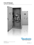
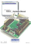
A: INPUT FUSES
A1: DISCONNECT HANDLE
B: INVERTER
C: AIR PRESSURE SWITCH
D: 5% FIELD CHOKE
E: LOGIC RELAY
F: MAIN FUSES
G: TOUCH SCREEN
FIGURE # 16 & 17
4.1 TROUBLE SHOOTING:
A: DRIVE: (see Fig #17, part B)
The RSI Tow Chain Conveyor is equipped with an Danfoss series
2800 Adjustable Frequency A.C.Drive. This unit has an on board computer
that will greatly reduce the time spent on trouble shooting the drive unit.
The Danfoss series 2800 is equipped with a local display that will display
fault codes. You will find a label on the panel that lists these fault
codes for your convenience. These codes are listed in the user manual
supplied with all inverters and or control panels.
B. After making adjustments and corrections found in fault codes and
diagnostic procedures by symptom sheet. Refer to the Danfoss series 2800
Trouble Shooting Guide.
16
C. TOW CHAIN JUMPS TEETH ON MAIN DRIVE GEAR:
Check position of chain guide. If chain guide is adjusted to its
maximum mechanical allowance. Replace UHMW insert.
A: CHAIN GUIDE
B: UHMW INSERTS
FIGURE # 18
D. DRIVE RUNS BUT CARTS WILL NOT RELEASE:
Check counter sprocket and/or Proximity Switch:
(CART VALUE, AVG. CART VALUE OR CART ON CALL SYSTEM)
17
A: PETCOCK W/ SIGHT GLASS
B: RESERVOIR
C: BRUSH
FIGURE # 19
E. SYSTEM HAS OIL PUDDLES AT TURNS:
Check oiler at drive unit(s) for excessive flow, and adjust to
approx. 3 drops every min. Gauge through view window. (Fig # 19)
4.2 PNEUMATICS:
Check operation of Air pressure switch first!
Stops not operating properly:
Check for moisture in airlines or compressor.
Check for debris in valves.
Check sequence of limit valves.
Cylinder respond time slows or stops:
Check exhaust mufflers for clogging (Fig. 20).
Check for moisture in airlines.
18
A:
B:
C:
D:
STOP UNIT
PILOT VALVE
ELECTRIC LIMIT SWITCH
EXHAUST MUFFLERS
A: LIMIT WAND
B: ELECTRIC LIMIT SWITCH
C: ELECTRIC SOLENOID
FIGURE # 20
Figure # 21
4.3 ELECTRICAL:
Check operation of air pressure switch first!
Stops not operating properly
Check roller arm to assure proper position on limit switch. Once
roller arm is in position tighten nut to hold roller arm in proper
position. (See Fig #21)
Check limit switch head for loose screws and/or damage. If limit
switches pass visual inspections as listed above and indicator on P.C.
board illuminates when limit switch is activated then move on to check
electric solenoid valve on station(s) that aren't operating properly.
To check solenoid valve push override on solenoid if valve is
operating properly the stop will drop down to release cart. If not the
valve may need cleaning or moisture in the air.
Check for loose connection on limit switch and at junction box.
19
WARNING: BEFORE PERFORMING ANY TYPE OF WORK ON THIS SYSTEM, HAVE
THE ELECTRICAL AND AIR TURNED OFF AND LOCKED OUT. UNLESS
IT IS OTHERWISE STATED IN THIS MANUAL.
WARNING: A QUALIFIED PERSON SHOULD ONLY DO WORK PERFORMED ON THIS
SYSTEM.
WARNING: DO NOT MANUALLY ENGAGE OR DISENGAGE CART ON THE CONVEYOR
WHILE IT IS IN OPERATION.
WARNING: KEEP ALL PARTS OF THE ANOTOMY CLEAR OF ANY MOVING PARTS
ON THIS SYSTEM.
20
21
22
23
24
25
26
Electrical Safety and
This Control Panel
27
ELECTRICAL SAFETY CONSIDERATIONS
NEVER WORK ALONE ON ELECTRICAL EQUIPMENT. YOU SHOULD ALWAYS HAVE A
SAFETY PERSON WATCHING YOU WORK. This person should know CPR and emergency
response regarding electrocution.
Only qualified personnel should do electrical service work.
Always wear cotton work cloths. Never wear polyester work uniforms as they will stick to your
skin when they catch fire and make the burns you receive much worse than they normally
would have been.
Never assume that the equipment being serviced is shut down unless you personally have
seen the disconnect pulled, locked out with your equipment, and tagged.
Never open a control or work on an electrical device with the power on unless you are fully
qualified to do so.
Follow prescribed lock out procedures prior to starting any service on electrical equipment.
There should be 72" of free space in front of any electrical panel.
Isolation mats should be placed in front of electrical panels.
A safety disconnect switch should be with in 30 feet of, or in sight of, any electric motor.
Never change fuses with the power on. Use only approved fuse pulling pliers. Slip joint pliers,
like $Channel Locks# are for pipe, they will bite you when used as a fuse puller.
Remember that even small signals can be lethal. It is possible to be electrocuted by a 9 volt
battery under the right conditions.
Shielded wires are especially dangerous. The shield can self pump to several thousand volts
when improperly handled. Prior to working on any shielded wire for any reason, clip the shield
to a known ground.
Conductors feeding high impedance devices can have ultra-high voltage levels on them. Treat these
wires with a great deal of respect since they can be instantly
28
If you are qualified to work on an open control panel and circumstances require that the power be on;
then treat every conductor as if it had lethal voltages present, be aware of grounding, use only double
insulated tools, and follow $hot panel# protocols.
When initiating power flow to an open panel, always turn your head away from the enclosure
and close your eyes, when closing the switch.
If you should happen to contact a live wire and receive a shock, seek medical advise on the
proper course of action to take regarding your future health. In some cases, admittance to a
hospital for observation may be required for one or more days as heart and nerve problems
associated with electrical contact can take time to manifest themselves.
If working with DC or synchronous motors, always put a shunt bar across the motor leads. If
the motor shaft is turned while you are working on the equipment, the motor will become a
generator and can electrocute you.
If working on equipment with current transformer(s) (CT
encounters.
s or doughnuts), shunt the leads to prevent high voltage
29
ATTENTION:
Servicing energized Industrial Control Equipment can be hazardous.
Severe injury or death can result from electrical shock, burn, or unintended actuation of controlled equipment.
Recommended practice is to disconnect and lockout control equipment from power sources, and release stored energy, if
present.
Refer to National Fire Protection Association Standard No. NFPA70E, Part II and (as applicable) OSHA rules for
Control of Hazardous Energy Sources (Lockout-Tagout) and; OSHA Electrical Safety Related Work Practices for
safety related work practices, including procedural requirements for lockout-tag out, and appropriate work
practices, personnel qualifications and training requirements. This absolutely necessary where it is not feasible
to de-energize and lockout or tag out electric circuits and equipment before working on or near exposed circuit
parts.
ATTENTION:
Explosion hazard. Always disconnect power before opening enclosures in
hazardous locations. Close and secure such enclosures before reapplying
power.
PERIODIC INSPECTION
Industrial control equipment should be inspected periodically. Inspection intervals should be based on
environmental and operating conditions and adjusted as indicated by experience. An initial inspection within 3 to 4
months after installation is suggested.
See National Electrical Manufacturers Association (NEMA) Standard No. ICS 1.3, Preventive Maintenance of
Industrial Control and Systems Equipment, for general guidelines for setting-up a periodic maintenance program.
We suggest that a periodic maintenance program is set up. Some specific guidelines for our products are listed
below.
CONTAMINATION
If inspection reveals that dust, dirt, moisture or other contamination has reached the control equipment, the cause
must be eliminated. This could indicate an ineffective enclosure, unsealed enclosure openings (conduit or other)
or incorrect operating procedures.
Replace any damaged or embrittled elastomer seals and repair or replace any other damaged or malfunctioning
parts (e.g., hinges, fasteners, etc.).
Dirty, wet or contaminated control devices must be replaced unless they can be cleaned effectively by vacuuming
or wiping.
Compressed air is not recommended for cleaning because it may displace dirt, dust, or debris into other parts or
equipment, or damage delicate parts.
COOLING DEVICES
Inspect blowers and fans used for forced air-cooling. Replace any that have bent, chipped, or missing blades, or if
the shaft does not turn freely. Apply power momentarily to check operation. If unit does not operate, check and
replace wiring, fuse, or blower or fan motor as appropriate.
Clean or change air filters as recommended in the product manual. Also, clean fins of heat exchangers so
convection cooling is not impaired.
HAZARDOUS LOCATION ENCLOSURES
30
ATTENTION: EXPLOSION HAZARD
Always disconnect power before opening enclosures in hazardous locations. Close and secure such h
enclosures before reapplying power.
NEMA Types 7 and 9 enclosures require careful handling so machined flanges do not get damaged. For
removable covers, remove the cover and set aside with machined surface up. For hinged covers, open the cover
fully and restrain in the full open position if necessary.
Clean and examine the flanges on both the body and cover before reassembly. If there are scratches, nicks,
grooves or rust on the mating surfaces, replace the body or cover as necessary.
Examine all bolts and replace any that have damaged threads. Also check mating threads for damage and
replace enclosure if necessary.
Covers and bodies of some enclosures are manufactured as matched sets (not interchangeable). The
manufacturer should be consulted before replacing a cover or body unless it is specified by the manufacturer as
interchangeable.
OPERATING MECHANISMS
Check for proper functioning and freedom from sticking or binding.
Replace any broken, deformed or badly worn parts or assemblies according to individual product renewal parts
lists.
Check for and re-tighten securely any loose fasteners.
Lubricate if specified in individual product instructions.
Note: Some magnetic starters, contactors and relays are designed to operate without lubrication - do not lubricate
these devices because oil or grease on the pole faces (mating surfaces) of the operating magnet may cause the
device to stick in the "ON" mode.
Some parts of other devices are factory-lubricated - if lubrication during use or maintenance of these devices is
needed, it will be specified in their individual instructions. If in doubt, consult the manufacturers sales office for
information.
CONTACTS
Check contacts for excessive wear and dirt accumulations. Vacuum or wipe contacts with a soft cloth if necessary
to remove dirt. Contacts are not harmed by discoloration and slight pitting.
Contacts should never be filed, as dressing only shortens contact life. Contact spray cleaners should not be used
as their residues on magnet pole faces or in operating mechanisms may cause sticking, and on contacts can
interfere with electrical continuity.
Contacts should only be replaced after silver has become badly worn. Always replace contacts in complete sets
to avoid misalignment and uneven contact pressure.
VACUUM CONTACTORS
Contacts of vacuum contactors are not visible, so contact wear must be checked indirectly. Vacuum bottles
should be replaced when:
1 .The estimated number of operations equals one million, or
2. The contact life line indicator shows need for replacement, or
3. The vacuum bottle integrity tests show need for replacement.
31
Replace all vacuum bottles in the contactor at the same time to avoid misalignment and uneven contact wear. If
the vacuum bottles do not require replacement, check and adjust over travel to the value listed on the
maintenance instructions.
TERMINALS
Loose connections in power circuits can cause overheating that can lead to equipment malfunction or failure.
Loose connections in control circuits can cause control malfunctions.
Loose bonding or grounding connections can increase hazards of electrical shock and contribute to
electromagnetic interference (EMI).
Check the tightness of all terminals and bus bar connections and tighten securely any loose connections.
Replace any parts or wiring damaged by overheating, and any broken wires or bonding straps.
ARC HOODS
Check for cracks, breaks, or deep erosion. Arc hoods and arc chutes should be replaced if damaged or deeply
eroded.
COILS
If a coil exhibits evidence of overheating (cracked, melted or burned insulation), it must be replaced. In that
event, check for and correct over voltage or under voltage conditions, which can cause coil failure. Be sure to
clean any residues of melted coil insulation from other parts of the device or replace such parts.
BATTERIES
Replace batteries periodically as specified in product manual or if a battery shows signs of electrolyte leakage.
Use tools to handle batteries that have leaked electrolyte; most electrolytes are corrosive and can cause burns.
Dispose of the old battery in accordance with instructions supplied with the new battery or as specified in the
manual for the product.
PILOT LIGHTS
Replace any burned out lamps or damaged lenses.
PHOTOELECTRIC SWITCHES
The lenses of photoelectric switches require periodic cleaning with a soft dry cloth. Reflective devices used in
conjunction with photoelectric switches also require periodic cleaning. Do not use solvents or cleaning agents on
the lenses or reflectors. Replace any damaged lenses and reflectors.
SOLID-STATE DEVICES
-- ATTENTION -Use of other than factory recommended test equipment for solid-state controls may result in damage to the
control or test equipment or unintended actuation of the controlled equipment. Refer to paragraph titled HIGH
VOLTAGE TESTING. Solid-state devices require little more than a periodic visual inspection. Discolored, charred
or burned components may indicate the need to replace the component or circuit board. Necessary replacements
should be made only at the PC board or plug-in component level. Printed circuit boards should be inspected to
determine whether they are properly seated in the edge board connectors. Board locking tabs should also be in
place. Solid-state devices must also be protected from contamination, and cooling provisions must be maintained
refer to paragraphs titled CONTAMINATION and COOLING DEVICES on previous page.
Solvents should not be used on printed circuit boards.
32
NOTE: HIGH VOLTAGE TESTING
High voltage insulation resistance (IR) and dielectric withstanding voltage (DWV) tests should not be used to
check solid-state control equipment.
When measuring IR or DWV of electrical equipment such as transformers or motors, a solid-state device used for
control or monitoring must be disconnected before performing the test. Even though no damage is readily
apparent after an IR or DWV test, the solid-state devices are degraded and repeated application of high voltage
can lead to failure.
LOCKING AND INTERLOCKING DEVICES
Check these devices for proper working condition and capability of performing their intended functions. Make any
necessary replacements only with the same brand of renewal parts or kits. Adjust or repair only in accordance
with manufacturers instructions.
MAINTENANCE AFTER A FAULT CONDITION
Opening of the short circuit protective device (such as fuses or circuit breakers) in a properly coordinated branch
circuit is an indication of a fault condition in excess of operating overload.
Such conditions can cause damage to control equipment.
Before restoring power, the fault condition must be corrected and any necessary repairs or replacements must be
made to restore the control equipment to good working order.
Refer to NEMA Standards Publication No. ICS-2, Part ICS2-302 for procedures.
REPLACEMENTS
Use only replacement parts and devices recommended by the manufacturer to maintain the integrity of the
equipment. Make sure the parts are properly matched to the model, series and revision level of the equipment.
FINAL CHECK OUT
After maintenance or repair of industrial controls, always test the control system for proper functioning under
controlled conditions that avoid hazards in the event of a control malfunction.
For additional information, refer to NEMA ICS 1.3, PREVENTIVE MAINTENANCE OF INDUSTRIAL CONTROL
AND SYSTEMS EQUIPMENT, published by the National Electrical Manufacturers Association, and NFPA70B,
ELECTRICAL EQUIPMENT MAINTENANCE, published by the National Fire Protection Association.
ATTENTION: Use of other than factory recommended test equipment for solid-state controls may result in damage to the
control or test equipment or unintended actuation of the controlled equipment. Refer to paragraph titled HIGH VOLTAGE
TESTING.
GENERAL TROUBLE GUIDE
FOR DANFOSS VARIABLE FREQUENCY
DRIVES
October 26, 2001
v1.1
33
General warning;
The voltage of the adjustable frequency drive is dangerous whenever the drive is connected to the AC line.
Incorrect installation of the motor or drive may cause damage to the equipment, serious injury or death. Comply
with the safety instructions in this manual as well as local and national rules and safety regulations.
These rules concern your safety;
1.
Disconnect the adjustable frequency drive from the AC line if repair work is to be carried out. Wait 4
minutes to allow for electrical discharge before removing motor and AC line connectors.
2.
The [STOP/RESET] key on the control panel of the adjustable frequency drive does not disconnect the
equipment from the AC line. Do not use it as a safety switch.
3.
The unit must be grounded correctly. The user must be protected against supply voltage and the motor
protected against overload in accordance with applicable national and local regulations.
4.
The ground leakage currents are higher than 3.5 mA.
5.
Protection against motor overload is not included in the factory setting. If this function is required, set
parameter 128 Motor thermal protection to ETR trip or ETR warning. For North America, the ETR
functions provide class 20 overload protection for the motor in accordance with NEC requirements.
6.
Do not remove the terminal plugs for the motor and AC line supply while the adjustable frequency drive is
connected to the AC line. Ensure that the AC line supply has been disconnected and that 4 minutes has
passed before removing motor and AC line plugs.
7.
The DC bus terminals are another high voltage input that must be disconnected before servicing the
drive. Ensure that all voltage inputs have been disconnected and that 4 minutes has passed before
repair work begins.
Warnings against unintended start:
1.
The motor can be started by means of digital commands, bus commands, references or a local start
command whenever the drive is connected to the AC line. Therefore, an unintended start may occur
anytime power is applied. Never service the drive or equipment when power is applied to the drive.
2.
The motor may start while parameters are being changed. Always activate the stop key [STOP/ RESET]
by pressing it before data is modified.
3.
A motor that has been stopped may start if faults occur in the electronics of the drive, or if a temporary
overload or fault clears in the AC line or motor connection.
Motor overload protection
The electronic thermal relay (ETR) in UL listed VLTs provides Class 20 motor overload protection in accordance
with the NEC in single motor applications when parameter 128 is set for "ETR TRIP" and parameter 105 Motor
current is set for the rated motor current.
Warning:
It can be extremely dangerous to touch the electrical parts even when the mains supply has been disconnected.
Also ensure that other voltage inputs are disconnected from load sharing through the DC bus. Wait at least 4
minutes after the input power has been removed before servicing the drive.
34
INSTALLATION:
Special conditions
Extreme environments
An adjustable frequency drive contains a number of mechanical and electronic components which are vulnerable
to environmental impact.
Do not install the adjustable frequency drive in environments where liquids, particles or gases in the air would
damage the electronics of the drive. Take all necessary measures to protect the drive. There is a risk of fault and
reduced service life of the drive.
Liquids carried through the air can condense in the adjustable frequency drive. Liquids may facilitate galvanic corrosion of
components and metal parts. Steam, oil and brine may also cause corrosion of components and metal parts. In these
areas, it is recommended to install units in cabinets. As a minimum, cabinets should meet NEMA 12 requirements.
Particles in the air, such as dust, may lead to mechanical, electrical and thermal faults in the adjustable frequency drive.
A typical indicator of too many particles in the air is dust around the fan. In very dusty areas, mounting the drive in a
cabinet is recommended. As a minimum, cabinets should meet NEMA 12 requirements.
Aggressive gases, such as sulfur, nitrogen and chlorine compounds, together with high humidity and temperature,
facilitate possible chemical processes on the components of the adjustable frequency drive. These chemical processes
quickly damage the electronics. In these areas, mounting in a cabinet with fresh air circulation is recommended, thereby
ensuring that aggressive gases are kept away from the drive.
35
NOTE!
Installation of adjustable frequency drives in extreme environments increases the risk of down-time, and considerable
reduction of the service life of the drive.
Before the adjustable frequency drive is installed, check whether there are liquids, particles or gases in the air. Examine
existing installations in the same environment. Typical indicators of harmful airborne liquids are water or oil on metal
parts or corrosion. Too many dust particles are typically observed on top of cabinets. Indication of aggressive gases in
the air are black copper rails and cable ends on existing electrical installations.
Galvanic isolation (PELV)
PELV (Protective Extra-Low Voltage) separation is achieved with galvanic separators between control circuits
and circuits connected to the AC line potential. These separators meet the requirements for increased isolation in
standard EN 50 178. Installation must be in accordance with local and national PELV regulations.
All control terminals, terminals for serial communication and relay terminals are safely separated from the AC line
potential, i.e. they comply with the PELV requirements. Circuits that are connected to control components and
metal parts. In these areas, it is terminals 12, 18, 19, 20, 27, 29, 33, 42, 46, 50, 55, 53 and 60 are galvanically
connected to one another. Serial communication connected to terminals 67 - 70 are galvanically isolated from the
control terminals, although this is only a functional isolation. The relay contacts in terminals 1 - 3 are separated
from the other control circuits with increased isolation, i.e. these comply with PELV even if there is AC line
potential in the relay terminals.
The circuit elements described below form the safe electric separation. They fulfill the requirements for increased
isolation and associated testing pursuant to EN 50 178.
1.
Optical isolation between basic motor control and control card.
2.
Optical isolation between basic motor control and control card.
3.
Isolation between the control card and the power part.
4.
Relay contacts and terminals relating to other circuits on the control card.
For VLT 2800 series:
PELV isolation of the control card is guaranteed under the following conditions:
- TT network with maximum 300 Vrms between phase and ground
-TN network with maximum 300 Vrms between phase and ground.
-IT network with maximum 400 Vrms between phase and ground.
36
ERROR CODES AND WHAT TO DO ABOUT THEM -
Warnings/alarm messages and corrective actions
The table below gives the drive's warnings and and alarms and indicates whether the fault trip locks the drive.
After a Trip Lock Fault, the input power must be removed, the cause of the fault corrected, and input power
restored to reset the drive. A simple Trip can be reset
manually in any one of three ways:
1. Pressing the keypad key RESET
2. A digital input
3. Serial communication
In addition, an automatic reset may be selected in parameter 405, Reset function which will reset all non-trip lock faults.
Wherever an "X" is placed under both Warning and Alarm in the table below, this means that a Warning precedes the
Alarm. It can also mean that it is possible to program whether a given fault is to result in a Warning or an Alarm. This is
possible, for example, through parameter 128, Motor therrnal protection. After a trip, the motor will be coasting and the
drive's Alarm and Warning indications will flash. If the fault is removed, only the Alarm will flash. After a reset, the drive
will be ready to start operation again.
In the following detailed descriptions of warning and alarm messages, corrective actions to resolve the condition are
recommended.
No.
Description
Warn Alarm Trip locked
____________________________________________________________________________
2
Live zero error (LIVE ZERO ERROR)
X
X
X
4
AC line phase loss (AC LINE PHASE LOSS)
X
X
X
5
Voltage warning high (DC LINK VOLTAGE HIGH)
X
6
Voltage warning low (DC LINK VOLTAGE LOW)
X
7
Overvoltage (DC LINK OVER VOLT)
X
X
X
8
Undervoltage (DC LINK UNDERVOLT)
X
X
X
9
Inverter overload (INVERTER TIME)
X
X
10
Motor overloaded ( MOTOR, TIME)
X
X
11
Motor thermistor (MOTOR THERMISTOR)
X
X
37
No.
Description
Warn Alarm Trip locked
____________________________________________________________________________
12
Current limit (CURRENT LIMIT)
X
X
13
Overcurrent (OVERCURRENT)
X
X
X
14
Ground fault (GROUND FAULT)
X
X
15
Switch mode fault (SWITCH MODE FAULT)
X
X
16
Short-circuit (CURR. SHORT CIRCUIT)
X
X
17
Serial communication timeout (STD BUS TIMEOUT) X X
18
HPFB bus timeout (HPFB TIMEOUT)
X
X
33
Out of frequency range (OUT FREQ RNG/ROT LIM)
X
34
HPFB communication fault (PROFIBUS OPT. FAULT) X
X
35
Inrush fault (INRUSH FAULT)
X
X
X
36
Overtemperature (OVERTEMPERATURE)
X
X
X
37-45 Internal fault (INTERNAL FAULT)
X
X
50
AMT not possible
X
51
AMT fault re. nameplate data (AMT TYPE.DATA FAULT)
X
54
AMT wrong motor (AMT WRONG MOTOR)
X
55
AMT timeout (AMT TIMEOUT)
X
56
AMT warning during AMT (AMT WARN. DURING AMT)
X
99
Locked (LOCKED)
X
LED indication -- Warning = yellow; Alarm = red; Trip locked = yellow and red
WARNING/ALARM 2. Live zero fault
The voltage or current signal on terminal 53 or 60 is below 50% of the preset value in parameter 309 or 315 Terminal,
min. scaling.
WARNING/ALARM 4: AC line phase fault
Missing phase on AC line supply side.
Check the supply voltage to the adjustable frequency drive. This fault is only active in 3-phase AC line.
WARNING 5: Voltage warning high
If the DC bus voltage (VDC) is higher than Voltage warning high, the adjustable frequency drive will give a warning and
the motor will continue to operate unchanged.
Check whether the supply voltage matches the rating of the adjustable frequency drive. (See Technical data.) If the VDC
remains above the voltage warning limit, the inverter will trip after a fixed period of time. The time depends on the unit and
is set at 5 - 10 sec.
NOTE: The adjustable frequency drive will trip with an alarm 7 (over voltage). A voltage warning can also occur if the
motor frequency is reduced too quickly due to the ramp down time being too short.
WARNING 6: Voltage warning low
If the DC bus voltage (VDC) is lower than Voltage warn low, the adjustable frequency drive will give a warning and the
motor will continue to operate unchanged.
Check whether the supply voltage matches the rating of the adjustable frequency drive. (See Technical data.) If the VDC
remains below the voltage warning limit, the inverter will trip after a fixed period of time. The time depends on the unit and
is set at 2 - 25 sec.
NOTE: The adjustable frequency drive will trip with an alarm 5 (under voltage). When the adjustable frequency drive is
switched off, a warning 6 (and warning 8) is displayed briefly.
WARNING/ALARM 7: Over voltage
38
If the DC bus voltage (VDC) is higher than the inverter's Over voltage limit, the inverter will switch off until the VDC once
more falls below the over voltage limit. If the VDC remains above the over voltage limit, the inverter will trip after a fixed
period of time. The time depends on the unit and is set at 5 - 10 sec.
NOTE: Voltage warning high (warning 5) will thus also be able to generate an alarm 7. An over voltage in the DC bus can
occur if the motor frequency is reduced too quickly due to ramp-down time being too short.
WARNING/ALARM 8: Under voltage
If the DC bus voltage is lower than the inverter's Under voltage limit, the inverter will switch off until the VDC once more
goes above the under voltage limit.
Check whether the supply voltage fits the adjustable frequency drive. (See Technical data.) If the VDC remains under the
under voltage limit, the inverter will trip after a fixed period of time. The time depends on the unit and is set at 1 - 3 sec.
When the adjustable frequency drive is switched off a warning 8 (and warning 6) is displayed briefly.
NOTE: Voltage warning low (warning 6) will thus also be able to generate an alarm 8.
WARNING/ALARM 9: Inverter overload
Electronic thermal inverter protection indicates that the adjustable frequency drive is close to disconnecting due to
overloading (output current too high for too long). The counter for electronic thermal inverter protection gives a warning at
98% and trips at 100% giving an alarm.
The adjustable frequency drive cannot be reset until the counter is below 90%. Remove the overload condition to the
drive.
WARNING/ALARM 10: Motor overloaded
According to the electronic thermal inverter protection the motor is too hot. In parameter 128 the user can select whether
the VLT adjustable frequency
drive should emit a warning or an alarm when the counter reaches 100%. This fault is due to the motor being overloaded
by more than 100% for too long.
Check that motor parameters 102-106 are set correctly.
WARNING/ALARM 11: Motor thermistor
The motor is too hot or the thermistor/thermistor connection is cut off. Parameter 128 Motor thermal protection allows a
choice of whether the adjustable frequency drive is to give a warning or an alarm.
Check that the PTC thermistor has been correctly connected between terminal 18, 19, 27 or 29 (digital input) and
terminal 50 (+10 V supply).
WARNING/ALARM 12: Current limit
The output current is greater than the value in parameter 221 Current Limit ILIM.
The adjustable frequency drive will trip after a set period of time, as selected in parameter 409 Trip delay over current.
WARNING/ALARM 13: Over current
The inverter's peak current limit (approx. 200% of rated output current) has been exceeded. The warning will last for
approximately 1-2 seconds, and the adjustable frequency drive will then trip and give an alarm.
Switch off the adjustable frequency drive and check that the motor shaft can be turned and that the motor size fits the
adjustable frequency drive.
ALARM: 14: Ground fault
There is a discharge from the output phases to ground, either in the cable between the adjustable frequency drive and the
motor, or in the motor.
Turn off the adjustable frequency drive and remove the ground fault.
ALARM: 15: Switch mode fault
Fault in switch mode power supply (internal supply).
39
Contact your Danfoss supplier
ALARM: 16: Short-circuit
There is a short-circuit on the motor terminals or in the motor.
Disconnect the AC line supply to the adjustable frequency drive and remove the short-circuit.
WARNING/ALARM 17: Serial communication timeout
There is no serial communication to the adjustable frequency drive.
The warning will only be active when parameter 514 Bus time interval function has been set to a value other than OFF. If
parameter 514 Bus time interval function has been set to Stop and trip [5), it will first give a warning and then trip and
issue an alarm. Parameter 513 Bus time interval could possibly be increased.
WARNING/ALARM 18: HPFB bus timeout
There is no serial communication to the adjustable frequency drive's communication option card.
The warning will only be active when parameter 804 Bus time interval function has been set to a value other than OFF. If
parameter 804 Bus time interval function has been set to Stop and trip, it will first give a warning and then ramp down,
trip, and issue an alarm. Parameter 803 Bus time interval could possibly be increased.
WARNING 33: Out of frequency range
This warning is active if the output frequency has reached Output frequency low limit (parameter 201) or Output frequency
high limit (parameter 202).
If the VLT adjustable frequency drive is in a mode other than Process regulation, closed loop (parameter 100) the warning
will be active in the display. If the VLT adjustable frequency drive is in a mode other than Process regulation, closed loop
bit 008000 Out of frequency range in the extended status word will be active, but there will be no warning in the display.
WARNING/ALARM: 34: HPFB communication fault
This communication fault can only occur in Profibus versions of the drive.
Contact the factory on advise for this alarm.
ALARM 35: Inrush fault
This alarm appears when the adjustable frequency drive has been connected to the AC line supply too many times within
I minute. This type of fault is seen when the power is cycled on and off to fast. Warning -- repeated power cycling may
erase the EEPROM in the drive and render it inoperable.
WARNING/ALARM 36: Over temperature
If the temperature of the heat sink moves above 167OF - 185OF (75 - 85OC), depending on the unit, the adjustable
frequency drive gives a warning, and the motor continues to operate unchanged. If the If the temperature continues to
rise, the switching frequency is reduced automatically.
See Temperature-dependent switching frequency.
If the temperature of the heat sink rises above 199 - 212 OF (92 - 100 OC), depending on the unit, the adjustable
frequency drive will trip.
The temperature fault cannot be reset until the temperature of the heat sink has dropped to below 158 OF (70 OC). The
tolerance is 9 OF (5 OC). The high temperature can be caused by the following:
- Ambient temperature too high
- Motor cable too long
- AC line voltage too high
ALARMS 37-45: Internal faults
40
No set procedure is available for correcting these faults -- recycle the power on the drive (with a 90 second pause
between power off and power on) to reset the EEPROM and attempt a restart.
Call the factory for directions on repeated failures.
ALARM 37: Internal fault number 0
Communication fault between control card and BMC2.
ALARM 38: Internal fault number I
Flash EEPROM fault on control card.
ALARM 39: Internal fault number 2
RAM fault on control card.
ALARM 40: Internal fault number 3
Calibration constant error in EEPROM.
ALARM 41: Internal fault number 4
Data values error in EEPROM.
ALARM 42: Internal fault number 5
Fault in motor parameter database.
ALARM 43. Internal fault number 6
General power card fault.
ALARM 44: Internal fault number 7
Minimum software version of control card or BMC2.
ALARM 45: Internal fault number 8
I/0 fault (digital input/output, relay or analog input/output)
NOTE!
41
When restarting after an alarm 38-45, the VLT adjustable frequency drive will display an alarm 37. In parameter
615 the actual alarm code can be read.
ALARMS 50-56: AMT faults
ALARM 50: AMT not possible
One of the following three possibilities can occur:
- The calculated RS value falls outside permitted limits.
- The motor current in at least one of the motor phases is too low.
- The motor in use is probably too small for AMT calculations to be
performed.
ALARM 51: AMT Fault re. nameplate data
There is inconsistency in the registered motor data.
Check the motor data for the relevant setup.
ALARM 52: AMT faulty motor phase
The motor current in at least one of the motor phases is too low.
ALARM 53: AMT motor too small
The motor used is probably too small for the AMT calculations to be carried out.
ALARM 54: AMT incorrect motor
AMT cannot be performed on the motor being used.
ALARM 55: AMT timeout
The calculations are taking too long, possibly due to noise in the motor cables.
ALARM 56: AMT warning during AMT
An adjustable frequency drive warning is given while AMT is being performed.
WARNING 99: Locked
The control panel functions have been locked via parameter 018.
RECOMMENDED SPARE PARTS
42
February 03, 2006
CONVEYOR COMPONENTS
QTY
1
1
1
1
1
1
1
1
1
RMI PART #
515-8006
515-8130
513-8125
324-0404
699-8011
514-8120
847-8013
847-8014
514-8500
DESCRIPTION
SALE PRICE
LIMIT VALVE – COMPLETE
WAND FOR 515-8006
AIR CYLINDER – COMPLETE
FLOW CONTROLS
DELAY STATION – SPRING
PILOT VALVE DLB AIR PILOT – COMPLETE
SINGLE ARM DELAY STATION
DOUBLE ARM DELAY STATION
24VDC INTRINSICALLY SAFE VALVE
AIR LINE REPAIR KIT
10’
1
10’
1
373-3800
346-0600
372-1400
344-0400
3/8” TUBING
3/8” UNION
1/4” TUBING
1/4” UNION
RECOMMENDED SPARE PARTS
CARTS
QTY
1
1
1
1
RMI PART #
501-5221
502-5221
503-5221
499-9025
DESCRIPTION
SWIVEL CASTER
RIGID CASTER
ANTI BACK CASTER
CART PIN ON FLOOR
RECOMMENDED SPARE PARTS
43
SALE PRICE
DRIVE COMPONENTS
QTY
RMI PART #
DESCRIPTION
SALE PRICE
1
768-1100
MASTER LINK
1
521-1009
BULL GEAR
TOW CHAIN DRIVE SPROCKET
1
057-1029
CHAIN GUIDE
1
521-1010
PRIMARY DRIVE SPROCKET
1
531-1225
2 HP EXP. PROOF MOTOR
230/480V 3 PHASE 60 HERTZ
10
031-1011
2” 4 BOLT FLANGE BEARING
1
031-1002
GEAR BOX. 60:1
1
089-1039
TAKE-UP ROLLER 8” DIA.
1
521-1046
SECONDARY DRIVE SPROCKET
2
089-1040
BREAK OVER ROLLER, HARDENED
1
089-1440
BREAK OVER ROLLER
1
089-1041
6” IDLER ROLLER W/ BUSHING
1
056-1030
UHMW FOR CHAIN GUIDE
1
061-0214
PUSHER CYLINDER
1
065-5002
PUSHER SPRING
1
514-0421
PILOT VALVE DLB AIR PILOT – COMPLETE
44
45
46
47
48
49
50
51
52
53
54
DATE PREFORMED
DATE PREFORMED
MAINTENANCE RECORDS
ACTION
ACTION
55
BY
BY
56