1
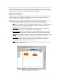
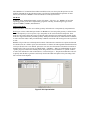
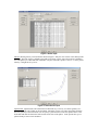
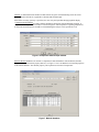
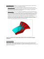
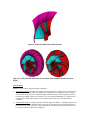
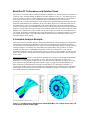
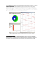
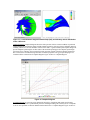
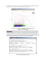
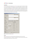
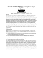
BladePro-CF: An ANSYS-based Impeller Analysis System Dr. Wangming Lu Mark L. Redding Avinash V. Sarlashkar Impact Technologies, LLC, Rochester, NY 14623, U.S.A Abstract This paper presents the architecture and capabilities of BladePro-CF, an ANSYS based analysis system developed to assist engineers in the structural assessment of radial and mixed-flow impellers. The automated tasks include: finite element model generation, boundary condition application, file handling and job submission and queuing of analysis jobs, and impeller-specific post-processing tools. The F.E. model generation features both open and closed (shrouded) impellers, multiple splitter blades, hub geometries with arbitrary back-plane profiles, variable fillet radii at both hub and shroud surfaces, user controllable mesh densities, and definition of blade surfaces using multiple streamlines. Also, both single sector and full wheel models can be generated. The analysis capabilities include steady and vibratory stress calculation, frequency and mode shape calculation, and low- and high-cycle fatigue life predictions. BladePro-CF includes impeller-specific post-processing capabilities such as intuitive stress and displacement viewing, animated mode shape plotting, auto-generated interference and Campbell diagrams. This paper uses a realworld application to demonstrate these capabilities. BladePro-CF can be primarily used as an analytical tool for facilitating the design of structurally sound wheels, a diagnostic tool for doing Root Cause Analysis (RCA) to explain why a blade, or wheel, has failed, and a redesign tool to confirm the improvement of an existing design. Introduction BladePro-CF has evolved from the standalone impeller analysis program IMPRO. The transition from IMPRO to BladePro-CF is driven by a variety of enhanced capabilities offered by the ANSYS program. These enhanced capabilities include: Continuous development of fast and efficient solvers capable of handling large-scale problems on the most current hardware and operating system technologies, Built-in Tcl-Tk interpreter providing native support for graphical user interface development, Ability of the native Tcl-Tk interpreter to access internal ANSYS data items necessary for model generation, boundary condition application and post-processing, Continuous enhancements to post-processing functionality The end-user for BladePro-CF is anyone involved in design, testing, and/or failure analysis of compressor wheels. BladePro-CF provides the end users with a menu driven, easy-to-use analysis tool. The point-andclick interfaces are provided for data input, model generation, analysis, and post-processing. In addition, users are given the necessary control over the FE model mesh densities. This mesh control is important for users during their design iterations since it will allow users to focus on the result variation exclusively caused by the design variations, instead of variations in mesh size and topology. Currently, BladePro-CF’s analysis tools include steady stress analysis with loading due to centrifugal force and/or aerodynamic force, modal analysis at any impeller speed, harmonic response analysis, and fatigue life estimation. To help users evaluate the structural integrity of a proposed design from various aspects, BladePro-CF provides the turbomachinery-specific post-processing tools to generate the Interference Diagram, the Campbell Diagram, and the Goodman Diagram. The Goodman diagram is provided for each node in the model. This paper is organized as follows. First, the general architecture of BladePro-CF and the main features within each menu are described. Then, the analysis capabilities of BladePro-CF are discussed. Next, the comparison between BladePro-CF over IMPRO, mainly in terms of solution time required, is presented. This is followed by representative results from analysis of a real-life impeller. General Architecture BladePro-CF has four modules: Model input, Model generation, Analysis, and Post-processing. Model generation module uses a combination of FORTRAN, C & ANSYS APDL. The user interfaces are developed using the native ANSYS support for Tcl/Tk. As shown in Figure 1 BladePro-CF is launched from within ANSYS by clicking “BladePro-CF” in the ANSYS toolbar. As shown in Figure 1, the main menu contains six items as described below: 1. File: BladePro-CF has the capability to import certain types of files exported by other complementary programs such as TurboGrid, IMPRO. BladePro-CF relies on filename extensions to associate files with certain programs. Once the file is imported, it should be saved into a BladePro-CF file, with an extension name BPR. 2. Model Input: This menu allows the user to define component geometries including airfoil, cutback, shroud, and hub, etc. Aerodynamic force can be defined as well. 3. Generate Model: This menu generates the finite element model and associated user-specified boundary conditions. BladePro-CF can generate both single-sector and full-wheel FE models. 4. Analysis: This menu launches a variety of analysis types including steady stress analysis, modal analysis at any impeller speed, harmonic response analysis, and fatigue life estimation. 5. Post process: BladePro-CF provides users with powerful and intuitive post-processing capabilities of FE results. The post-processing functions available under a specific analysis scenario depend on the type of analysis users conducted. 6. Help: Html-based on-line user manual is provided. Additionally, hitting F1 provides a context sensitive help for all the dialogues. BladePro-CF button BladePro-CF main menu Figure 1. BladePro-CF main menu Since BladePro-CF is launched from within an ANSYS session, user always has the option to use the ANSYS command line or the pull-down menus to perform any standard ANSYS operations. In what follows, the functions of BladePro-CF are described on a menu-by-menu basis. File Menu: In addition to the standard functionality such as “File Open”, “File Save”, etc., BladePro-CF provides importing geometry from other complementary programs. Currently, the following file types can be imported: IMPRO, COMIG, and TurboGrid. Model Input Menu: Model Input Menu allows the user to define geometry information on a component-by-component basis. Hub: Figure 2 shows a hub data input window. In BladePro-CF, the hub profile geometry is defined in the Radial-Axial plane by a series of points Up to 200 points can be used to define the hub profile. These points are only used to define the exterior of the hub profile along the bore and back plane; the hub profile in the flow region is defined by the blade geometry. Each point is defined by its radial and axial coordinate, as well as the fillet radius at that point. Boundary conditions associated with each keypoint can be specified as well.. BladePro-CF provides users with ample mesh controls. The hub mesh control has two options: default and user-defined. For the “default” option, the total numbers of elements in both tangential and radial directions can be specified. For the “user defined” option, the users can select the number of elements on each line of the hub profile. Then, users need to go to Model Input -> Hub Data -> Hub User-Defined Mesh to run the “qmesh” program, which meshes the hub portion using a built-in free-mesh manner. A “qmesh” window, as well as the resultant free mesh of the hub face, is shown in Figure 3. The qmesh module allows the user to quickly mesh the hub to generate a satisfactory mesh in the radial-axial plane before proceeding with a full 3-D mesh for the impeller. Figure 2. Hub input window Figure 3. "Qmesh" window Airfoil: Figure 4 shows the airfoil input window. BladePro-CF defines a 3D airfoil geometry using multiple streamlines, with each streamline defined by a series of points. For a given input section, each streamline is a “mean” line between the corresponding suction-side and pressure-side curves . Each point on this “mean” line has radial and axial coordinate, an angle and associated normal thickness (R-Z-Theta-Thickness). Additionally, a fillet radius can be specified for pressure and suction sides. For each streamline up to 100 points can be specified. The streamlines can be viewed individually or multiple streamlines can be stacked and viewed together. The airfoil input window also allows the user to specify mesh densities and the number of airfoil master degrees of freedom used in the modal analysis. BladePro-CF allows the user to define the so-called flow cut. Flow cut is essentially a cutting line, above which, the portion of airfoil defined by the input streamlines will be removed. This feature allows a convenient way to quickly generate models from the same basic geometry but for different flow rates. Figure 4. Airfoil input Shroud: Shroud geometry can be defined as shown in Figure 5. Only the outer surface of the shroud profile is defined. The inner surface is defined by the blade tip geometry. Again, each point location is defined in the radial plane by its radial and axial coordinates. Any two consecutive points “I” and “I+1” can be joined either by a straight line or by an arc. Figure 5. Shroud/cover input Splitter blade: Splitter blades can be defined in two different ways. One way is to define geometry of a splitter blade in the same fashion as the main blade. Alternately, for the cases where the splitter blade has the same geometry as the main blade, user can specify a pitch fraction to locate the splitter relative to the main blade and then also define the axial location for the start of the splitter. At the present time, up to 3 splitter blades per sector can be modeled. Cutback: A cutback defines the number of blade stations to ignore when determining where the actual geometry begins and ends. It is applicable to shroud, blade and hub input. After all the necessary geometry is specified, user can verify the input data through graphical display. Component model material: For finite element calculation, appropriate material should be assigned. A component material specification window is shown in Figure 6. The temperatures (operating temperature) at which the material properties should be evaluated during the analysis can be specified as well. Figure 6. Component material input window Material database: BladePro-CF contains a comprehensive material database with mechanical, thermal, fatigue and Goodman material property data sets, see Figure 7. Users can add their own material properties to the material database. The material property can be plotted as a function of temperature. Figure 7. Material database Some additional features: BladePro-CF also supports modeling the following features: multiple splitter blades, and definition of airfoil surface using multiple streamlines. Multiple splitter blades: Splitter blades in an impeller can help control the flow induced vibration. Under most circumstances, one splitter is sufficient. The impellers with more than one splitter are rare, but they do appear in some industries. Currently, BladePro-CF can model up to 3 splitter blades. Figure 8 shows one impeller with 2 splitter blades. Multiple streamlines: This is a newly added feature of BladePro-CF. Previously, the airfoil surfaces are constructed based on a series of straight-line stations from shroud to hub. With this new capability, however, one station line is generally represented by a curved line that is defined by a series of points, each from one streamline to which it belongs. Users’ geometry input provides a straightforward construction of a “mean” airfoil surface. An advanced surface construction algorithm is developed to construct both pressure and suction surface based on this “mean” surface and the thickness distributions, as well as other model geometry data. The splitter blade 2 in Figure 8, for instance, has a curved surface that is defined using multiple streamlines. The definition of airfoil using multiple streamlines allows the modeling of a generic curved airfoil surface. Figure 8. An impeller with 2 splitter blades. Blade surfaces were defined by multiple streamlines Generate Model Menu: Figure 9 displays a typical impeller FE model. In this figure only one sector model is generated. Some impellers may have shroud, and/or splitter blades. For example, the impeller shown in Figure 9 has a shroud and splitter blades. In addition, BladePro-CF supports full-wheel model generation. A full wheel FE model is shown in Figure 10. Figure 9. A typical impeller finite element model Figure 10. A full wheel FE model with shroud shown (left), and with shroud not shown (right) Analysis Menu: BladePro-CF provides the following analysis capabilities: 1. Static Stress Analysis: The static stress analysis can be conducted for a single sector or a full wheel FE model. Supported loads include centrifugal load, aerodynamic forces and thermal loads. If a single sector model is used, the cyclic constraint boundary condition and cyclic load are applied. Non-cyclic load cannot be applied. ANSYS cyclic analysis is not used. Instead, in BladePro-CF, ANSYS macros are developed to implement the static stress calculation based on the cyclic constraint boundary conditions. 2. 0 RPM Modal Analysis: Natural frequencies and mode shapes at 0 RPM, i.e., standing frequencies can be calculated in Blade-CF. Multiple natural frequencies are calculated for each circumferential wave pattern (harmonic index). Typically, as part of FE model verification, the predicted modal results will be compared with the results from a standing test. 3. At-speed Modal Analysis: Likewise, natural frequencies and mode shapes can be calculated at any shaft speed. Compared to the 0RPM frequencies and mode shapes, the at-speed calculation includes the effects of stress stiffening, spin softening and temperature at the operating speed. Typically, modal analysis is performed at multiple speeds and a Campbell diagram generated to identify any potentially resonant modes in the operating speed range for the impeller. 4. Harmonic Response Analysis: The Campbell diagram facilitates the identification of potential resonances in the operating speed range for the impeller. However, it does not provide information about the expected level of vibratory stresses and their distribution throughout the impeller. BladeProCF, the harmonic calculation is based on the principle of modal superposition, and therefore, a modal analysis is needed prior to the corresponding harmonic response calculation. It is mainly used to calculate the vibratory stress when the structure is excited at one potential resonance frequency. Both the stimulus ratio and damping can be specified. For a real engineering analysis the requirements of higher vibratory stress can be as follows. The coincidence of the natural frequency of a rotating impeller and the frequency of an excitation, for example, that caused by inlet guide vanes. Strong modal coupling between the mode shape and the excitation force pattern. BladePro-CF facilitates this check by classifying the calculated modes on the basis of “nodal diameters” or the “harmonic content”. Strong harmonic stimulus and low damping. 5. Fatigue Analysis: BladePro-CF provides two approaches to fatigue analysis, the first approach is a stress-based approach while the second approach is a strain-based approach. The first approach is the traditional Goodman diagram. BladePro-CF plots each of the nodes on the Goodman diagram. In BladePro-CF, the Goodman diagram can be simultaneously plotted using vibratory stress responses from up to 5 modes. Vibratory stress response for each of the modes is plotted independently. This facilitates easy identification of critical modes. Further, the user can plot the Goodman diagram for a set of nodes from part of the FE model, for example, the shroud. This is very convenient in identifying critical stresses locations for each mode of vibration. The second approach uses the local-strain methodology for fatigue life estimation. The local-strain approach is able to handle material damage due to both the low-cycle fatigue (LCF) and the high-cycle fatigue (HCF). Typcially, high bore stresses would require LCF analysis to address material damage due to start/stop cycles. Likewise, vibratory stresses in the airfoil due to a potentially resonant mode will require HCF analysis. The localstrain module provides the option to use either Morrow’s method or Manson & Halford ‘s method to account for mean stress effects. For any of the analyses above, the necessary boundary conditions are generated during the FE model generation. The user needs to only provide minimum information to initiate the analysis. For example, the RPM at which, the stress, or natural frequencies need to be calculated. Additionally, BladePro-CF allows the user to access solution related ANSYS controls, such as the selection of solver, the number of processors to use etc.. Post-Processing Menu: BladePro-CF offers post-processing tools that are specific to turbomachinery design / analysis. The fundamental considerations in the design process of an impeller are the static stresses (typically high in the bore), the speed / frequency margins and vibratory stress response. Depending on the application, an impeller may operate at constant speed or may operate at any speed over a range of speeds. In the case of a constant-speed machine, calculation of frequency margins is important. In the case of a variable speed machine, speed margins from potentially resonant modes as well as the corresponding magnitude of resonant stresses is important. BladePro-CF offers the following post-processing information that is specific to design / analysis of turbomachinery. Automatic generation of Interference Diagram to check for frequency margins at a constant operating speed. Automatic generation of Campbell diagram. Mode shape animation for convenient mode classification. BladePro-CF Performance and Solution Times This section is concerned with the solution performance of BladePro-CF. The calculation is performed on a 2 GHz PC with 1.5G RAM, running on Windows NT/2000. ANSYS version is 7.1. The model generation times are typically less than 15 seconds and therefore, only elapsed time for different types of solutions is of relevance. Over the last 5-10 years, ANSYS has made a tremendous progress so far as solver technologies are concerned. This progress is quite evident in the significant reduction in solution times for both static and modal analysis. Furthermore, the use of the Block Lanczos solver has allowed the users to run modal analyses with ever increasing DOFs in the model and therefore, has improved the prediction accuracy. Our experience shows that Block Lanczos solver is the optimum choice for both static and modal analysis. For static analysis on a typical single-sector model FE model with 2744 elements and 9078 nodes, BladePro-CF’s solution time is only 8 seconds. For the same model, the solution time for modal analysis is 116 seconds. It should be noted that this time saving depends on the size of FE model of interest, as well as the solution related controls. It is evident that ANSYS’ advanced solution technologies enable users to obtain the analysis results quickly. A Complete Analysis Example This section presents a complete analysis example using BladePro-CF. The main purpose is to demonstrate typical analysis procedure using BladePro-CF to perform a structural integrity assessment. The analysis covered in this section includes steady stress analysis, at-speed modal analysis, harmonic response analysis, and fatigue analysis. The impeller has 9 main blades and 9 splitter blades. The tip diameter is 221mm. Nominal operating speed is 18000 RPM. The impeller is made of Cast Aluminum C-355.0 with the following mechanical properties: Yield strength: 30 ksi (0.2% offset), Young’s modulus: 10.29E3 ksi, and density of 0.097 lb/in^3. All reported stresses and deformations are based on the linear elastic assumption for the model. Steady Stress Analysis: Figure 11 (left) shows the distribution of von Mises stress throughout the impeller. The maximum computed stress is 80.5 MPa (11.7 ksi). This is an acceptable stress level for Cast Aluminum C-355.0 with yield strength of 30 ksi. As mentioned earlier, BladePro-CF supports the steady stress analysis for the FE model of the whole impeller. Figure 11 (right) shows the distribution of von Mises results that are obtained based on the finite element analysis of a full impeller FE model. As expected, the von Mises stress results predicted from a full model analysis are identical to those predicted from a single-sector model. However, the analysis time required by a single sector analysis is only about 20% of that required for a full model analysis. Figure 11. von Mises stress distribution at 18000 RPM (MPa): For a single sector (left), and for the whole impeller model (right). At-speed Modal Analysis: Based on at speed modal analysis results, an Interference Diagram, as shown in Figure 12, is automatically created by BladePro-CF. Figure 12 also shows the mode shape and the harmonic content for the selected mode. Mode shape animation helps user visualize the deformation pattern around the impeller. The display of harmonic contents of a mode can help users to find whether it will be excited by a given external excitation pattern, for example, inlet guide vane excitation. The ultimate goal is to avoid impeller resonance that can lead to high vibratory stress. Figure 12. Mode shape animation and generation of interference diagram Harmonic Response Analysis: It is a straightforward process to focus on several critical modes that are identified by using the Interference and the Campbell diagrams. Figure 13 (left) shows a one nodal diameter mode in the second family mode. The modal animation indicates that the motion is dominated by the airfoil flap-wise vibration at the inlet regions. The vibratory stress is shown in Figure 13 (right). Figure 13. 1-nodal diameter tangential mode shape (left), and vibratory stress distribution in the 1-ND mode Campbell Diagram: Campbell diagram shows the shaft speeds at which a resonant condition is predicted. Campbell diagram considers the change in blade natural frequencies with speed (stress stiffening and spin softening effects) as well as the harmonic content of the mode. A good constant-speed impeller design will provide adequate speed margins on either sides of the nominal operating speed. Adequate speed margin will assure in low vibratory stresses and will provide protection against variation in impeller frequencies due to inaccuracies in manufacturing and scatter in material properties. The gyroscopic damping is not considered in the construction of Campbell diagram. Figure 14 shows a Campbell diagram. Figure 14. Campbell diagram Goodman Diagram: It is used to assess mechanical integrity by considering both steady and vibratory stresses. The steady stress is predominantly from the centrifugal loading. The vibratory stress corresponds to one or more potential resonances identified on the Interference / Campbell diagram. Figure 15 shows a Goodman diagram where vibratory stresses for three modes are plotted concurrently. BladePro-CF allows the definition of the Goodman envelope with multiple straight line segments.. Figure 15. Goodman diagram Fatigue Analysis: In BladePro-CF, as an alternative to the Goodman diagram, the strain-life approach is available to predict fatigue life. This approach will be typically used to predict LCF damage at locations with high static stresses such as notches or fillets. The input to the local-strain fatigue module consists of elastic stress-strain history over a certain time block. The fatigue analysis module generates a detailed report that describes the following information: maximum/minimum true stress/strain throughout the entire loading history, damage caused by LCF and HCF respectively, total damage throughout service time, and number of blocks prior to the failure. An example of this report is shown in Figure 16. Figure 16. Report of fatigue analysis Summary This paper summarizes the architecture and analysis capabilities of BladePro-CF, an ANSYS based impeller wheel analysis program. The development of BladePro-CF fully takes advantage of the strengths of ANSYS such as robust and fast solvers, efficient memory usage, and powerful post-processing capabilities. ANSYS APDL language has been used extensively throughout this software. Tcl/Tk interpreter within ANSYS has been used extensively to develop the graphical user interface. BladePro-CF can be made available to run on any ANSYS-supported platform. In summary, BladePro-CF clearly shows how to effectively leverage vertical integration capabilities within ANSYS to build custom applications. BladePro-CF can be effectively used as: An analysis tool to ensure mechanical integrity of impeller wheels A diagnostic tool to conduct Root Cause Analysis (RCA) to explain why a blade or a wheel failed,. A redesign tool to verify proposed changes to a design. Acknowledgements The authors would like to acknowledge the contributions by Ben Atkinson, Ryuichi Machida and other team members in the continued development of BladePro-CF. References 1. ANSYS 2000, APDL Programmers Guide, ANSYS Inc. 2. ANSYS. 2000, Guide to ANSYS User Programmable Features, ANSYS Inc. 3. ANSYS 2000, Guide to Interfacing with ANSYS, ANSYS Inc. 4. Welch, B. 1997, Practical Programming in Tcl and Tk, Prentice Hall 5. ANSYS 2000, ANSYS Online Documentation, ANSYS Inc. 6. Bannantine, J.A., Comer, J.J. and Handrock, J.L. 1990, Fundamentals of Metal Fatigue Analysis, Prentice Hall.