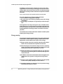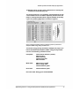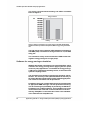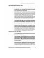
1
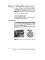
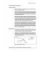
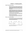
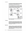
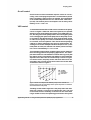
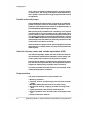
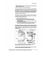
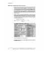
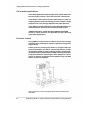
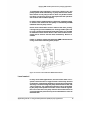
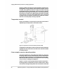
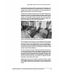
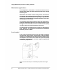
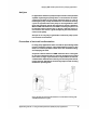
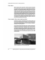
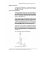
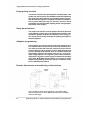
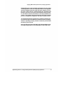
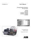
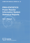
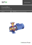
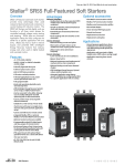
ABB drives
Using variable speed drives (VSDs)
in pump applications
2
Application guide No. 2 - Using variable speed drives (VSDs) in pump applications
Contents
Chapter 1 - Introduction ......................................................................... 5
Chapter 2 - The basic function of pumps ............................................... 6
Centrifugal pumps .......................................................................................... 6
Terminology in this section ............................................................................. 7
Common terms .............................................................................................. 7
Pump curves..................................................................................................
7 Affinity laws ....................................................................................................
8
Chapter 3 - Pumping system .................................................................. 9
Pump as a part of the process ....................................................................... 9
Different flow control methods ........................................................................ 9
Throttling ...................................................................................................... 10
Bypassing .................................................................................................... 10
On-off control ............................................................................................... 11
VSD control ................................................................................................. 11
Parallel and serial pumps ............................................................................. 12
Selection of pump, motor and variable speed drive (VSD) ............................ 12
Pump selection ............................................................................................ 12
Motor and variable speed drive selection...................................................... 14
Chapter 4 - Variable speed drive benefits with pump applications .......15
Life cycle cost (LCC) .................................................................................... 15
Energy saving .............................................................................................. 16
Software for energy savings calculation ........................................................ 18
Low maintenance and repair cost ................................................................ 19
Additional benefits with VSDs ...................................................................... 19
Chapter 5 - Applying variable speed drives to pumping applications ... 21
Process control parameters ......................................................................... 21
Clean water applications .............................................................................. 22
Pressure control ........................................................................................... 22
Level control................................................................................................. 23
Temperature control ..................................................................................... 24
Case example: pressure boosting station ..................................................... 24
Wastewater applications .............................................................................. 26
Level control ................................................................................................ 26
Anti-jam .......................................................................................................
27 Prevention of tank wall sedimentation ..........................................................
27 Flush effect ..................................................................................................
28
Application guide No. 2 - Using variable speed drives (VSDs) in pump applications
3
Case example: Storm water pumping station ............................................... 28
Additional functions ...................................................................................... 29
Flow calculation function .............................................................................. 29
Pump priority function .................................................................................. 30
Sleep boost function .................................................................................... 30
Adaptive programming ................................................................................. 30
Remote data access and monitoring via the Internet .................................... 30
Chapter 6 - Bibliography ....................................................................... 32
Chapter 7 - Symbols and definitions ..................................................... 33
Definitions .................................................................................................... 33
Index .......... ........................................................................................... 35
4
Application guide No. 2 - Using variable speed drives (VSDs) in pump applications
Chapter 1 - Introduction
The purpose of this Application guide is to give design and
project engineers and any other interested parties the basic
information for selecting the correct variable speed drive (VSD)
system for pump installations in industrial, public and domestic
applications.
Pumps are one of the most common variable speed drive (VSD)
system applications and special interest has focused on improving their energy efficiency by using variable speed control instead of throttling or other less efficient flow control methods.
Pumps are the single largest user of electricity in industry in the
European Union, consuming 160 TWh per annum of electricity
and accounting for 79 million tonnes of carbon dioxide (CO2)
emissions.
The content of this guide has been kept as practical as possible,
without going into too much theoretical depth. The symbols and
definitions used are explained at the end of this document.
Application guide No. 2 - Using variable speed drives (VSDs) in pump applications
5
Chapter 2 - The basic function of pumps
The purpose of pumps is to transfer liquids from a source to a
destination. A common example is filling a high level reservoir
or increasing liquid pressure. Other examples are filling a pressurized tank or circulating liquid around a system as a means
of heat transfer.
There are two main categories of pumps:
• Centrifugal (rotodynamic) pumps
• Positive displacement pumps
This Application guide focuses on centrifugal pumps. These
account for 80% of all industrial pumps.
Centrifugal pumps
The centrifugal pump (Figure 1.) is a mechanical device for increasing the pressure of liquid. In passing through the pump, the
liquid is accelerated in the impeller, discharging into the casing
at high velocity. This energy used is converted into pressure of
the liquid as effectively as possible.
Source: Variable speed pumping, Europump and Hydraulic
Institute, 2004
Discharge
Impeller
Casing
Inlet
Volute
Figure 1. Centrifugal pump: the most common pump type in industry and
public utilities.
6
Application guide No. 2 - Using variable speed drives (VSDs) in pump applications
The basic function of pumps
Terminology in this section
Common terms
Before describing how a pump operates, it is useful to understand some key terminology:
Head - The net work done on a unit weight of water by the pump
impeller. It is the amount of energy added to the water between
the suction and discharge sides of the pump. Pump head is
measured as pressure difference between the discharge and
suction sides of the pump.
Static head - The vertical distance from the water level at the
source to the highest point where the water must be delivered.
It is the sum of static lift and static discharge. Static head is
independent of the system discharge and is constant for all
values of discharge. However, it is possible that the static head
may vary over time due to the changes in the system.
Operating point - A centrifugal pump can operate at a combination of head and discharge points given by its pump curve (see
below). The particular combination of head and discharge at
which a pump is operating is called the pump's operating point.
Once this point is determined, brake power, efficiency, and net
positive suction head required for the pump can be obtained
from the set of pump curves.
Pump curves
The pump curves in Figure 2 show the technical performance
of the pump. The horizontal axis shows the flow rate and the
vertical axis shows the head and power generated.
A system curve, normally plotted together with the pump curve
describes the static head and resistance of the pipeline. The
operating point of the pump is at the intersection of the system
curve and the pump curve.
Head/ Power
Pump curve
System curve
Power curve
Flow
Figure 2. Pump performance curves.
Application guide No. 2 - Using variable speed drives (VSDs) in pump applications
7
The basic function of pumps
Affinity laws
As stated before, pumps are mechanical devices for increasing
the pressure of liquid.
The affinity laws (Table 1) below describe the relation between
the rotational speed of the pump (n), flow rate (Q), head generated (H) and power absorbed (P).
Speed and flow are directly
proportional - Flow
Flow
Head is proportional to the
square of the speed - Head
n
Head H1= 1
H 2 n2
Power is proportional to the
speed or flow cubed - Power
Q 1 n1
Q2= n2
2
3
Power P1 =
P2
Table 1: Affinity laws
n1
n2
8
Application guide No. 2 - Using variable speed drives (VSDs) in pump applications
Chapter 3 - Pumping system
Pump as a part of the process
When in use, the pumps are always part of a pumping system.
A pumping system is usually a network of pipes, tanks, valves
and other system parts. The receiver is usually at a higher geographic level than the supply of the system. These parts can be
also on the same level, as in the case of a closed circuit heat
transfer system.
Pumping systems nearly always require a variation of flow rate.
Examples include the daily cycle in the consumption of drinking water, the varying process demand for a liquid or seasonal
heating demand. However, the variation required may be in the
pump head, such as for cyclical changes in process pressure,
or pumping to tanks with a variable liquid level.
In spite of the variations, the pump capacity is selected according to the maximum flow and head or even to the future needs,
perhaps with a certain safety margin.
The average pumping capacity may be only a fraction of the
maximum capacity and this will require some kind of control.
Different flow control methods
There are several different methods to match the flow to the
system requirements. The most common flow control methods
of pumps are throttling, bypassing, on-off control and VSD
control. These are illustrated in Figure 3.
Figure 3. Illustrations of pump flow control methods. Left to right: throttling,
bypassing, on-off control and VSD control.
Application guide No. 2 - Using variable speed drives (VSDs) in pump applications
9
Pumping system
The relative power consumption of the different control methods
can be estimated from the area between the x and y-axes and
the operating point. It is using the formula P=Q x H.
In the following example, Figure 4, the relative power consumption on an average flow rate of 70% is calculated with different control methods. More detailed explanations on power
consumption and energy savings relating to different pump
applications are described in the following chapters.
Throttling
Bypassing
On-off control
VSD control
Pump runs
70% of the time P=10 *
10 = 100
Pump is off 30% of the
time
Control
Throttling
Bypassing
On-off control
VSD control
Energy
89
82
70
45
Figure 4. The power consumption of the four most common flow control
methods for centrifugal pumps.
Throttling
Throttle control is the most commonly used method. The flow
caused by the constant speed pump is reduced by increasing
the losses in the system by closing the valve. In the example
in Figure 4 the operating point is moved from (Q = 10, H = 10)
to (Q = 7, H = 12.7). The relative power consumption can be
calculated by P = 7 x 12.7 = 89.
Bypassing
Although not commonly used, bypassing is applied mainly to
circulation pumps. The flow output to the system is reduced by
bypassing part of the pump discharge flow to the pump suction.
This means that the total flow increases (from 10 to 12.4), but the
head decreases (from 10 to 6.6). The relative power consumption is P = 12.4 x 6.6 = 82.
10
Application guide No. 2 - Using variable speed drives (VSDs) in pump applications
Pumping system
On-off control
On-off control is often used where stepless control is not necessary, such as keeping the pressure in a tank between preset
limits. The pump is either running or stopped. The average flow
is the relationship between the "on" time and the "total" time
(on+off). The relative power consumption can be easily calculated by P = 0.7 x 100 = 70.
VSD control
To understand the benefits of VSD control consider to the pump
curves in Figure 4. With low static head systems, the optimal
efficiency of the pump follows the system curve. With VSD control, the duty point of the pump follows the unchanged system
curve. Changing the speed of the pump moves the pump curves
in accordance with the affinity laws. If the pump impeller speed
is reduced, the pump curve moves downwards. If the speed
is increased, it moves upwards. This means that the pumping
capacity is exactly matched to the process requirements. According to our earlier example both flow rate (from 10 to 7) and
head (from 10 to 6.4) are reduced. The relative power consumption can be calculated by P = 7 x 6.4 = 45.
This example shows that the variable speed control method is
the most energy efficient for pumping applications. The examples discussed were calculated for one flow rate only (70%), but
the relative power consumption with different control methods
depends on the flow rate. This relationship is shown in Figure
5. In these curves, the pump, motor and drive efficiencies are
also taken into account and for that reason the results differ
somewhat to those in Figure 4.
Throttling
Bypassing
On-off control
VSD control
Flow %
Figure 5. Power consumption with different pump control methods as a
function of flow rate. The percentage values of flow and power are related to
the nominal values of the pump.
Throttling control leads to high loss in the pump and in the valve
when the system is running at a reduced flow rate. The loss
in the motor remains relatively constant over the whole flow
range. In VSD control, the operating point follows the system
Application guide No. 2 - Using variable speed drives (VSDs) in pump applications
11
Pumping system
curve, which is optimal for pump efficiency. In general, based
on affinity laws, the energy consumption drops dramatically
when speed is reduced. The energy savings with VSD control
are significant.
Parallel and serial pumps
If the available flow capacity with a single pump is not sufficient,
parallel connection of two or more pumps is possible. It is important to install back pressure valves for all parallel pumps, to
avoid backwards flow through the pumps.
With parallel pump installation the redundancy of the system
is much higher. If one of the pumps is lost in the system, other
pumps can take its place and continue operation. Downtime is
very limited, depending on how fast the replacement is carried
out. With ABB industrial drives the parallel connection of drives
detects faulty units and makes any necessary corrections in the
control loop in less than one second.
Serial connection of pumps can be used in high-pressure system
applications, for example where one pump cannot produce the
head required.
Selection of pump, motor and variable speed drive (VSD)
The selection of pumps, motors and drives is based on the process information. Sometimes the information can be simply: "We
need to pump water at 300 l/s, please quote for a pump".
Even though the pump is a simple machine, proper pump selection calls for more input data. There are many selection tools to
support the dimensioning of pumps, motors and drives.
The motor and VSD are dimensioned to run the pump under
normal pump operation conditions.
Pump selection
The general requirements for pump selection are:
• Working conditions
• Capacity, suction and discharge pressures with variation
ranges
• Maximum differential pressure for the pump casing
• Exceptional starting, stopping and other running conditions
• Liquid specification with density, temperature etc.
• Suction conditions such as suction head, suction pipe losses
etc.
• Pump construction material
12
Application guide No. 2 - Using variable speed drives (VSDs) in pump applications
Pumping system
• System description, e.g. single, parallel or serial connection
with some other pump
• Special conditions in the mounting space
The required capacity can often be achieved by several different
pump types with the same or different speed. The selection has
to be made, for instance, between a higher speed pump with
low initial cost and a lower speed pump with lower maintenance
costs. The use of pump curves, as printed in a manufacturer's
catalogue, is shown in Figure 6.
For example, to select a pump for a before mentioned quote
"We need to pump water at 300 l/s, please quote for a pump" the
selection steps are the following.
1. find the required flow, 300 l/s
2. move upwards to match the required head, 30 m
3. the required performance is achieved with pump of
1400 rpm speed
4. to see the power needed move down to the lower curve
set along with 300l/s line
5. when crossing the 1400 rpm curve move to left to read
the power needed at the operating point (110 kW)
The selected pump is the smallest capable for the operating
point required. If we know that there is no need for higher capacity, either now or in the future, there is no need to choose
a bigger pump. The bigger pump leads to higher initial and
operating costs.
closed 864 Z6
open 864 Z5
(m)
(ft) (m)
η%
(ft) (m)
η%
2
(hp) (kW)
(hp) (kW)
3
1
4
5
Figure 6. An example of pump curves. Left: Pump with three different
impeller diameters. Right: Pump with six different speeds.
For the variable speed application example above, a motor
selection can be made for 110 kW/1400 rpm.
Application guide No. 2 - Using variable speed drives (VSDs) in pump applications
13
Pumping system
Motor and variable speed drive selection
Motor and drive manufacturers have developed software tools
for motor and drive selection. ABB has a DriveSize tool, which
can be used for the pump case above. The results are similar
to manual selection. The tool has a database of ABB motors,
drives and transformers so its output is an exact selection with
type designations. The DriveSize tool can be downloaded from
the Internet at www.abb.com, and then entering "DriveSize" in
the search box.
Figure 7 shows an example of DriveSize 2.5 motor selection.
Because the pump loading torque is very low at lower speeds,
the maximum torque is critical for motor selection. In this case
we need to check that the motor torque (Tm) at 1400 rpm is higher
than the pump torque (Tp).
Tp=
Nm
9550xPp 9550x110kW
n
=
= 750
1400rpm
As a result, the pump torque is 750 Nm. In this case the selected
motor M3BP 315 SMB 4 has 848 Nm torque.
Figure 7. The selection window of DriveSize 2.5.
DriveSize also selected a suitable VSD for the pump, which is
ACS800-02-0170-3.
14
Application guide No. 2 - Using variable speed drives (VSDs) in pump applications
Chapter 4 - Variable speed drive
benefits with pump applications
Pumping applications represent a significant opportunity for applying VSDs in new, as well as retrofit installations. The majority
of pumping applications need to be controlled. It is unlikely that
a pump will run continuously at a maximum speed.
VSDs are crucial when limiting the life cycle costs (LCC) of a
pump station. The three main costs are energy, initial investment
and maintenance.
Many analyses show that energy consumption is the dominating
element of the LCC, especially if pumps run more than 2,000 hours
per year. The investment cost of the equipment needed (variable
speed drives, motors and pumps) is relatively low when compared
to the total LCC. Maintenance is the third main cost component.
Active control using a VSD works as a means of preventive maintenance, limiting maintenance costs in many ways.
VSD control has several benefits in pumping systems. The most
important is energy saving. Accurate control of the pump system
is another benefit. With VSDs running the pump system, linking to other automation systems is easy by means of common
fieldbus gateways.
The following chapters give more detailed descriptions of these
benefits.
Life cycle cost (LCC)
LCC analysis is a method of calculating the cost of a system over
its entire life span. The analysis of a typical system includes initial
costs, installation and commissioning costs, energy, operation,
maintenance and repair costs as well as down time, environmental, decommissioning and disposal costs.
Many organizations only consider the initial purchase and installation cost of a system. It is in the interest of the plant designer
or manager to evaluate the LCC of different solutions before
installing major new equipment or carrying out a major overhaul. This evaluation will identify the most financially attractive
alternatives. As national and global markets continue to become
more competitive, organizations must continually seek cost savings that will improve the profitability of their operations. Plant
equipment operations are receiving particular attention as a
source of cost savings, especially minimizing energy consumption and plant downtime.
Application guide No. 2 - Using variable speed drives (VSDs) in pump applications
15
Variable speed drive benefits with pump applications
In addition to the economic reasons for using LCC, many
organizations are becoming increasingly aware of the environmental impact of their businesses and are considering energy
efficiency as one way to reduce emissions and preserve natural
resources.
Source: Pump Life Cycle Costs, Hydraulic Institute, Europump, 2000
Life cycle analysis for pumping systems show that:
• 5% of industrial energy goes to pumps
• 90% of the total cost of owning a pump comes from energy
consumption
• Pump energy consumption can generally be reduced up to
20%
Good guidance for Pump Life Cycle Cost is available from
www.pumps.org. An LCC Analysis for Pumping Systems has
been developed by the Hydraulic Institute (HI), Europump and
the US Department of Energy's Office of Industrial Technologies (OIT)
The website also includes information related to variable speed
pumping and energy savings.
Energy saving
The Hydraulic Institute and Europump have jointly published a
book entitled "Variable Speed Pumping: A Guide to Successful
Applications" which details seven ways to save energy:
1) Design systems with lower capacity and total head requirements. Do not assume these requirements are fixed.
2) Avoid allowing for an excessive margin of error in capacity
and/or total head. It typically will be less expensive to add
pumping capacity later if requirements increase.
3) Despite the tendency to emphasize initial cost, you will save
in the long run by selecting the most efficient pump type and
size at the onset.
4) Use VSDs to avoid losses from throttle valves and bypass lines,
except when the system is designed with high static
heads.
5) Use two or more smaller pumps instead of one larger pump
so that excess pump capacity can be turned off.
6) Use pumps operating as turbines to recover pressure energy
that would otherwise be wasted.
16
Application guide No. 2 - Using variable speed drives (VSDs) in pump applications
Variable speed drive benefits with pump applications
7) Maintain pumps and all system components in virtually new
condition to avoid efficiency loss.
The energy efficiency of a pumping system depends on the
control method used. The VSD is especially efficient when the
pump is running with partial flow. A typical example of the duty
cycles of a pumping application is shown in Figure 8.
Figure 8. A typical operating profile of a pumping system as presented in
PumpSave, ABB's energy saving calculation tool.
The earlier energy saving calculation example (see page 13) is
below calculated with PumpSave, ABB's energy saving calculation tool. The following conditions exsist:
Pump data:
Nominal flow 1000m3/h (~300l/s)
Efficiency 85%
Static head 10m
Nominal head 30m
Max head 45m
Motor data:
Motor power 110 kW
Motor voltage 400V
Nominal efficiency 96%
Drive data:
Nominal efficiency 95%
Economic data: Energy price 0.05 EUR/kWh.
Application guide No. 2 - Using variable speed drives (VSDs) in pump applications
17
Variable speed drive benefits with pump applications
The energy consumed with throttling and VSD is illustrated
below on Figure 9.
Energy Consumed
kWh
Throttling
VSD
Figure 9. Energy consumption of a pump system controlled with throttling
and VSD control as presented in PumpSave, ABB's energy saving calculation
tool.
The total energy saving with the VSD compared to throttling is
202 MWh (46%). The financial savings amount to 10,100 EUR
every year.
This calculation clearly shows the benefit of VSD control with
regard to energy savings for a single pump.
Software for energy savings calculation
ABB has developed a calculation tool called PumpSave, which
estimates the energy savings when applying electric speed
control to pump applications. To estimate the energy savings,
a VSD can be compared to throttling control, on-off control and
hydraulic coupling control.
The calculations are based on typical pump operating characteristics. The accuracy of the input data affects the accuracy of
the results. Results should only be used for estimating purposes.
The results of calculations can be printed out.
PumpSave carries out a simple dimensioning and recommends
an appropriate ABB drive type. The tool provides financial figures for assessing the profitability of purchasing an ABB drive.
PumpSave runs in Microsoft Excel. The PumpSave tool can be
downloaded from www.abb.com/motors&drives and then
entering "PumpSave" in the search box. There is also a detailed
user's manual for the PumpSave tool.
18
Application guide No. 2 - Using variable speed drives (VSDs) in pump applications
Variable speed drive benefits with pump applications
Low maintenance and repair cost
Maintenance and repair costs are one of the main elements in
the LCC analysis. The cost of unexpected downtime and lost
production is a very significant item in the total LCC and can
rival the energy costs. With VSDs, lower maintenance and repair
cost is achieved through the following:
Reduced water hammer effects. Water hammer is caused by
rapid changes in flow. These flow changes are followed by rapid
pressure transients that cause pipes, pipe supports and valves to
be damaged causing leakage. VSDs allow the user to gradually
ramp the acceleration at a safe rate to avoid hammering.
Reduced stress on electrical supply. VSDs always start the
pump motor softly with much lower peak current than direct-online starting that is used with other flow control methods.
Reduced risk for cavitation. Cavitation is a phenomenon that
occurs whenever the static pressure drops below the liquid vapour pressure causing bubbles to collapse with a very high impact force. This force causes surface damage inside the pump.
With a VSD it is possible to monitor the pressure of the incoming
pipeline and take steps if the risk of cavitation is high.
Redundancy. With parallel pumps, each controlled with a VSD,
there are two possibilities to minimize maintenance and repair
costs. Parallel connection means that if one pump fails, the remaining pumps can continue uninterrupted. Another benefit is to
control the running times of each pump to a predefined schedule. This enables the customer to optimize any service breaks,
ensuring that there is always pumping capacity available.
Additional benefits with VSDs
The use of VSDs has many other advantages in process control
applications. These include:
Harmonics. In some countries, power companies set strict limits
on the permissible harmonic content of current and voltage, in
order to prevent damage to equipment in the same environment.
In these situations, ABB low harmonic drives minimize offending harmonics, causing no harmful effect to the power grid,
thereby avoiding penalties while ensuring maximum uptime for
the pumping station.
Easy communication. ABB drives can connect to all major
automation systems. This is achieved with a dedicated gateway concept between the fieldbus systems and ABB drives.
The Ethernet module gives simple access to the drive via the
Application guide No. 2 - Using variable speed drives (VSDs) in pump applications
19
Variable speed drive benefits with pump applications
Internet, communicating via a standard web browser. The user
can set up a virtual monitoring room wherever there is a PC with
an Internet connection or via a simple dial-up modem connection. This enables remote monitoring, configuration, diagnostics
and, when needed, control.
Flexibility in pump selection. Quite often it is difficult to estimate the system parameters in advance and therefore the safety
margins used are too high. This causes additional operational
costs if the required flow and head are lower than estimated. By
using VSDs these over dimensioning problems can be resolved
by running the pump at a lower speed.
Reasonable investment cost. VSDs have developed rapidly
during the last 10 years. The cost of manufacture and subsequent cost of purchase has also fallen dramatically in recent
years. Sometimes it can be less expensive to install a VSD than
a control valve with a PLC system.
Natural part of the control loop. One big advantage in considering a VSD in comparison to a control valve is the elimination of deadband that a control valve introduces into loop
performance.
20
Application guide No. 2 - Using variable speed drives (VSDs) in pump applications
Chapter 5 - Applying variable speed
drives to pumping applications
The majority of pumping applications need to be controlled.
Changing the rotation speed of a centrifugal pump has an effect on the pump's volume flow, generated head and power
consumption.
The design of a pumping system with VSDs requires knowledge
about the process control parameters.
Process control parameters
The parameters to be considered in clean water applications
include:
• Inputs - heads and pressure required, flow and its variations,
required level of the liquid
• Outputs - pressure generated, flow generated
• External influences - temperature change, change in flow,
change of the liquid's properties, floating, breaking or jamming of the pipeline, change in the water consumption rate
The parameters to be considered in waste water applications
include, accordingly:
• Inputs - level of the water, temperature, pH, flow
• Outputs - flow, optimum filling-/emptying time, adjustement
of pH or temperature
• External influences - temperature change, change in flow,
change of the liquid's properties, floating, breaking or jamming of the pipeline
Knowing the above requirements makes it easy to find the
right parameter to be controlled and subsequently optimize
the process.
VSD can handle several analogue and digital inputs and outputs
to control and monitor the pumping process. The large number
of fieldbus options makes it easy to incorporate the drives seamlessly into any automation system.
Some basic control loops in industrial and public pump applications are described later in this chapter.
Application guide No. 2 - Using variable speed drives (VSDs) in pump applications
21
Applying ABB variable speed drives to pumping applications
Clean water applications
Clean water applications require pumps to carry fresh water from
the source (lake, well etc.) to the users (homes, industry etc.).
Clean water is often stored in tanks either before or after undergoing different chemical cleaning processes. Water is finally
pumped to the users through pipelines with stable pressure.
Three different control examples for clean water applications are
described below: pressure, level and temperature control.
''Additional functions'' -section describes additional useful VSD
functions. These functions are applicable for both clean and
waste water applications.
Pressure control
Using VSDs to control pressure reduces the electrical energy
requirements by reducing the amount of hydraulic energy actually produced.
A basic pressure control pump station is equipped with one
pump controlled by one VSD. In some pump stations, pumps
connected in parallel are a more efficient solution. Several parallel pumps can be controlled with one VSD controlling the master
pump and contactors switching the other pumps on and off.
Figure 10 shows a set-up with parallel pumps using one ABB
drive to control three pumps.
Figure 10. Pressure control of a pumping system with one variable speed
drive (VSD).
22
Application guide No. 2 - Using variable speed drives (VSDs) in pump applications
Applying ABB variable speed drives to pumping applications
To guarantee pump operation, even when a fault occurs, the
pump system needs redundancy. In pump stations this means
that a failure of one pump, motor or drive in a parallel installation does not cause a process interruption but the operation
will continue with a limited capacity.
In order to have a replacement for a failed unit, a parallel system
is needed. This means that each pump is controlled by an ABB
industrial drive for pump control.
Drives share information such as status of the drive, priority,
running time, process feedback, etc. through a fiber optic link.
In a ring connection implemented with fiber optics it is possible
to define the actions for the drives in the event of failure of the
optical link in order to achieve 100% redundancy. No PLC is
needed.
Figure 11 shows a system loop with three ABB industrial drives
in ring connection controlling three pumps.
Figure 11. Pressure control with three ABB industrial drives.
Level control
In many clean water applications, the level of the water is a required control function. In a typical level control loop, the level
in the tank is controlled by throttling a control valve at the pump
discharge. The flow through the pump will be between 25% and
75% of capacity. The significant hydraulic energy generated
by the pump is dissipated across the control valve to regulate
the level in the tank. The pump must be also dimensioned to
accommodate the pressure drop associated with the valve at
maximum flow.
Application guide No. 2 - Using variable speed drives (VSDs) in pump applications
23
Applying ABB variable speed drives to pumping applications
Applying a VSD in the loop will control the pump to generate only
the hydraulic energy needed to discharge the required amount
of liquid. This approach reduces energy costs while lowering
pump maintenance requirements. The net result is a system
that reduces operating and maintenance costs by eliminating
the need for a control valve, bypass piping and the associated
energy losses. The level of the water tank can be controlled
using PI control to maintain smooth but accurate level control
with one or several pumps running in parallel.
Temperature control
Figure 12 illustrates a control loop in which flow into a tank is
regulated by the temperature of the tank content.
Figure 12. Temperature control with variable speed drive (VSD).
Temperature of the liquid is used to control the motor speed that
regulates the flow to the tank. An on/off valve must be installed
for safety reasons.
Case example: pressure boosting station
The basic example of a clean water pump station is a pressure
boosting station. It feeds water directly into the distribution
system and seeks to maintain a constant pressure in the pipes.
With smooth VSD control there are no pressure shocks causing
noise, erosion or leakage in the pipeline.
Figure 13 shows a three pump parallel system at pressure
boosting station in Pietarsaari, Finland. A water tower, which
was the main storage facility before the construction of the tank
24
Application guide No. 2 - Using variable speed drives (VSDs) in pump applications
Applying ABB variable speed drives to pumping applications
and pressure boosting station, now serves as a back-up. The
pressure boosting station is equipped with 2 x 75 kW and 1 x
37 kW electric pumps. The station was recently upgraded with
ABB industrial drives to operate the pumps.
Parallel drives enable the system to run with 100% redundancy.
If a defect occurs in one of the pumps, motors or drives, the
others will continue the operation without any interruption. Pump
stations are sometimes located remotely and service activities
might take some time. With redundancy, the pump station operation is trouble-free with minimized downtime.
Figure 13. Pressure boosting station in Pietarsaari, Finland.
The running time of the pumps can be stabilized with the pump
priority function to ensure that the wear and tear of all pumps is
the same. In some cases prioritization can use smaller pumps
during light loading and bigger pumps during heavy loading,
thereby maximizing energy use. In Pietarsaari the smaller 37 kW
pump is used only at night time.
The flow calculation function enables the pumped volume to be
monitored by the VSD, without any additional components. This
is a very useful feature in systems where data about the total
flow during a specific time period is needed. However, this is not
deemed accurate enough for invoicing purposes. In Pietarsaari
the flow measurement result of the drive is compared with the
flow meter. The results are the same.
ABB industrial drives have enabled customers to reduce energy
consumption by about 30%. The pressure in the system is much
more stable, which has reduced leaks as well as maintenance
needs.
Application guide No. 2 - Using variable speed drives (VSDs) in pump applications
25
Applying ABB variable speed drives to pumping applications
Wastewater applications
In this application, wastewater is transferred from the source
(houses, drain wells and other collection points) to the sewage
treatment plant.
Wastewater and rainwater contains solid particles, which have to
be pumped. Actual pumping time and pressure are not important
issues, but there must be sufficient capacity for special cases
(heavy rain) and redundancy to handle situations when one or
more pumps are out of order.
The collection points have tanks from where the wastewater is
pumped to the treatment process. It is crucially important to have
the right level in those tanks, as well as control over the pumps
in order to keep the system operational at all times.
It is important to have stable process conditions in the treatment
plant. However, this guide does not examine the wastewater
treatment process in detail.
Level control
Level control is typically used to control the filling or emptying
of wastewater storage tanks. Single pump or parallel pumps
operate at a favorable point most of the time to minimize energy
consumption. Level control can be used with up to three pumps
and drives in parallel. Figure 14 shows a typical single pump
wastewater pump station.
Figure 14. Level control set-up in a wastewater pump station with a single
pump.
26
Application guide No. 2 - Using variable speed drives (VSDs) in pump applications
Applying ABB variable speed drives to pumping applications
Anti-jam
In applications where the pumped liquid contains small particles
capable of jamming the pump, there is a need to have an active
cleaning procedure for the pump, otherwise there is a risk of
breaking the pump. Pump manufacturers recommend cleaning
cycles for systems where the pump is running between maximum and minimum speeds with aggressive ramps in between.
With an ABB industrial drive, this kind of cleaning sequence can
be activated during motor jam, or during a specific run-on or
run-off time. This is also a good example of preventive maintenance for the pump.
Anti-jam is an easy way to guarantee continuous pump operation in harsh environments.
Prevention of tank wall sedimentation
In many pump applications there is a tank for liquid storage. With
liquids containing particles, wall sedimentation (Figure 15, left
tank) is a common problem if fixed levels are used when filling
and emptying the tank.
A special software feature of ABB industrial drive is designed
to prevent sediment build-up. Varying randomly the surface
level within a range of preset limits, it is possible to avoid wall
sedimentation. Manual tank cleaning can then be performed at
longer intervals. Eliminating unnecessary stops for tank cleaning
maximizes operating time.
Figure 15. Ways to avoid wall sedimentation in a tank. Manual cleaning (left)
and ABB industrial drive (right).
Application guide No. 2 - Using variable speed drives (VSDs) in pump applications
27
Applying ABB variable speed drives to pumping applications
Flush effect
When a liquid contains particles it affects the tank and pump
as described above. Particles can also get jammed in pipelines
and cause severe capacity problems and service breaks. These
problems are avoided if the liquid and the particles are moved
rapidly. Pump manufacturers advise avoiding very smooth
control methods, especially with low flow speeds and when
shutting down the pump. With a traditional VSD control, almost
all pump speeds are accepted and changes in pump speed are
smooth. With the ABB industrial drive only efficient speed and
maximum speed are allowed in this kind of application - with a
level control mode. Rapid changes between these stages and
in starting give a powerful flush effect in the pipelines and in the
pump itself, keeping them both clean.
Case example: Storm water pumping station
Pietarsaari, Finland is a low-lying town, the centre of which can
be prone to flooding during rainy weather. This was because the
storm water removal system - consisting of pipes feeding into
an open channel draining into the sea - did not have sufficient
capacity for very rainy periods.
The local water utility, Pietarsaaren Vesi, decided to tackle these
problems by increasing the capacity of the channel with an
underground holding tank. A pumping station (Figure16) was
constructed to empty the tank. Water is allowed to run into the
tank until it reaches a trigger level and is then pumped out into
the lower part of the channel where it continues to the sea. The
pumping station has two 80 kW pumps operated by two ABB
industrial drives.
Figure 16. The Pietarsaari storm water pumping station.
28
Application guide No. 2 - Using variable speed drives (VSDs) in pump applications
Applying ABB variable speed drives to pumping applications
Additional functions
The following useful functions are for clean water and wastewater applications. Some of these features are only available
with ABB industrial drives.
Flow calculation function
This function enables calculation of flow without the installation
of a separate flow meter. The flow calculation function can measure the flow rate using two pressure transmitters or solely ABB
industrial drive operating data. It helps to monitor the pumping
process in single pump installation where the flow data is not
required for invoicing purposes.
The flow measurement calculation is based on pump curves (PQ
and HQ), pressure feedback from two sensors, data about the
pump installation and Direct Torque Control (DTC) motor data.
Sensorless flow measurement is also possible. For more accurate results, pressure transmitters can be used to supply the
necessary measurement data. The connections are illustrated in
Figure 17. An ABB industrial drive can then carry both actual and
total flow information further to other automation systems.
The flow measurement function is also applicable for parallel
pumps. There are some technical limitations due to the calculation formula. The pumps need to be the same size and they
need to run at the same speed. It is also important that the
pumps are connected to the same source and that the systems
curves are equal.
Flow calculation function is patented by ABB.
Figure17. Flow measurement connections.
Application guide No. 2 - Using variable speed drives (VSDs) in pump applications
29
Applying ABB variable speed drives to pumping applications
Pump priority function
This function balances the operating time of all the pumps in the
system over the long term. This facilitates maintenance planning
and can boost energy efficiency by operating pumps closer to
their best efficiency point. In a system where the consumption
rate is greater during the day, for instance, the drive can be
programmed to operate higher capacity pumps during daytime
and smaller units at night.
Sleep boost function
The sleep boost function runs the pump to boost the pressure
in the pipeline or water level in the tank prior to shutdown. This
extends the pump's sleep time and therefore saves energy. It
also avoids unnecessary starting and stopping and helps to
flush the pipelines.
Adaptive programming
A PI controller is a common way of controlling changing process variables. When the process PI control is activated, a process reference and actual value are compared. The process PI
control adjusts the drive speed in order to keep the measured
process quantity at the desired level. In a situation where the
gap between reference and actual value is high - such as filling an empty pipeline in an irrigation system - the PI controller
might be too aggressive when trying to stabilize the situation
at the start. With ABB industrial drives it is possible to utilize
adaptive programming to fine-tune specific conditions of this
kind in different pump stations
Remote data access and monitoring via the Internet
Internet /
modem
Internet
Figure 18. Different remote control methods for a pump station. With a
separate computer (left) or with an ABB industrial drive and an intelligent
ethernet module (right).
30
Application guide No. 2 - Using variable speed drives (VSDs) in pump applications
Applying ABB variable speed drives to pumping applications
Pump stations are often located at a distance from the central
controlling station. In this case the pump station can be equipped
with the intelligent ethernet module that gives simple access to
the drive via the internet, communicating via a standard web
browser. The user can set up a virtual monitor wherever there
is a PC with an internet connection or via dial-up modem connection. This enables remote monitoring of the drives and the
process, configuration, diagnostic and, when needed, control.
The intelligent ethernet module also includes an alarm function which can provide additional confidence that the pumping
station is operating correctly. Further continuous process data
monitoring can be set up.
Up to nine drives can be connected to the ethernet adapter module supporting parallel connected pumps via fiber optic links.
Application guide No. 2 - Using variable speed drives (VSDs) in pump applications
31
Chapter 6 - Bibliography
Variable speed pumping, Europump and Hydraulic Institute,
2004
Pump Life Cycle Costs, Hydraulic Institute, Europump, 2000
32
Application guide No. 2 - Using variable speed drives (VSDs) in pump applications
Chapter 7 - Symbols and definitions
AC:
CO2:
DTC:
EUR:
H:
HQ:
Hz:
I/O:
LCC:
n:
kWh:
P:
PI:
PLC:
PQ:
Q:
rpm:
TWh
:
Alternating current or voltage
Carbon dioxide, gas
Direct torque control
Currency [euro]
Head [m]
Head Flow (pump performance curve)
Hertz equals [1/s]
Inputs and output
Life cycle cost
rotation speed [rotations per minute, rpm]
Kilowatt hour
Power [Watt, W]
Controller type
Programmable logic controller
Power Flow (pump performance curve)
Flow [l/s, m3/h]
Rotations per minute
Terawatt hour
Definitions
Head - The net work done on a unit weight of water by the pump
impeller. It is the amount of energy added to the water between
the suction and discharge sides of the pump. Pump head is
measured as pressure difference between the discharge and
suction sides of the pump.
Static head - The vertical distance from the water level at the
source to the highest point where the water must be delivered.
It is the sum of static lift and static discharge. Static head is
independent of the system discharge and is constant for all
values of discharge. However, it is possible that the static head
may vary with time due to the changes in the system.
Operating point - A centrifugal pump can operate at a combination of head and discharge points given by its pump curve.
The particular combination of head and discharge at which a
pump is operating is called the pump's operating point. Once
this point is determined brake power, efficiency, and net positive suction head required for the pump can be obtained from
the set of pump curves.
Redundancy - Serving as a duplicate for preventing failure of
an entire system upon failure of a single component.
Application guide No. 2 - Using variable speed drives (VSDs) in pump applications
33
Symbols and definitions
Deadband - Also known as hysteresis. The amount of a measured variable (pressure, temperature, etc.) between the point
where a switch closes and then re-opens, i.e. an area of a signal
range where no action occurs (the system is dead). Deadband
is used in voltage regulators, thermostats, and alarms. The purpose is to prevent oscillation or repeated activation-deactivation
cycles. Often the deadband of a switch is fixed and cannot be
adjusted.
34
Application guide No. 2 - Using variable speed drives (VSDs) in pump applications
Index
Application guide No. 2 - Using variable speed drives (VSDs) in pump applications
35