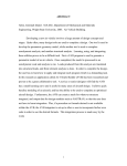
1
VTT-R-00651-14 RESEARCH REPORT SIMPRO / VTT Task 2.3 Optimisation of a particle damper with DEM Authors: Paul Klinge Confidentiality: Public (confidential until August 31. 2015) RESEARCH REPORT VTT-R-00651-14 1 (17) Report’s title SIMPRO/VTT Task 2.3 - Optimisation of a particle damper with DEM Customer, contact person, address Order reference Tekes, Matti Säynätjoki Kyllikinportti 2, P.O. Box 69, FI-00101 Helsinki, FINLAND Tekes: 40204/12 Project name Project number/Short name Structure optimisation using Discrete Element Method 78634/SIMPRO Author(s) Pages Paul Klinge 18/ Keywords Report identification code particle damper, continuous excitation, DEM, optimisation, optimization, high-performance computing VTT-R-00651-14 Summary The idea of this study was to show that designing a particle damper using optimisation is feasible with the computational power of current parallel computers and DEM tools. It was shown that the concept works. The Parallel Direct Search optimisation method was able to find the optimal configuration for the particle damper. Also the straight forward parameter study proved to be a viable option. On the other hand it was found that the DEM tools need more development and that the DEM simulation is slower than expected. Also in this study a 5 to 10 times saving for the simulation time was found by showing that it is not necessary to simulate until the transient peeks due to the start are settled out. Confidentiality Public (confidential until August 31. 2015) Espoo 31.1.2014 Written by Reviewed by Accepted by Paul Klinge Principal Scientist Kari Tammi Research Professor Juha Virtanen Team Manager VTT’s contact address Distribution (customer and VTT) Tekes/Matti Säynätjoki, 1 copy VTT/archive, 1 copy The use of the name of the VTT Technical Research Centre of Finland (VTT) in advertising or publication in part of this report is only permissible with written authorisation from the VTT Technical Research Centre of Finland. RESEARCH REPORT VTT-R-00651-14 2 (17) Contents Contents ................................................................................................................................. 2 1. Introduction ....................................................................................................................... 3 2. Pre-study of open source DEM codes ............................................................................... 3 2.1 Pre-study conclusions ............................................................................................... 3 3. Work plan ......................................................................................................................... 4 3.1 Installation of LIGGGHTS ......................................................................................... 4 3.2 LIGGGHTS vs. ABAQUS .......................................................................................... 4 4. ABAQUS DEM .................................................................................................................. 5 5. Open source optimisation code DAKOTA ......................................................................... 6 6. Initial configuration for the particle damper ........................................................................ 7 7. Experiences with optimisation ........................................................................................... 8 8. Results............................................................................................................................ 12 8.1 Speeding up the simulation time ............................................................................. 14 9. Discussion ...................................................................................................................... 16 10. Summary ........................................................................................................................ 17 References ........................................................................................................................... 17 RESEARCH REPORT VTT-R-00651-14 3 (17) 1. Introduction Tuned mass dampers (TMD) are simple devices that are widely used in engineering to reduce the amplitude of mechanical vibration of structures and devices. Designing an optimal TMD is not difficult, because there are formulas for optimal mass ratio and optimal damping ratio. A TMD attenuates vibration only in a narrow frequency range. A lot of TMDs with an active control method has been developed to get attenuation in a wider frequency range. Another simple device for reducing mechanical vibration is a particle damper. Particle dampers are composed of a cavity that contains the particles (for instance sand, lead beads, ball bearings etc.). The principle behind particle damping is the removal of vibratory energy through losses that occur during impact of granular particles with each other and the cavity walls. Particle dampers are highly nonlinear devices, because their damping comes from different loss mechanisms, including friction and momentum exchange of a large number of particles. This is also why they can attenuate a wider frequency range. There are some rules-of-thumb for designing a particle damper. These rules are based on measured results from experimental testing and simplified analytical models. By [Fowler & al 2001] the design process include: (1) determine characteristics of the undamped system; (2) determine appropriateness of particle dampers; (3) select preliminary particle damper configuration; (4) determine characteristics of the undamped system with adjusted mass; (5) evaluate damper effectiveness using the particle damper simulation technique; (6) as necessary, modify damper configuration from Step 3 and repeat Steps 4 and 5; and, (7) verify chosen design experimentally. The idea of this study is to replace the repetitive step (6) with optimisation. The author thinks that the computational power of current parallel super computers, the development of discrete element method tools (DEM) as well as the development of optimisation tools make it a feasible option. 2. Pre-study of open source DEM codes The pre-study was done by searching articles and conference presentations from the last 10 years. The most interesting looking texts by title were opened and read more or less thoroughly depending on the content. When enough understanding of the methods had accumulated, the net was searched for software. The results of the pre-study are summarized in the Appendix. 2.1 Pre-study conclusions In the pre-study DEM software LIGGGHTS (http://cfdem.dcs-computing.com/) (built on LAMMPS) looked the most promising for the task considering: user friendliness, capabilities, and parallelisation. LAMMPS (http://lammps.sandia.gov/) has been developed by Sandia National Laboratories, the same organization that have developed the intended optimisation software DAKOTA (http://dakota.sandia.gov/). In the pre-study many articles of designing a particle damper was found. None was close to our case study: the diesel aggregate. Anyway the conclusion is that the designing must be done case by case. RESEARCH REPORT VTT-R-00651-14 4 (17) 3. Work plan The following task list was achieved based on the pre-study. 1) Installation of LIGGGHTS and familiarizing with it 2) Finding the initial configuration for the particle damper 3) Setting up the optimisation loop and optimisation runs for VTT genset The main damping mechanisms of a particle damper are impact and friction. How the damper behaves depends on many parameters: size, shape, and number of cavities size, shape, material, and number of particles type and amplitude of excitation/vibration DEM solvers calculate most effectively with spherical particles, so it made sense to limit this study to spherical particles and use just one material. At first 'only' the size and the shape of the cavity and the number of particles are used as the optimisation parameters. Optimisation will be done with open source software DAKOTA. 3.1 Installation of LIGGGHTS There were some problems when installing LIGGGHTS. After reinstalling libraries also LIGGGHTS installed. However, the granular package did not work, though some other packages did. Incompatible versions of the main program and the granular package was suspected. There was also confusion, because the provided granular example ended with error. There had been two changes in the input file format during the previous 6 months. First an old version was found that worked with the example and finally also the latest version installed properly and some self-made examples were run. 3.2 LIGGGHTS vs. ABAQUS During the summer a new version of Abaqus had been released, ABAQUS 6.13-1 (http://www.3ds.com/products-services/simulia/portfolio/abaqus/). It included new discrete particle elements. It meant readymade concurrent FEM-DEM solver with familiar pre- and post-processing for the author. LIGGGHTS project is working to include FEM with their code, but as yet only FEM solution for temperature is supported. However, there is a one man project that has connected LIGGGHTS and an open source structural FEM code Code-Aster (http://coolsimulations.wordpress.com/tag/liggghts/). It was considered that using ABAQUS would save a lot of time and effort for the project and it was decided to continue the project with ABAQUS. RESEARCH REPORT VTT-R-00651-14 5 (17) 4. ABAQUS DEM The name Discrete Element Method (DEM) is used at least for three different numerical methods for computing the motion of a large number of particles. The basic DEM that is used in this study uses Newton mechanics to calculate the motion of each particle including its rotation. Of course, also the contact forces, including friction, have to be solved. 𝑛𝑖 𝒎𝑖 𝒓̈ 𝑖 = ∑ 𝑭𝑖𝑗 + 𝒃𝑖 𝑗=1 𝑛𝑖 𝑱𝑖 𝜽̈𝑖 = ∑ 𝒒𝑖𝑗 × 𝑭𝑖𝑗 + 𝑲𝑖 𝑗=1 DEM is computationally intensive when a large number of particles is used. However, it suits ideally for parallel computing. The method was originally developed by Cundall in 1971 for problems in rock mechanics. ABAQUSes DEM model is a basic one. Each DEM particle is modeled with a single-node element (type PD3D). The elements are rigid spheres with uniform density and user specified radii. It is possible to use different sized particles. It is also possible to model grains of complex shapes by clustering spherical particles together. Though the DEM particles are rigid there is still compliance between them (see Figure 1). For every kind of contact an equivalent contact force versus penetration curve is defined. It can simply linear spring force or a complicated function defined by a table. Typically the Hertz contact solution is used. Of course, there are also contacts between DEM particles and finite element surfaces. Figure 1. The equivalent compliance of DEM particles. RESEARCH REPORT VTT-R-00651-14 6 (17) The particles have displacement and rotational degrees of freedom. There is friction between particles, but also contact damping based on relative velocities of contacting particles. There is also an extra damping (option alpha) that acts on translational and rotational velocities of individual particles with respect to “ground”. Usually ABAQUS/Explicit automatically controls the time increment size. However, a stable time increment cannot be computed for the DEM particles, because they are rigid. The user must specify a fixed time increment size for DEM analyses. The time increment for the analysis must be small enough to avoid numerical instabilities. Unfortunately ABAQUSes current version's DEM solver does not utilize parallelisation. Simulia has promised that parallel DEM solver will be in the new ABAQUS version 6.14-1 that will be published this summer. 5. Open source optimisation code DAKOTA The DAKOTA (Design Analysis Kit for Optimisation and Terascale Applications) toolkit provides a flexible interface between solver codes and iterative systems analysis methods. DAKOTA contains algorithms for optimisation with gradient-based and non-gradient-based methods; uncertainty quantification with sampling, reliability, stochastic expansion, and epistemic methods; parameter estimation with nonlinear least squares methods; and sensitivity/variance analysis with design of experiments and parameter study methods. These capabilities may be used on their own or as components within advanced strategies such as hybrid optimisation, surrogate-based optimisation, mixed integer nonlinear programming, or optimisation under uncertainty. A nice feature of DAKOTA is that it manages itself the parallel runs. That includes a working restart system. DAKOTA runs are controlled with a clear text input file and the User's manual includes many examples of the input file. DAKOTA communicates with the solver via text files. DAKOTA writes a file that contains new values for the parameters and their names plus some other information. With DAKOTA installation comes a Perl script 'deprepro' that replaces the parameter name strings in the solver's template input file with the new numerical values. The user has to take care of reading the results from solver's output files or database and write 'the object function values' into a file in correct order. For this study a Python program was written that reads the velocity time series of the damped mass from the ABAQUS output database, calculates average response of the last seconds of the ABAQUS run, and writes the average amplitude into a file for DAKOTA. DAKOTA needs also a shell script to launch the solver. The script contains basically only three lines: 1. to run deprepro, 2. to launch the solver, and 3. to run the program/script that reads results and writes them into the file for DAKOTA. RESEARCH REPORT VTT-R-00651-14 7 (17) 6. Initial configuration for the particle damper At first ABAQUS DEM was tested by modifying the example model presented in the manual. Then a simple structural model with a particle damper was created using the spherical particles of the ABAQUS example model. The structural part of the model was the most simple, just a spring and a mass. A rigid spherical cavity made of shell elements was attached to the mass. A mass of 1 ton, resonance frequency of 20 Hz, and 1000 N harmonic excitation force was considered realistic enough 'industrial case' to begin with. There are many parameters that define the behaviour of a particle damper. After the pre-study it was decided that only the size and the shape of the cavity, and the number of particles are used as the optimisation parameters. The shape of cavity was decided to be a cylinder with hemispherical ends. Only 2 parameters, the length of the cylindrical part, and the common radius of the cylinder and the ends are needed to define it (see Figure 2). Figure 2. The effect of the length of the cylindrical part to the shape of the cavity Test runs with the 1 ton mass showed that there were not enough particles. The mass was reduced until clear attenuation and impacting behaviour appeared so that the main modes, friction and impact, of a particle damper were included. The mass went down to 150 kg. Figure 3. The particle damper in impact mode RESEARCH REPORT VTT-R-00651-14 8 (17) After settling to the first model with the spherical particles of the ABAQUS example, the material for the spheres was changed to steel. Steel turned out to be much more difficult material for the solver. It required almost 2 orders of magnitude shorter time increment and accordingly longer simulation times. It was decide to use the example values which were for limestone, E = 4.0E+04 N/mm2 and ν = 0.25. The density of steel ρ = 7.85E-09 ton/mm3 was still used. The example friction coefficient between the spheres 0.35 was used. In ABAQUS there is also option alpha that is used to add mass proportional damping to the spheres. The manual says: "A small amount of mass proportional damping is beneficial in reducing the noise in the solution generated by numerous opening and closing contact conditions". The example value of alpha = 7.0 was used. The ranges for the parameters were decided by test runs. Number of spheres from 1000 to 10 000 was going to be tested, but it soon turned out that the simulation takes longer than expected. The range of spheres from 1000 to 3000 was used instead. It was still difficult to pack 3000 spheres of 6 mm diameter into the cavity so that it becomes somewhat overfull. It was succeeded by arranging the spheres into a rectangular cuboid (Figure 4) so that they are initially somewhat compressed. The range from 80 to 120 mm for the radius was found and 1 to 100 mm for the cylindrical part was considered suitable. Figure 4. A configuration of the particle damper at the beginning and at the end of the settling step. 7. Experiences with optimisation The results of a simulation are time series. To find the optimal particle damper a time independent 'objective function' is needed. The idea was to simulate the particle damper long enough time so that the transient peaks due to the starting have settled down and then calculate the average amplitude of the remaining vibration for the damped mass. The average velocity amplitude of the last 2.5 seconds was considered to give a good 'objective function' value. Initially after some test runs the simulation time of just 5 seconds seemed to be long enough. RESEARCH REPORT VTT-R-00651-14 9 (17) Many optimisation algorithms have been implemented in DAKOTA. Only a couple of quite complicated methods can, in principle, be used to optimize a particle damper. This is because the number of particles is a discrete variable. However, there are many simple methods to be used with continuous variables. That is why the number of particles was transformed to pseudo-continuous variable by rounding the real number provided by DAKOTA to a whole number for ABAQUS. First the NL2SOL algorithm was tested. It is a secant-based least-squares algorithm. It adaptively chooses between the Gauss-Newton Hessian approximation and the same approximation with a correction term from a secant update. NL2SOL is said to be more robust than conventional Gauss-Newton approaches. Robust or not but NL2SOL did not work. It never advanced far from the starting point and found 'the optimum' near it though the starting point was varied. Increasing the step size did not work either. It was concluded that the solution had not settled enough in the 5 seconds simulation time that was used then. The simulation time was doubled to 10 seconds, but it did not help. It turned out that even after 30 seconds there are some kind of fluctuations in the solution (Figure 5). This may explain the failure of the algorithm. Figure 5. Fluctuations in the simulated vibration velocity RESEARCH REPORT VTT-R-00651-14 10 (17) To circumvent the complications caused by the fluctuations a global algorithm that does not use numerical derivatives was searched. DIRECT (DIvision of RECTangles) [Finkel 2003] was selected because of its simplicity. DIRECT is a global sampling algorithm that divides the search domain into smaller domains and uses points that it has calculated to decide where to search next. DAKOTA includes two implementations of DIRECT. The simpler, ncsu_direct, was tested. The optimisation run ended because the ABAQUS run ended with error. A second test was run with a slightly modified search domain but the result was the same. The search domain had been determined by test runs. It had been checked that the ABAQUS solver does not fail at the vertexes of the domain. Of course, it does not guarantee that there are no points in the domain where the solver fails. ABAQUS DEM solver had proved to be quite sensitive to the rotation of the spheres. One too large rotation of one sphere during one time increment stops the simulation in error. Figure 6. The principle of DIRECT algorithm [Sahinidis 2010] RESEARCH REPORT VTT-R-00651-14 11 (17) Next a direct pattern search algorithm, PDS (Parallel Direct Search) [Dennis & Torczon 1994] was tested. It also is a global algorithm and does not use numerical derivatives. The principle of a pattern search algorithm is presented in Figure 7. Despite of the name of the algorithm the implementation in DAKOTA is serial. This means real long optimisation times. That is why it was decided to use only 2 parameters (L and R) and fix the number of spheres to 3000. With 2 parameters PDS uses 2*16 = 32 points per step. PDS worked fine. It found practically the optimum with 7 steps after calculating 227 points. However, the algorithm did not stop, but continued to try to refine the result. After two extra steps the run was stopped. Figure 7. The principle of pattern search algorithms [Sahinidis 2010] RESEARCH REPORT VTT-R-00651-14 12 (17) 8. Results The Parallel Direct Search algorithm found the most effective configuration for the particle damper, the point in the search domain where the settled amplitude of the damped mass is the smallest in the search domain. The optimum configuration for the particle damper is: the length of the cylindrical part = 1.7 mm, the common radius of the cylinder and the ends = 80.3 mm, and there are 3000 spheres in the cavity. If the search had not been stopped a result even closer to the optimum at the vertex (1 mm, 80 mm, 3000 pcs) of the search domain would have been found. The minimum simulated velocity amplitude was 333 mm/s. The velocity as a function of time is shown in Figure 8. The obtained optimum configuration is not the expected “rattle” solution. It is also not a realistic one, because the spheres are in a highly compressed state inside the cavity. A parameter study was run to have a better understanding of the situation. The distribution of the velocity amplitude of the damped mass with 1000, 2000, and 3000 spheres is shown in Figure 9. The response of the particle damper looks like a hill and a plateau. All the points on the plateau are relatively optimal, but they cannot be accepted because of the high compression of the spheres. A more realistic optimum is where the compression starts along the curve where the colour changes to dark blue. There the velocity amplitude is about 500 mm/s which is equivalent to about 5 % damping ratio with 14 % extra mass. The compression of the spheres should be limited using a constraint equation in the optimisation. Figure 8. The simulated velocity of the damped mass of 150 kg at the optimum RESEARCH REPORT VTT-R-00651-14 13 (17) Figure 9. Velocity amplitude of the damped mass of 150 kg with 1000, 2000, and 3000 spheres in the damper's cavity RESEARCH REPORT VTT-R-00651-14 14 (17) 8.1 Speeding up the simulation time It takes on average about 3 hours in CPU time and in real time to simulate 10 seconds for one particle damper configuration with ABAQUS and the longest simulation run took about 11 hours. This is because in this ABAQUS version the DEM solver is serial. A 10 seconds simulation time is needed for the response to settle. Figure 5 and Figure 8 show typical behaviours of the particle damper. It seems that the first 1.5-2.5 seconds would give about the same average the velocity amplitude as the last 2.5 seconds. The 1000 kg mass example was discarded in the beginning because it did not settle fast enough. The velocity with 1000 kg was calculated in the same optimal vertex as above (see Figure 10). It indicates that the settling would take about 6 times longer simulation time. However, if one trusts to the above observation simulating only about 10 seconds should be enough. A sparse parameter study was run and the result is shown in Figure 11. It is very similar to the result with the 150 kg. So, the shorter simulation time, about 3-4 times the time it takes the response to develop fully, seems to be enough. Here the more realistic optimum velocity amplitude is about 1000 mm/s which is equivalent to about 0.4 % damping ratio with only 2 % extra mass. Figure 10. The simulated velocity of the damped mass of 1000 kg at the optimum RESEARCH REPORT VTT-R-00651-14 15 (17) Figure 11. Velocity amplitude of the damped mass of 1000 kg with 1000, 1800, and 3000 spheres in the damper's cavity RESEARCH REPORT VTT-R-00651-14 16 (17) 9. Discussion The idea of this study was to show that designing a particle damper using optimisation is feasible with the computational power of current parallel computers and DEM tools. That goal was attained, but the tools are not yet quite ready. The first experience was that the DEM simulation takes much more CPU time than the prestudy indicated. It turned out that DEM simulation is much faster when the spheres touch each other lightly whereas when the spheres are compressed against each other the simulation takes more time. This probably due to the nonlinear Hertz contact forces. ABAQUS’es DEM solver was sensitive to the stiffness of the material of the spheres. A stiffer material needs much shorter time increment than a softer material. In this case two orders of magnitude shorter increment for the 5 times stiffer material. Naturally the collision of two stiff spheres is faster than with soft spheres. If this is a direct consequence of physics that cannot be helped with clever programming, the demand for computer power is much higher than expected for steel spheres. The obtained optimal configuration for the particle damper was not what was expected. It is natural that the optimal configuration includes as many spheres as possible. Of course, a friction based damper can be the optimal configuration. However, in this case it may be due to the mixed limestone-steel material that was used in this study because of the above mentioned sensitivity. It was a disappointment that the ABAQUS’es DEM solver did not utilize parallelization. Simulia has promised that a parallel DEM solver will be in the next ABAQUS version. But it was not available now and the parallel simulation could not be tested. However, a simple assessment can be done. Below (Table 1) three parameters has been used as in this study. Number of solution steps for the numerical derivative based solver and DIRECT are 'educated guesses'. It was assumed that the parallel DEM solver can efficiently use 10 CPUs. The assessment shows that without a parallel DEM solver only PDS and a parameter study are feasible. However, parallel DEM solver evens out the differences and all algorithms seem feasible. Table 1. Relative optimisation times for different kind of algorithms Real time Max with 100 parallel No Real time Real time CPU and simulatio solution Real time with 10 with 100 parallel ns steps = CPUh CPUs CPUs simulation No parameters = 3 Numerical derivatives 3 50 200 100 100 10 DIRECT 1 100 100 100 100 10 Parallel Direct Search 48 10 480 48 10 5 Parameter study 500 1 500 50 5 5 RESEARCH REPORT VTT-R-00651-14 17 (17) 10. Summary The idea of this study was to show that designing a particle damper using optimisation is feasible with the computational power of current parallel computers and DEM tools. It was shown that the concept works. The Parallel Direct Search optimisation method was able to find the optimal configuration for the particle damper. Also the straight forward parameter study proved to be a viable option. On the other hand it was found that the DEM tools need more development and that the DEM simulation is slower than expected. Also in this study a 5 to 10 times saving for the simulation time was found by showing that it is not necessary to simulate until the transient peeks due to the start are settled out. Not all the goals of the project were met. The particle damper was studied with one single frequency and with the simplest possible structural model, a mass and a spring. Hopefully the particle damper and optimisation can be tested soon with an industrial case with several excitation frequencies and resonances with the parallel DEM solver. References Dennis, J.E. & Torczon, V.J. Derivative-free pattern search methods for multidisciplinary design problems. In Proc. 5th AIAA/USAF/NASA/ISSMO Symposium on Multidisciplinary Analysis and Optimization, AIAA-94-4349, p. 922–932, Panama City, FL, September 7–9 1994. Finkel, D.E. DIRECT Optimization Algorithm User Guide. Center for Research in Scientific Computation North Carolina State University, Raleigh, NC, 2003. Fowler, B.L., Flint, E.M., Olson, S.E., Design Methodology for Particle Damping, SPIE on Smart Structures and Materials, Newport Beach, CA, 2001. Paper # 4331-20 Sahinidis, N. Derivative-free optimisation. 2010 http://egon.cheme.cmu.edu/ewocp/docs/SahinidisEWO_DFO2010.pdf