1
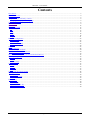
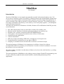
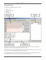
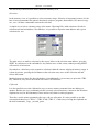
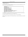
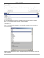
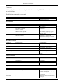
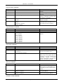
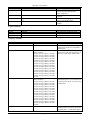
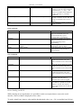
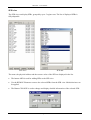
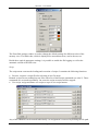
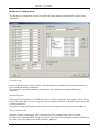
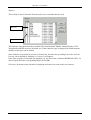
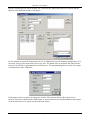
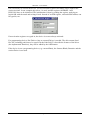
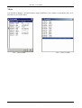
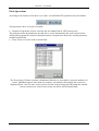
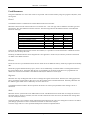
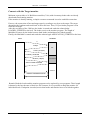
MiniMon User Manual (c) 1998-2004 by Christian Perschl Minimon - User Manual Contents Introduction......................................................................................................................................................................... 3 Frontend Overview ............................................................................................................................................................. 4 Memory View ..................................................................................................................................................................... 6 Representation of memory contents................................................................................................................................ 6 Changing the displayed memory range........................................................................................................................... 6 Terminal/Status view .......................................................................................................................................................... 8 Command line..................................................................................................................................................................... 9 SFR view........................................................................................................................................................................... 15 Menue and Toolbar........................................................................................................................................................... 17 File ................................................................................................................................................................................ 17 Edit................................................................................................................................................................................ 17 View.............................................................................................................................................................................. 17 Target............................................................................................................................................................................ 18 Settings ......................................................................................................................................................................... 18 Script............................................................................................................................................................................. 21 Hardware Configuration ................................................................................................................................................... 23 Controller type .............................................................................................................................................................. 23 Initialize Register .......................................................................................................................................................... 23 Initial command calls.................................................................................................................................................... 23 Memory......................................................................................................................................................................... 24 Views ................................................................................................................................................................................ 27 Flash Operations ............................................................................................................................................................... 28 Shell and Script Commands.............................................................................................................................................. 30 MiniMon Communication Protocol .................................................................................................................................. 34 Execute SWRESET .................................................................................................................................................. 34 Monitor Extension Interface for User Subroutines/Drivers .............................................................................................. 35 Memory Management....................................................................................................................................................... 36 Monitor ......................................................................................................................................................................... 36 Driver ............................................................................................................................................................................ 36 Data Exchange .............................................................................................................................................................. 36 Used Resources.................................................................................................................................................................37 Kernel ........................................................................................................................................................................... 37 Drivers .......................................................................................................................................................................... 37 Registers........................................................................................................................................................................ 37 Stack ............................................................................................................................................................................. 37 Connect with the Target monitor ...................................................................................................................................... 38 The target monitor ............................................................................................................................................................ 39 Initialisation .................................................................................................................................................................. 39 Start a user program ...................................................................................................................................................... 39 Drivers .......................................................................................................................................................................... 39 External files ..................................................................................................................................................................... 40 Preferences:................................................................................................................................................................... 40 Definition files: ............................................................................................................................................................. 40 Register Definition file: ................................................................................................................................................ 40 Memory Definition file: ................................................................................................................................................ 40 Page 2/41 Minimon - User Manual MiniMon User Manual Introduction The idea of MiniMon is a tiny monitor program that is started via bootstrap loader to any C16x XC16x micro controller system. The monitor is initially located in the internal RAM, and therefore it works on any target hardware (bootstrap loader required), especially single chip applications. It can be relocated to any address (internal or external memory) at any time. The monitor has only a few simple commands (read memory, write memory, write word, jump segment...), all intelligence is provided by the front-end. The front-end, which runs on Windows 95/98/Me, Windows NT and Windows 2000/XP, provides several functions: Hex editor functionality: load, save Intel Hex or binary files, modify, print Memory transfer functions: download, upload and compare any memory area Program, erase, (un)lock, (un)protect Flash/OTP/EEPROM areas View options: view memory as assembler code, 16 Bit or 32 Bit values Load and start user applications Call user subroutines SFR view: display and change SFR values, arranged in several register sets Terminal function: send and receive any data via RS232 Scripting: A command can be selected either via menu or executed in scripts The main advantages of Minimon is its compactness, its ability to locate free (without recompile/link) and its easy memory access functions. It works on a kind of „hardware“ level and has (nearly) no access restrictions. The front-end has a terminal view that shows all data received over the serial interface (e.g. debug outputs via printf). The main applications of MiniMon are hex editing, memory dumps, Flash/OTP programming, tests of micro controller peripherals and external hardware, downloading and starting of user applications. Page 3/41 Minimon - User Manual Frontend Overview The front-end of MiniMon consists of 4 parts: Memory view Terminal/Status view SFR view Command line The memory view shows the current memory contents as hex values. Of course it is possible to change the values. The memory area has an ASCII-section, too. The terminal/status view is used by the front-end to output status and error messages. It is also used to view received serial data while running an user application. The command line (below the terminal/status window) is used to give commands to MiniMon (as text). It can be used to send any bytes or text strings (like a terminal), too. Page 4/41 Minimon - User Manual The SFR view is used to display SFR register contents and to change them. SFR Registers can be arranged in up to 5 independent Register sets, where 1 set is displayed at a time. Page 5/41 Minimon - User Manual Memory View Representation of memory contents It is distinguished between used and unused memory areas. An unused memory byte is viewed as a blank character (initially a point, can be set by user). Used bytes are displayed as hexadecimal 8 Bit values. Besides, the used memory areas can be distinguished further between valid and invalid data. Data that was just uploaded or (correct) downloaded is valid, changed values or loaded files are principally invalid, until they are downloaded or programmed. This means, the target memory area is NOT corresponding 1:1 to the displayed memory contents. This is caused by the fact that Flash or OTP memory areas can´t be written or changed transparent and instant. Valid data is displayed by black hex numbers, invalid data is displayed by red hex numbers (initial values, can be set by user). Changing the displayed memory range The memory view can display 256 bytes of the memory contents at a time. Initially, the memory values from address 000000 to 0000FF is displayed. If a file is loaded, the first used address is displayed. To scroll the memory within the current segment, the scroll bar right of the memory view can be used. To step through the segments, the aligned double arrows can be used. The second and recommended way to change the displayed memory range is to put the display start address directly into the white text field in the upper left corner of the memory view (Direct Address Input). Scrolling can be applied by the keys PgUp and PgDown, too. Changing the memory contents It is possible to change a memory value. Therefore it is necessary to click with the mouse into the according field and type in the value. To mark a selection as unread, the Del key is used Page 6/41 Minimon - User Manual The arrow keys can be used to move inside the memory view. Selections In the memory view, it is possible to select a memory range. Selection is important, because it’s the base of most commands like upload, download, compare, program, disassemble, fill, unread, copy, cut , save. All these commands concern the selection. A simple way to select a memory range is the menu: Choosing Edit / Add selection will ask for selection start and end address. Nevertheless, it is possible to input the start address and a given selection size, too: The other way is to make a selection by the cursor. Move to the selection start address, press the SHIFT key and move to the end address. Any further move of the cursor without pressing SHIFT will remove all selections. Nevertheless, a third way exists to make a selection within the current displayed memory range: it is done by mouse, pressing the left button at the selection start, move to the selection end and release the button. Multiselections are done like described above, but additionally it is necessary to press the CTRL key. Otherwise, any cursor movement will remove all selections. Clipboard It is also possible to use the clipboard to copy or move memory contents from one address to another. Besides, the copy command puts the currently selected memory contents to the Windows clipboard as text, for documentation issues and to reuse them in other programs. Therefore, use the menu commands edit-copy, edit-cut, edit-paste. It is also possible to use the conventional short-keys CTRL-C, CTRL-X and CTRL-V. A third way of using the clipboard are the shell commands _copy, _cut and _paste. Page 7/41 Minimon - User Manual Terminal/Status view The terminal/status view displays all MiniMon status and error messages (beginning with *). It also repeats all shell commands (beginning with >). After starting an user program, it displays all data received by the serial interface as hexadecimals or as ASCII Text (terminal display type can be changed by user). It is possible to select any text in the terminal view and to copy it to the clipboard. Double-clicking on an already executed command (leading ‚>‘) puts this command to the command line again. Page 8/41 Minimon - User Manual Command line The command line is used to input commands. It is an alternative way to the menu and toolbar giving instructions. Besides, it can be used to send serial data directly, too (e.g. to application). The last commands that were input to the command line are stored and available as command history. Use the list field to repeat a previously executed command. Command selector To see all usable shell/script commands, use the comfortable command selector by pressing the corresponding button. In the appearing command selector window, all valid commands are listed, with usage message and a short description. Page 9/41 Minimon - User Manual Commands Additionally, all commands can be displayed by the command _HELP. The commands are the same as used in scripts. The following commands are accepted: COMMAND _help PARAMETERS - DESCRIPTION displays help message in status/terminal view COMMAND _load PARAMETERS <filename> _save <filename>, <recordsize> optional, <format> optional <filename>, <address offset> optional DESCRIPTION loads Intel Hex file <Filename> into host memory saves selection into Intel hex file <Filename> File commands _binload _binsave loads binary file <Filename> into host memory, beginning at given address offset saves selection into binary file <Filename>, at fragmented multiselections fill space with fill char <filename>, <fill char> optional Hex Editor commands COMMAND _copy _cut _paste PARAMETERS <start address> _fillmemory <fill value> _clearmemory _randomfill - DESCRIPTION copies selection into clipboard cuts selection into clipboard pastes clipboard into memory, beginning at <start address> fills selection with byte or word value <fill value> mark selection bytes as unread Fills current selection with random values Selection commands COMMAND _addselection _clearselections _showselections PARAMETERS <start address>, <end address> - DESCRIPTION adds selection from start address to end address removes all selections lists the current selections and their range Target Connection commands COMMAND _connect PARAMETERS NOPROMPT optional _reconnect - _disconnect - DESCRIPTION connects to target, if parameter NOPROMPT is passed, no prompt window is displayed looks if monitor is ready; can be used to reconnect disconnects from target and closes comm port Page 10/41 Minimon - User Manual Target Transfer commands COMMAND _download PARAMETERS - _upload - _compare <filename> optional _mov <address>, <value> <address 1>, <data 1>, <address 2> optional, <data2> optional, ..... _movseq DESCRIPTION downloads selection into target memory reads from target memory into selection compares selection with target memory, if filename is passed, results are written in <Filename> writes word <Value> to memory at address or to SFR Several memory writes of independent data and addresses are done within one write sequence Target Execution commands COMMAND _srst _jmp _call PARAMETERS <start address> <start address>, <R8> optional, <R9> optional, <R10> optional, <R11> optional, <R12> optional, <R13> optional, <R14> optional, <R15> optional DESCRIPTION executes Software Reset jumps to <Start Address> calls driver/user subroutine at <Start address> Target Misc commands COMMAND _einit _movemonitor _setprotection _pllcon PARAMETERS <start address> <security level>, <password>, <new password> optional <pllcon value> DESCRIPTION executes the EINIT command moves monitor to <Start address> Enables or disables system register protection (XC family only) Sets the register PLLCON (XC family only). The register PLLCON can not be set by the standard write commands, because it possibly changes the baudrate. Therefore, this separate command is provided. SFR View commands COMMAND _refreshsfr PARAMETERS ON|OFF optional _addsfr <SFR name>, <SFR set> optional <SFR name>, <SFR set> optional _removesfr DESCRIPTION can be used either to refresh values of SFR registers in current SFR set, or to generally activate or deactivate the refresh. adds SFR register to current SFR set or to given SFR set removes SFR register from current SFR set or from given SFR set Terminal / Comm commands Page 11/41 Minimon - User Manual COMMAND _send PARAMETERS <string>|:<hex values> _sendfile <filename> _setp <signal>, 0|1 <baudrate> _setbaudrate DESCRIPTION sends the <send string> to RS232. Send string can be hexadecimal values, leaded by a : sends the binary file <filename> 1:1 to RS232 sets the signal to logical 0 or 1. Signal can be DTR or RTS changes the current interface baudrate Logfile commands COMMAND _logfile _setlogfile _writelogfile PARAMETERS ON|OFF <filename> <string> DESCRIPTION turns the log file writing on or off changes the log file to <filename> writes string to log file Scripting commands COMMAND _delay _pause _message _cmessage _assign PARAMETERS <delay time> - DESCRIPTION delays for <delay time> seconds pauses script execution and displays message box. Waits for confirmation (Button OK) <string>|<SFR>|<variable>,<string>|< pauses script execution and displays SFR>|<variable> message box with messagestrings1-16. optional,<string>|<SFR>|<variable> Waits for confirmation (Button OK) optional,<string>|<SFR>|<variable> optional,<string>|<SFR>|<variable> optional,<string>|<SFR>|<variable> optional,<string>|<SFR>|<variable> optional,<string>|<SFR>|<variable> optional,<string>|<SFR>|<variable> optional,<string>|<SFR>|<variable> optional,<string>|<SFR>|<variable> optional,<string>|<SFR>|<variable> optional,<string>|<SFR>|<variable> optional,<string>|<SFR>|<variable> optional,<string>|<SFR>|<variable> optional,<string>|<SFR>|<variable> optional <string>|<SFR>|<variable>,<string>|< displays message box with SFR>|<variable> messagestring1-16, but continues with optional,<string>|<SFR>|<variable> script execution. Does not wait for any optional,<string>|<SFR>|<variable> confirmation optional,<string>|<SFR>|<variable> optional,<string>|<SFR>|<variable> optional,<string>|<SFR>|<variable> optional,<string>|<SFR>|<variable> optional,<string>|<SFR>|<variable> optional,<string>|<SFR>|<variable> optional,<string>|<SFR>|<variable> optional,<string>|<SFR>|<variable> optional,<string>|<SFR>|<variable> optional,<string>|<SFR>|<variable> optional,<string>|<SFR>|<variable> optional,<string>|<SFR>|<variable> optional <expression> assigns a variable an expression. Valid variable names are %0 to %99. On the right side of the = either SFR registers Page 12/41 Minimon - User Manual _executescript <filename>,<continue> optional _quit - or variables can be assigned. It is possible to execute simple arithmetic operations like +,-,*, /,&,|, ~. The value of a variable can be displayed via the _message or _cmessage command Executes the subscript <filename>. If the flag <continue> is set to ON, the script is continued even if an error occurs Exits Minimon. If used, it is the last script executed. Flash commands COMMAND _iprogram PARAMETERS - _program - _erase <device name>, <sector> <device name> _status DESCRIPTION Programs the current selection into flash. The used flash sectors are erased automatically by this command before programming. Programs the current selection into flash. The used flash sectors have to be erased manually before programming. Erases the given <Sector> of the Flash Device <Device name> Reads and displays the relevant flash status registers of the flash device <Device name> View commands COMMAND _viewword PARAMETERS - _viewlong - _viewbyte - _viewassembler - _viewsfrs <SFR set> optional DESCRIPTION Views the current selection as 16 Bit hexadecimal numbers and writes them to Terminal view as well as log file Views the current selection as 32 bit hexadecimal numbers and writes them to Terminal view as well as log file Views the current selection as 8 bit hexadecimal numbers and writes them to Terminal view as well as log file Views the current selection as assembler code and writes to Terminal view as well as log file Views all SFRs of a given SFR set. If no SFR set is passed, the current SFR set is viewed. The output is done to the terminal view as well as the log file. Direct Sending via RS232 While running an user application, it is possible to make user inputs that are sent to the serial interface. Received data is displayed as hex values. To send a single byte, input a colon and the hexadecimal value. (e.g. „:34“ to send the byte 34 hex). Page 13/41 Minimon - User Manual To send an ASCII string, just input the string. All inputs (commands, hex bytes or strings) have to be terminated by pressing the RETURN key. Page 14/41 Minimon - User Manual SFR view The SFR view can display SFRs, grouped by up to 5 register sets. The list of displayed SFRs is fully adaptable. SFR View SFR Add The name, the physical address and the current value of the SFR are displayed in the list. The button ADD is used for adding SFRs to the SFR view. Use the REMOVE button to remove the selected SFRs from the SFR view. Multiselections can be applied. The Button CHANGE is used to change and display detailed information of the selected SFR: Page 15/41 Minimon - User Manual The upper text field contains the hexadecimal value. Below, all bits and bitfields are displayed as binary values and can be changed either by double-click or directly by typing in the binary value. Of course, each SFR can be displayed in one register set just one time, but the same SFR can be displayed in different register sets. The current provided SFRs are dependent of the selected micro controller type (see 8.) Page 16/41 Minimon - User Manual Menue and Toolbar The menu provides one alternative way to the command line to execute commands. The most common commands are part of the toolbar, too. File The File Menu contains all file transfer commands like loading and saving as well as the printing function. Load Intel Hex: Loads an Intel Hex File into the Hex editor. Save As Intel Hex: Saves current Selection to an Intel Hex file. Alternatively it is possible to input a memory range directly (start and end address). It is possible to change the output format, like 20 bit or 32 bit Intel Hex, and the record length in bytes. Load Binary File: Load a Binary file into the Hex editor. The start address offset can be set freely. Save Binary File: Saves the current selection into a binary file. At multi-selections, the space between selections is filled up with a user-defined fill character if needed. Print: Prints the current selection as hex (similar to the memory view), assembler code or ASCII-Text. Load preferences: Overrides the current Minimon settings by selecting and loading a different .ini – File. Save preferences: Saves the current Minimon settings into preferences (.ini) file Load SFR register set: Loads a SFR register set file (.mrs) into current selection. Save SFR register set: Saves the currently displayed SFR set into a register set file (.mrs). Edit The Edit Menu provides clipboard, selection and fill capabilities. Copy: copies the (first) selection into an internal clipboard buffer (not to the system clipboard !) Cut: copies the (first) selection into an internal clipboard buffer and marks selection as unread Paste: pastes the clipboard contents into memory, beginning at the cursor position Remark: Only one closed memory range can be put to the clipboard. If multiple ranges are selected, only the first selection will be applied. Add Selection: adds a selection, given by start address or end address. Applied several times, mullet-selections are possible (see also 1.3.3) Clear all Selections: all selections will be removed, the memory contents are left unchanged. Fill Memory: fills the current selection with a constant value (given as hexadecimal number) Random Fill: fills the current selection with random values Clear Memory: marks all bytes in the current selection as unused View The View Menu provide several alternate display options for the current memory selection: Word: Displays the current selected memory contents as 16 Bit values. Page 17/41 Minimon - User Manual Long: Displays the current selected memory contents as 32 Bit values. Disassemble: Displays current selection as assembler code. Target The target menu contains all commands that concern the target hardware. Configuration: here the hardware (target) configuration is done. See 8. Connect: connects to target and executes all initialisation commands, according to hardware configuration Reconnect: reconnect to an already running monitor. Disconnect: disconnects the Minimon front-end from the kernel and closes the Comm port. Display Reset Configuration: Displays reset configuration, which was read at the last target connection Download: loads contents of current selection into target memory Upload: loads target memory into selection Compare: compares target memory with selection (e.g. previous loaded file) Relocate Monitor: MiniMon will be relocated to given start address. This is done by copying itself and jumping to new MiniMon start address. Remark: the old and the new monitor locations must not overlap. Settings This menu concerns the serial interface. Interface: Calls the dialog window to change the comm interface parameters. Changing the values before connection, only the Host settings will be applied (the bootstrap loader automatically detects baudrate at connection time) Changing the settings while being connected to the target will change both the host settings and the MiniMon settings (especially the baudrate). Page 18/41 Minimon - User Manual K-LINE is a single wire interface type. For K-LINE, different loader and monitor files are needed and downloaded. The change of this feature requires a reconnect. The check connection feature is used to periodically check the connection between the kernel and the frontend. If the connection is lost, this is shown in the status bar of the Minimon main window. If the check connection feature is used and a hardware reset is done while beeing connected, a second hardware reset is neccessary. While the Value for Timeout can occur during normal communication, the connection timeout occurs only during connection. The connection start by sending the Zero-Byte can be repeated, the relevant parameter is the Connect-Retry value. Terminal: Sets the output format for received data in the terminal view. If hex mode is selected, any received Data (e.g. from the application) is displayed in the terminal view as 8 Bit hexadecimal values. If Text/ASCII mode is selected, received Data is displayed as ASCII text. Kernel: Administrate and activate different default and user kernels Minimon is delivered with 4 default kernels for C16x and XC16x each: Page 19/41 Minimon - User Manual Kernel description C16X_DEFAULT This is the default kernel for C16x controllers. It provides the standard features like writing and reading memory, calling subroutines/drivers, jump to user programs, software reset and einit This kernel is the K-Line variant of the C16x default kernel. It provides the same features as the default kernel, but with k-line interface communication. The full kernel for the C16x controllers provides additionally to the default features the movseq capability The autobaud full kernel for the C16x controllers provides the same features as the full kernel, but additionally with autobauding on the first connect. This kernel is thought for integration in user applications to automatically detect the baudrate. This is the default kernel for XC16x controllers. It provides the standard features like writing and reading memory, calling subroutines/drivers, jump to user programs, software reset and einit This kernel is the K-Line variant of the XC16x default kernel. It provides the same features as the default kernel, but with k-line interface communication. The full kernel for the XC16x controllers provides all default features plus the features movseq, asc0 to asc1 and setprotection The autobaud full kernel for the XC16x controllers provides the same features as the full kernel, but additionally with autobauding on the first connect. This kernel is thought for integration in user applications to automatically detect the baudrate. C16X_KLINE C16X_FULL C16X_AUTOBAUD_FULL XC16X_DEFAULT XC16X_KLINE XC16X_FULL XC16X_AUTOBAUD_FULL Start size address 00FA60 392 00FA60 394 00FA60 426 00FA60 490 E00024 392 E00024 394 E00024 586 E00024 658 Beside, it is possible to register and activate own user kernels in Minimon. Administration and Modification of Kernel registration is done in the kernel settings menue. Front-End: Change Front-End appearance settings Page 20/41 Minimon - User Manual The Front-End settings window is used to change the default settings for different colors of the memory view. The blank char, which is displayed for unused data areas, can be chosen, too. Beside these optical appearance settings, it is possible to enable the file logging as well as the automatic refresh of the SFR view. Script The script menu concerns the loading and execution of scripts. It contains the following functions: Execute: executes a script file after selecting it in a file menu. Remark: script files are nothing but text files with a list of shell/script commands (see also 5). These commands are executed sequentially. On errors the script execution will be stopped. User script: assign and name user scripts to up to 8 user script buttons Any of the 8 Buttons can be named individually. An assignment is removed by deleting the file path Page 21/41 Minimon - User Manual List of the last 16 used scripts: This provides a fast script re-calling functionality Script example: _connect _clearselections _addselection 10000,1ffff _upload _save u1.hex This script connects to the target, selects the range from 10000-1FFFF, uploads the contents into the front-end memory and saves it to the Intel Hex file u1.hex Page 22/41 Minimon - User Manual Hardware Configuration The Hardware Configuration is used to describe the target hardware and initialise registers after connection. Controller type Several Controller types can be selected. This information is needed by the front-end to know the correct SFR and memory definitions. The clock rate is needed for baudrate initialisation, if the baudrate is changed while being connected. Initialize Register This Section can contain up to 12 SFRs that can be set after connection. The registers can be chosen freely. The values they are set to are given in the according text fields. A marked register means that it will be initialized. Two generic register definitions can be used free for any register known by its physical address. Initial command calls Similar to register initialisation, after connection specific command calls can be executed. If marked, the command EINIT can be executed as final action of initialisation. Remark: EINIT can be called at any time later by the shell command _einit, too. Page 23/41 Minimon - User Manual Memory This section is used to describe all memory devices or modules that are used. Map List Activate List This includes chip internal memory modules like internal RAM, XRAM, internal Flash or OTP. Xperipherals and SFR areas are included, too. If the controller type is changed, all default memory modules of this type can be loaded. Some modules are possible to activate (or deactivate), therefore the according Line in the Activate List (A) can be marked by klicking it. A cross (x) will appear. Some parts (regions) of a module are mapable (e.g. the first sector of internal ROM/Flash/OTP). To map a region, mark the corresponding Map List line (M). Of course, all memory unit activations, mappings and entries are used on the next connect . Page 24/41 Minimon - User Manual Beside, external devices can be defined, too. Therefore the ADD button has to be klicked and the Memory Unit Add/Edit window will appear: In our example an external flash memory device is added to the current memory configuration. It is necessary to type in the name and select a type first. The blank value is needed to fill unused areas, because it is possible to program the device blockwise. The programming block size has to be input as hexadecimal value at Burssize. Each memory device consists of at least one section. The sections define where the device is located. Therefore at Sections the ADD button is used to add a section and Startaddress and Length of the Section have to be typed in as hexadecimal values: Page 25/41 Minimon - User Manual If it is necessary to activate the device, several activation registers and masks can be input at the section Activate. In our example chip select 1 is used, and the registers ADDRSEL1 and BUSCON1 have to be initialized. The initialization is done by reading the register, applying an logical OR with the mask and writing it back. Instead of an SFR register, a hexadecimal address can be typed in, too: If no activation registers are typed in, the device is seen as always activated. For programming devices like Flash or Otp, an external Driver is needed. The driver name (Intel Hex file, including path) has to be typed in at the Path field. To describe the features of the driver (the implemented functions), they can be added by the ADD button. If the device is not a programming device (e.g. external Ram), the features Blank, Burstsize and the section Driver is not used. Page 26/41 Minimon - User Manual Views It is possible to display a selected memory range in different view variants: as assembler code, as 16 Bit values or as 32 Bit values. View – Disassemble View – Word (16 Bit) Page 27/41 Minimon - User Manual Flash Operations According to the features of the driver (see ch.8), several Flash/OTP operations may be available. All Operations can be accessed via toolbar: Program: Program the current selection into according Flash or OTP memory unit. The program routine downloads the needed driver, erases automatically the used sections before writing and programs the selection contents burstwise. Program does detect the according memory module automatically Erase: Erase one sector of the selected flash. The Erase Sector Window contains a dropdown field where it is possible to select the module (Of course, MiniMon supports more than one module). According to this module, the sectors are displayed below. One ore more sectors can be selected. After pressing the OK button the selected sectors (sections) are erased. In necessary, the driver will be downloaded. Page 28/41 Minimon - User Manual Status: Read all status words from the selected memory module/unit. Protect, Unprotect, Lock, Unlock: Similar, but passwords have to be typed in (delimited by a comma). Page 29/41 Minimon - User Manual Shell and Script Commands COMMAND _help PARAMETERS - DESCRIPTION displays help message in status/terminal view COMMAND _load PARAMETERS <filename> _save <filename>, <recordsize> optional, <format> optional <filename>, <address offset> optional DESCRIPTION loads Intel Hex file <Filename> into host memory saves selection into Intel hex file <Filename> File commands _binload _binsave loads binary file <Filename> into host memory, beginning at given address offset saves selection into binary file <Filename>, at fragmented multiselections fill space with fill char <filename>, <fill char> optional Hex Editor commands COMMAND _copy _cut _paste PARAMETERS <start address> _fillmemory <fill value> _clearmemory _randomfill - DESCRIPTION copies selection into clipboard cuts selection into clipboard pastes clipboard into memory, beginning at <start address> fills selection with byte or word value <fill value> mark selection bytes as unread Fills current selection with random values Selection commands COMMAND _addselection _clearselections _showselections PARAMETERS <start address>, <end address> - DESCRIPTION adds selection from start address to end address removes all selections lists the current selections and their range Target Connection commands COMMAND _connect PARAMETERS NOPROMPT optional _reconnect - _disconnect - DESCRIPTION connects to target, if parameter NOPROMPT is passed, no prompt window is displayed looks if monitor is ready; can be used to reconnect disconnects from target and closes comm port Target Transfer commands COMMAND _download PARAMETERS - DESCRIPTION downloads selection into target memory Page 30/41 Minimon - User Manual _upload - _compare <filename> optional _mov <address>, <value> <address 1>, <data 1>, <address 2> optional, <data2> optional, ..... _movseq reads from target memory into selection compares selection with target memory, if filename is passed, results are written in <Filename> writes word <Value> to memory at address or to SFR Several memory writes of independent data and addresses are done within one write sequence Target Execution commands COMMAND _srst _jmp _call PARAMETERS <start address> <start address>, <R8> optional, <R9> optional, <R10> optional, <R11> optional, <R12> optional, <R13> optional, <R14> optional, <R15> optional DESCRIPTION executes Software Reset jumps to <Start Address> calls driver/user subroutine at <Start address> Target Misc commands COMMAND _einit _movemonitor _setprotection _pllcon PARAMETERS <start address> <security level>, <password>, <new password> optional <pllcon value> DESCRIPTION executes the EINIT command moves monitor to <Start address> Enables or disables system register protection (XC family only) Sets the register PLLCON (XC family only). The register PLLCON can not be set by the standard write commands, because it possibly changes the baudrate. Therefore, this separate command is provided. SFR View commands COMMAND _refreshsfr PARAMETERS ON|OFF optional _addsfr <SFR name>, <SFR set> optional <SFR name>, <SFR set> optional _removesfr DESCRIPTION can be used either to refresh values of SFR registers in current SFR set, or to generally activate or deactivate the refresh. adds SFR register to current SFR set or to given SFR set removes SFR register from current SFR set or from given SFR set Terminal / Comm commands COMMAND _send PARAMETERS <string>|:<hex values> _sendfile <filename> DESCRIPTION sends the <send string> to RS232. Send string can be hexadecimal values, leaded by a : sends the binary file <filename> 1:1 to RS232 Page 31/41 Minimon - User Manual _setp <signal>, 0|1 <baudrate> sets the signal to logical 0 or 1. Signal can be DTR or RTS changes the current interface baudrate PARAMETERS ON|OFF <filename> <string> DESCRIPTION turns the log file writing on or off changes the log file to <filename> writes string to log file COMMAND _delay _pause PARAMETERS <delay time> - _message _assign <string>|<SFR>|<variable>, <string>|<SFR>|<variable> optional, <string>|<SFR>|<variable> optional, <string>|<SFR>|<variable> optional, <string>|<SFR>|<variable> optional, <string>|<SFR>|<variable> optional, <string>|<SFR>|<variable> optional, <string>|<SFR>|<variable> optional, <string>|<SFR>|<variable> optional, <string>|<SFR>|<variable> optional, <string>|<SFR>|<variable> optional, <string>|<SFR>|<variable> optional, <string>|<SFR>|<variable> optional, <string>|<SFR>|<variable> optional, <string>|<SFR>|<variable> optional, <string>|<SFR>|<variable> optional <string>|<SFR>|<variable>, <string>|<SFR>|<variable> optional, <string>|<SFR>|<variable> optional, <string>|<SFR>|<variable> optional, <string>|<SFR>|<variable> optional, <string>|<SFR>|<variable> optional, <string>|<SFR>|<variable> optional, <string>|<SFR>|<variable> optional, <string>|<SFR>|<variable> optional, <string>|<SFR>|<variable> optional, <string>|<SFR>|<variable> optional, <string>|<SFR>|<variable> optional, <string>|<SFR>|<variable> optional, <string>|<SFR>|<variable> optional, <string>|<SFR>|<variable> optional, <string>|<SFR>|<variable> optional <expression> DESCRIPTION delays for <delay time> seconds pauses script execution and displays message box. Waits for confirmation (Button OK) pauses script execution and displays message box with messagestrings116. Waits for confirmation (Button OK) _executescript <filename>,<continue> optional _setbaudrate Logfile commands COMMAND _logfile _setlogfile _writelogfile Scripting commands _cmessage Page 32/41 displays message box with messagestring1-16, but continues with script execution. Does not wait for any confirmation assigns a variable an expression. Valid variable names are %0 to %99. On the right side of the = either SFR registers or variables can be assigned. It is possible to execute simple arithmetic operations like +,-,*, /,&,|, ~. The value of a variable can be displayed via the _message or _cmessage command Executes the subscript <filename>. If the flag <continue> is set to ON, the Minimon - User Manual _quit script is continued even if an error occurs Exits Minimon. If used, it is the last script executed. - Flash commands COMMAND _iprogram PARAMETERS - _program - _erase <device name>, <sector> <device name> _status DESCRIPTION Programs the current selection into flash. The used flash sectors are erased automatically by this command before programming. Programs the current selection into flash. The used flash sectors have to be erased manually before programming. Erases the given <Sector> of the Flash Device <Device name> Reads and displays the relevant flash status registers of the flash device <Device name> View commands COMMAND _viewword PARAMETERS - _viewlong - _viewbyte - _viewassembler - _viewsfrs <SFR set> optional DESCRIPTION Views the current selection as 16 Bit hexadecimal numbers and writes them to Terminal view as well as log file Views the current selection as 32 bit hexadecimal numbers and writes them to Terminal view as well as log file Views the current selection as 8 bit hexadecimal numbers and writes them to Terminal view as well as log file Views the current selection as assembler code and writes to Terminal view as well as log file Views all SFRs of a given SFR set. If no SFR set is passed, the current SFR set is viewed. The output is done to the terminal view as well as the log file. Additionally, it is possible to implement script loops (either finite or infinite). A script (even in a loop) is aborted on occurance of an error or by pressing ESC. DO <Command> .... LOOP [UNTIL <Number>] Page 33/41 Minimon - User Manual MiniMon Communication Protocol (function code) (acknowledge 1=AAh) (parameters) (return parameters) (acknowledge 2=EAh) Name Write Word Funct.C. Parameters 82h 3 Bytes address (LSB first) 2 Bytes value (LSB first) Write Block of Bytes 84h 3 Bytes startaddress (LSB first) 2 Bytes length, (LSB first) <length> bytes values Read Block of Bytes 85h 3 Bytes startaddress, (LSB first) 2 Bytes length (LSB first) Monitor Ext. Interface* 9Fh 3 Bytes program start address (LSB f.) (Call Subroutine) 8 Word parameters R8-R15 (LSB f.) Simple Go Command 41h 3 Bytes program start address (LSB f.) Execute EINIT 31h None Execute SWRESET 32h None Get Checksum 33h None Test of Communication 93h None ASC0 to ASC1 CCh None Read Word CDh 3 Bytes startaddress, (LSB first) Write Word Sequence CEh Set protection D1h 3 Bytes buffer start address (LSB f.) 1 Byte buffer length 1 Byte password 1 Byte new password 1 Byte protection level Page 34/41 Return Parameters None None <length> bytes values 8 Word parameters R8R15 (LSB f.) None None None 1 Word checksum None None 2 Bytes value (LSB first) None None Minimon - User Manual Monitor Extension Interface for User Subroutines/Drivers Feature/Function Program R8 0h Erase Status 1h 6h Protect Unprotect 20h 21h Lock Unlock 10h 11h Set Timing 04h Parameters R9-R15 R9..source block length, R10..source block start address low R11..source block start address high R13..destination address low R14..destination address high R14..sector number R14..status byte number (sector number) R9..password length, R10..password address low, R11..password address high R14..sector number R9..password length, R10..password address low, R11..password address high, R14..sector number R9..programming pulse length code, R10..max.number of programming pulses R11..erasing pulse length code R12..max.number of erasing pulses Page 35/41 Return Parameters R15..error code R15..error code R9..status byte, R15..error code R15..error code R15..error code R15..error code R15..error code Minimon - User Manual Memory Management Minimon follows a fully flexible memory management concept for all microcontroller software components: Monitor The monitor minimon.hex has no absolute memory references (jump, call or data). It uses only relative Jumps and internal General Purpose Registers (R0-R7). Therefore it is possible to locate the monitor anywhere in internal or external memory. Of course, it ist possible to write the monitor in external flash or eprom, too. The initial start location of the monitor is at 00FA60h for the C16x family and E00024h for the XC16x family. This location is in internal Ram which is supported by all 16 Bit controllers. To relocate the monitor, the shell command _relocatemonitor <startaddress> is provided. A menue command exists, too. The Relocation of the monitor is done by downloading the monitor code to the new location and making an absolute jump to the start address. That means: the monitor moves itself. Of course, the old and the new location must not overlap. Driver Like the monitor, all included driver routines for flash/OTP programming have no location restrictions. They can be located and moved anywhere. By default, they are located in interal Ram or XRAM, depending on the type capabilities. Data Exchange The data exchange between monitor and the driver is done via internal RAM. By default this data block starts at FC80. Page 36/41 Minimon - User Manual Used Resources One goal of Minimon is to use as less resources as possible. This concerns memory usage for program code, data, stack and registers. Kernel The Minimon kernel is loaded into the internal RAM of the microcontroller. Minimon is delivered with some kernels for C16x and XC16x – 4 for each type. Due to different controller types and functionality, they have different locations and sizes. The following table lists the default locations of the Minimon kernel for each type: Kernel C16X_DEFAULT C16X_KLINE C16X_FULL C16X_AUTOBAUD_FULL XC16X_DEFAULT XC16X_KLINE XC16X_FULL XC16X_AUTOBAUD_FULL Size in bytes 392 394 426 490 392 394 586 658 Start address 00FA60 00FA60 00FA60 00FA60 E00024 E00024 E00024 E00024 end address 00FBE7 00FBE9 00FC09 00FC49 E001AB E001AD E0026D E002B5 These are the default locations for the kernels. Nevertheless, it is possible to relocate the kernel to a different location. Of course, the size keeps the same. Furtherly, the Minimon kernel can be integrated in a user application. In this case, the memory location of the kernel can differ to the default locations. Drivers Drivers do not have a pre-defined location and size. Each driver has different memory needs for program and eventually data. Beside the program and data memory space, drivers can use additionally an transfer buffer to exchange data between the kernel and the driver. Especially flash drivers use such buffers for exchange of the data to be programmed. The default start location for the buffer is the addresss 00FC80, the default size is 128 bytes. Registers Minimon uses only one Register bank. It does not change the register bank location. Therefore, the calling application has to provide the register bank or take care to save the contents before if needed afterwards. Normally, Minimon uses the default register bank which is defined by the reset value of CP. The Minimon kernel uses R0 to R7 for operation. R8 to R15 are used to pass parameters when calling a driver or subroutine. Stack Minimon uses the system stack but no additional user stack. The Minimon kernel itself does not change the stack size and stack memory location. Therefore, the stack is used as delivered. In the most cases, the default stack settings after reset are used (reset values). The System Stack is only used for calling subroutines within the kernel as well as for calling driver routines. No further push and pop operations are done. The kernel itself needs not more than 16 Bytes. The stack usage of drivers is not specified and depends on the driver implementation. Page 37/41 Minimon - User Manual Connect with the Target monitor Minimon expects either a 16 Bit Microcontroller (C16x) with a bootstrap loader oder an already downloaded and running monitor. If the monitor is already running, a simple reconnect command is used to establish connection. If not so, the connection of host and target starts by sending a zero byte to the target. The target determines the baudrate and sends back its ID to the host. Then, 32 bytes loader program is sent from host to target. After the receiption of the 32th byte the loader is started and sends the acknowledge LOADER_STARTED to the host. The loader receives the monitor program. The length of MiniMon is known by the loader because both loader and minimon are linked together. Finally, the MiniMon is started and sends the acknowlegde APPLICATION_STARTED to the host. HOST MINIMON 0 ID-Byte BSL Loader (32 Bytes) LOADER_STARTED MiniMon (x Bytes) PRELOADER APPLICATION STARTED MINIMON NORMAL COMMUNICATION Remark: Both the loader and the monitor program can be replaced by user programs. Their length is known by the host because of their hex file contents. So it is possible to adapt the monitor for individual needs. If adaption is needed, notice that loader and monitor have to be linked together. Page 38/41 Minimon - User Manual The target monitor To keep the monitor small and flexible, the monitor program accepts only a little set of commands, like write and read memory blocks. These Commands can be used for all other operations, e.g. initialisation of SFRs, download of user programs or drivers, upload of specific memory blocks and even monitor relocation. The write and read commands are done bytewise and with Data Page Pointer 2. The EXTS command is not used because of compatibility reasons to 80C166. Because in many cases it is not possible to write to SFR registers bytewise without interferring the other part of the SFR, it is neccessary to provide an wordwise command for writing into SFR registers. Initialisation The Monitor does not any initialisation commands and transfers except the disabling of the watchdog timer (DISWDT). If needed (e.g. call EINIT or set SYSCON), this can done in the Host Program (see Menue Target-Configuration). The monitor does not distinguish between initialisation commands and normal execution or transfers. So it is possible to call the EINIT command at any time later. The initialisation of the serial interface is done by the bootstrap loader and is changed by a simple data transfer command to S0BRS (host intelligence). Therefore no extra command is needed. Start a user program To provide the ability of user program starts, it can make an intersegment jump to a given start address. The intersegment jump is done by pushing Startadress (1 Word Segment and 1 Word Address) to the stack, and executing a RETS command. RETS pops the previous pushed values as CSP and IP at the same time. This ‚jmp‘ command is used by SYSCON initialisation and monitor relocation, too. In both cases, the jump address is the monitor start address. For starting applications, a software reset command is provided, too. Drivers MiniMon has an extension interface, where any user subroutine can be downloaded and called. This interface can be used for drivers (e.g. flash programming drivers), but also for user subroutines. Therefore the host has to download the driver and instruct the monitor to call the driver start address. The monitor does not know anything about the driver except his start address. Parameters are passed via Registers R8-R15. The host software handles the memory organisation of the driver, too. The user subroutine or driver can be located anywhere in memory, its last command is the RETS command to return to the monitor. This concept provides a modular software system that is easy maintainable and adaptable. For example, the driver subroutines are independent of any communication operation and implement only the parts that are definitely necessary. Page 39/41 Minimon - User Manual External files All ‚dynamic‘ Data needed by the frontend software is stored in external (text) files. This provides a high maintainability and makes it possible to fit new microcontroller types. The following data is stored in external files: Preferences: All settings in windows like paths, filenames, save settings, communication settings, the last script filenames but also the actual target configuration settings can be stored and recalled in preference files. If minimon is closed, it saves all these settings in the file DEFAULT.INI. When minimon is launched, DEFAULT.INI is loaded and all settings are done like the program was closed. It is possible to create user preference files, too. This can be used to store different hardware configurations or test tasks separately. Definition files: Several definition files exist to meet with high maintainability, especially to integrate new microcontroller types. MCTYPES.DAT: This file contains all microcontroller types. A controller type is written in []. For each type exist a link to the corresponding memory definition file and register definition file. Example [C167CR] REGDEF=SFRDEF\C167CR.SFR MEMDEF=MEMDEF\C167CR.MEM KERNEL.DAT: This file contains all kernels currently provided by Minimon. Example KERNELNAME(0)=C16X_DEFAULT LOADERPATH(0)=MCPROG\LOAD.HEX MINIMONPATH(0)=MCPROG\MINIMON.HEX FEATURES(0)=RELOCATABLE,WRITEWORD,WRITEBLOCK,READBLOCK,CALL,JMP,EINIT,SWRESET,GE TCHECKSUM,TEST,READWORD STARTADDRESS(0)=00FA60 ENDADDRESS(0)=00FBE7 PATCHSTARTADDRESS(0)=00F660 Register Definition file: For each microcontroller type a SFR definition file exist. This file contains information about all Special Function Register of the corresponding type, like Name, Bitnames and Address. The SFR definition files are standardized and maintained by INFINEON. That means, any new controller is supported by minimon (nearly) automatically. All register definition files are located in the subdirectory SFRDEF in the actual minimon application directory. Memory Definition file: Page 40/41 Minimon - User Manual Like the SFR definition files, a for each controller type a description file of all internal memory regions exist. These files contain information about name, location, size, and type of each internal ‚memory unit‘. For flash/OTP devices, they additionally contain information about driver file location and driver functionality (driver features). All memory definition files are located in the subdirectory MEMDEF in the actual minimon application directory. Page 41/41