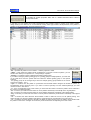
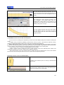
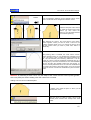
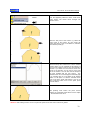
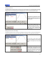
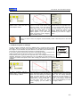
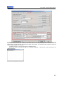
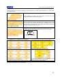
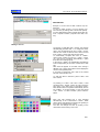
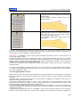
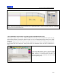
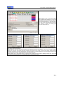
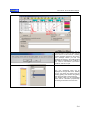
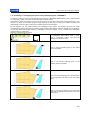
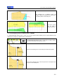
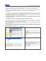
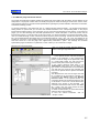
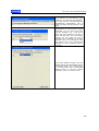
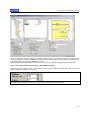
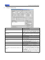
Download USER MANUAL

Transcript
User manual - EuroCAD Pattern Designer
EuroCAD
www.EuroCAD.org
EuroCAD Pattern Designer
USER MANUAL
EuroCAD Pattern Designer
Is part of the EuroCAD CAD application pack,
The complete pack contains:
EuroCAD Pattern Designer
EuroCAD Photo Digitizer
EuroCAD Spread&Cut Planner
EuroCAD Automarker
EuroCAD PlotMaster
© 2009 Advanced CAD Technologies ltd. ITN 0061 rev 01.2009
1
User manual - EuroCAD Pattern Designer
2
User manual - EuroCAD Pattern Designer
Contents:
1.
EuroCAD Pattern Designer
1.1
EuroCAD
Pattern
11
Designer:
What
it
IS
and
what
it
DOES
11
list
11
.........................................................
1.2
EuroCAD
Pattern
Designer
design
functions
…………........................................................
1.3
Definitions and explanations ……………….........................................................................
18
1.4
The workspace – what you need to know before starting a project................................
19
1.5
« Pattern » mode..................................................................................................................
24
1.5.1
Select patterns; switching between rotation and stretch mode ……….....................
24
1.5.2
Move patterns, move s using CTRL, piece origin placement..................................
24
1.5.3
Pattern paste point over point ............…………………………………………………
25
1.5.4
Pattern rotation; setting a rotation center; magnetization of the rotation center.....
26
1.5.5
Resize patterns ……………......................................................................................
28
1.5.6
Move, resize, rotate, scale patterns by exact numerical data..................................
28
1.5.7
Show/hide symmetrical pattern.................................................................................
30
1.5.8
Symmetrize in a new pattern …. ...............................................................................
30
1.5.9
Show/hide unfolded pattern......................................................................................
30
1.5.10
Unfold in a new pattern …….. ...................................................................................
31
1.5.11
Extract the external cut line on a new pattern..........................................................
31
1.5.12
Extract the internal seam line on a new pattern........................................................
32
1.5.13
Create the internal seam line as auxiliary draw inside the pattern...........................
32
1.5.14
Cut off a pattern with another (Trim) ……………………………………………..…..…
33
1.5.15
Create a new pattern from patterns intersection.......................................................
33
1.5.16
Join patterns in a new pattern...................................................................................
34
1.5.17
Create points at patterns intersection.......................................................................
34
1.5.18
Horizontal and vertical flip.......................................................................................
35
1.5.19
Pattern alignment …..................................................................................................
35
1.5.20
Block the selected pattern........................................................................................
35
1.5.21
Group/ungroup the selected patterns.......................................................................
36
1.5.22
Attach or detach auxiliary patterns to the main patterns .................………..………..
36
1.5.23
Align a pattern to the grain axis ……….....................................................................
37
1.5.24
Pattern interpolation ……..........................................................................................
38
1.5.25
Pattern color change …………..................................................................................
39
1.5.26
Change a pattern name …………..............................................................................
40
3
User manual - EuroCAD Pattern Designer
1.6
1.5.27
Edit pattern properties ……………............................................................................
40
1.5.28
Multiple pattern properties visualization and modification in the same table …........
42
« SHAPE TOOL » mode....................................................................................................
47
1.6.1
Introduction..............................................................................................................
47
1.6.2
What is a Bezier curve? ...........................................................................................
47
1.6.3
Select a point; select multiple points; select a segment..........................................
48
1.6.4
Moving a point ………................................................................................................
49
1.6.5
Moving a point by mouse drag; use ALT, CTRL or SHIFT.......................................
49
1.6.6
Move a point by the keyboard arrows ……………..……...........................................
50
1.6.7
Move points by exact coordinates setting...............................................................
50
1.6.8
Point properties........................................................................................................
51
1.6.9
Set pattern origin in a point.......................................................................................
52
1.6.10
Convert a line into curve/ a curve into line...............................................................
52
1.6.11
Set the point type: ....................................................................................................
53
- cusp, smooth, 90° defined cusp, defined cusp angles
- defining restrictions related to neighbor segments
1.7
1.6.12
Add new point; delete a point...................................................................................
53
1.6.13
Change the Bezier curve shape...............................................................................
54
1.6.14
Point alignment: vertical, horizontal, rectilinear.......................................................
55
1.6.15
Divide a segment in a given number of parts...........................................................
56
1.6.16
Smoothing a part of the pattern contour by Bezier curves........................................
56
1.6.17
Bezier interpolation for a part of a pattern contour...................................................
57
1.6.18
Change a point status: curve point or grade point...................................................
57
1.6.19
Open / Close a pattern perimeter.............................................................................
58
1.6 20
Change Bezier curve length....................................................................................
58
1.6.21
Round a corner........................................................................................................
58
1.6.22
Create a new point at a given distance from a selected point..................................
59
1.6.23
Rotate a group of points around a point..................................................................
61
1.6.24
Rotate pattern until the line between two selected points becomes horizontal ........
61
1.6.25
Bulge …………………………………………………………………………………….…
62
1.6.26
Closing a bulge …………………………………………………………….………………
65
1.6.27
Fullness ………………………………………………………………….…………………
66
1.6.28
Add a French curve to the selected pattern …………………………….……………….
67
« DRAW TOOL » mode.........................................................................................................
73
1.7.1
Introduction.................................................................................................................
73
1.7.2
Free drawing................................................................................................................
73
4
User manual - EuroCAD Pattern Designer
1.7.3
Continue to draw a piece............................................................................................
74
1.7.4
Use CTRL, SHIFT and ALT keys for free drawing......................................................
75
1.7.5
Draw a line using quotes and precise dimensions......................................................
76
A
Draw with coercion to the next line ………………………………………………….........
76
B
Draw with coercion to the next point ………………………………………………..........
77
1.7.6
Draw curves - Draw free or assisted with points and curves ....………………..........
77
1.7.7
Use CTRL, SHIFT and ALT keys for drawing free the curves....................................
78
1.7.8
Draw a curve using quotes and precise dimensions..................................................
79
A
Draw a curve by constraining to the next line ...…………………………………...........
79
B
Draw a curve by constraining to the next point ...………………………………….........
80
1.7.9
Add a French curve to a pattern ………………………………………………………......
80
1.7.10
Draw arc by three points.....………………………………………..................................
82
1.7.11
Use CTRL, SHIFT, ALT keys to draw freely an arc by 3 points..................................
82
1.7.12
Draw arc by three points using precise quotas and dimensions ……………...............
84
A
Draw arc through three points by constraining to the next line …………………..........
84
B
Draw arc by three points by constrain to the next point …………………………..........
85
1.7.13
Draw arc by two points and radius ………………………………………………….........
86
1.7.14
Use CTRL, ALT keys to draw freely an arc by 2 points and radius ......………...........
86
1.7.15
Draw arc by 2 points and radius using precise quotas and dimensions ....….............
87
1.7.16
Draw arc by two points and radius by constraining to the next line …………..............
87
1.7.17
Draw arc by two points and radius by constraining to the next point ...………............
89
1.7.18
Draw arc by two points and radius by constraining to the radius ……………..............
89
1.7.19
Draw arc by two points and angle …………………………………………………….......
90
1.7.20
Use CTRL, SHIFT, ALT keys to draw freely an arc by 2 points and angle ....….........
91
1.7.21
Draw arc by two points and angle using precise quotas and dimensions ...…............
91
A
Draw arc through three points by constraining to the next line...................................
92
B
Draw arc by two points and angle by constrain to the next point ……………..............
93
C
Draw arc by two points and arc by constraining the starting angle …………..............
93
1.7.22
Draw spiral …………………………………………………………………………………..
94
1.7.23
Draw a circle knowing the radius ………………………………………………………....
98
1.7.24
Draw a circle by constraining the next point …………………………………………......
98
1.7.25
Draw a circle by constraining the radius length ……………………………………........
99
1.7.26
Trace mode – drawing around the contour of the existing pieces ……………….........
100
1.7.27
Draw a circle or ellipse ……………………………………………………………………..
101
1.7.28
Draw a square or rectangle ………………………………………………………………..
102
1.7.29
Digi Pen digitizing …………………………………………………………………………..
103
5
User manual - EuroCAD Pattern Designer
1.8
1.9
1.7.30
Set the type of the advanced magnetize……………………………………………………………….
105
1.7.31
“Graded points” magnetizing…………………………………………………………………………….
105
1.7.32
“Intersection points” magnetizing…………………………………………………………….
107
1.7.33
“Internal points” magnetizing………………………………………………………………...
109
1.7.34
“Contours” magnetizing……………………………………………………………………….
112
1.7.35
“Parallels” magnetizing……………………………………………………………………….
112
« DIGITIZE » mode................................................................................................................
114
1.8.1
Digitizer.......................................................................................................................
114
1.8.2
Digitizing a pattern outline..........................................................................................
116
1.8.3
How to use pointer buttons to digitize a pattern.......................................................
119
1.8.4
Digitize a pattern grading..........................................................................................
120
1.8.5
Digitize the technical elements of a pattern..............................................................
120
1.8.6
Insert the pattern name and end the digitization…...................................................
127
1.8.7
Edit the digitizer settings / profile.............................................................................
128
« GARMENT TOOL » mode………………..........................................................................
130
1.9.1
Introduction...............................................................................................................
130
1.9.2
Create a notch.........................................................................................................
131
1.
Change a mark point...............................................................................................
132
2.
Convert a notch to a point…………….......................................................................
133
3.
Delete a notch………….........………….........………….........…………......................
133
1.9.3
Percent notch………………………...........................................................................
134
1.
Change the mark point.............................................................................................
135
2.
Convert a notch to a point .......................................................................................
136
3.
Delete a notch..........................................................................................................
136
1.9.4
Intersection notch.....................................................................................................
137
1.
Change the mark point.............................................................................................
138
2.
Delete a notch..........................................................................................................
139
1.9.5
Corner notch ............................................................................................................
139
1.
Delete a corner notch……………………………………………………………………..
140
1.9.6
Dependent line........................................................................................................
141
1.9.7
Translated contour....................................................................................................
143
1.9.8
Parallel to the contour...............................................................................................
145
1.9.9
Define a dart.............................................................................................................
147
1.9.10
Check the pattern: temporary dart closure, checking and adjusting of edges
149
overlapping length, reopening a dart........................................................................
1.9.11
Automatically create a dart using 4 points................................................................
152
6
User manual - EuroCAD Pattern Designer
1.9.12
Automatically create a dart using 2 points...............................................................
154
1.9.13
Operations on the dart: dart rotation; multiple darts.................................................
155
1.9.14
Operations on the dart: modify a dart cut line..........................................................
157
1.9.15
Operations on the dart: cut a pattern over dart.........................................................
158
1.9.16
Operations on the dart: convert the dart to folded dart; convert the folded dart to open
158
dart…………………….……………………………………………………………..
1.10
1.9.17
Automatic notches for the dart.................................................................................
159
1.9.18
Create a fold.............................................................................................................
159
1.9.19
Straighten a piece..................................................................................................
171
1.9.20
The seam allowance. Set the width of the seam allowance.....................................
171
1.9.21
Finishing types for the seam allowance corners.......................................................
175
1.9.22
Internal technical points.............................................................................................
177
1.9.23
Create a sequence of internal points........................................................................
179
1.9.24
Declare a pattern origin in an interior technical point................................................
181
1.9.25
Matching point..........................................................................................................
181
1.9.26
The grain axis...........................................................................................................
187
1.9.27
The text axis.............................................................................................................
188
1.
Cut a pattern on an internal line................................................................................
190
2.
Create points at the intersection between the pattern contour and the internal line.
190
3.
Delete an internal line.............................................................................................
190
1.9.28
Symmetry axis..........................................................................................................
191
1.
Edit symmetry axis………………………………………………………………………..
192
2.
Delete a symmetry axis…………………………………………………………………..
193
1.9.29
Internal elements multiselection...............................................................................................
193
« GRADING » …................................................................................................................
195
1.10.1
Introduction ….........................................................................................................
195
1.10.2
Size set…................................................................................................................
195
1.10.3
How
201
to
grade
a
point
in
EuroCAD
Pattern
Designer........................................................
a.
Point linked to the parametrical layer......................................................................
201
b.
XY grading..............................................................................................................
201
c.
Derived grading......................................................................................................
201
1.10.4
Display graded sizes for a pattern...........................................................................
202
1.10.5
The grading table of a point....................................................................................
203
1.10.6
Operations on the grading table.............................................................................
206
a.
How to modify a value in a box..............................................................................
206
7
User manual - EuroCAD Pattern Designer
b.
How to select multiple boxes in order to modify the values simultaneously.........
206
c.
How to modify all values in a column simultaneously ............................................
206
d.
How to increase / decrease values by addition / subtraction..................................
207
e.
How to save a grading rule in a file. How to load and apply a grading rule from a
207
file...........................................................................................................................
1.11
1.10.7
Operations for fast grading modifications................................................................
210
a.
Grading linearization...............................................................................................
210
b.
How to symmetries on X, Y and XY axis................................................................
211
c.
How to rotate a grading...........................................................................................
212
d.
How to copy grading from one point to another......................................................
213
e.
Separate copy on X and Y axis between the points on a pattern...........................
217
1.10.8
Modify the grading with the keyboard arrows..........................................................
218
1.10.9
Modification of one size without modifying the other set sizes……………………..
219
1.10.10
Alignment of the graded sizes. Pack in point and pack on the line…………………
222
1.10.11
Point grading on a direction……………………………………………………………..
224
1.10.12
Change the base size………………........................................................................
225
1.10.13
Distribution of model sizes on grading groups with different base sizes…………..
226
1.10.14
Change the grading group for a pattern ………………………………......................
228
1.10.15
Add a new size into an existing size set ……………………………...………….......
229
1.10.16
Delete a size set from an existing size set…………………….................................
234
1.10.17
Cancel a point grading. Cancel the grading on a model……………………………..
235
1.10.18
Grading the internal technical points. Grading the axes.........................................
236
1.10.19
Grading a notch…………………………………………………………………………..
237
1.10.20
Align the graded sizes to the grain axis………………………………………………..
238
1.10.21
Automatic calculation of a point grading relative to the grading of the nearby points
238
1.10.22
Derived grading ………………………………………………………………………….
239
1.10.23
Copy a graded pattern from one model to another ………………………….…….
240
« MEASUREMENT AND CHECK TOOL» mode.............................................................
243
1.11.1
Distance measurement between two points on the pattern perimeter …………….
243
1.11.2
Distance measurement between two points on a straight line ……………………
244
1.11.3
Compose measurements ……………………………………………………………..
246
1.11.4
Show/hide distances on the patterns ………………………………………………….
248
1.11.5
Angle measurement …………………………………………………………………..
248
1.11.6
Surface measurements ……………………………………………………………….
249
1.11.7
Measurement table (Watcher) …………………………………………………………
249
1.11.8
Add measurements compose in the watcher ………………………………………
252
8
User manual - EuroCAD Pattern Designer
1.12
1.11.9
Display increase differences from a size to another and quotes from table ………
253
1.11.10
Select the measurements to be printed in the product technical sheet ……………
254
1.11.11
Save and load names measurement from the watcher ……………………………
254
1.11.12
Pasting or overlapping two patterns on the indicated points – ASSEMBLY ……..
256
1.11.13
Overlapping points in different patterns – MARRY ………………………………….
257
1.11.14
Simulate the combination by sewing, for two patterns – WALKING PATTERNS
260
1.11.15
Notch translation from one contour segment to another ………………………….
261
«Parametrical design mode – Made to Measure» ………………………………………..…
263
1.12.1
Introduction to parametrical design ……………………….…………………………
263
1.12.2
Developing a new project by parametrical design …………………………………
265
1.12.3
Explaining the workspace in the parametrical mode ………………………………
266
A.
The workspace ………………………….………………………….……………………
267
B.
Script area ……………………….………………………….………………………….
268
C.
Geometrical operation description and editing area ……………………………….
268
D.
The quote list area ……………………….……………………………………………
268
E.
Buttons for the geometrical design functions ……………………………………….
269
1.12.4
The design script ……………………….……………………………………………...
269
1.12.4.1
What is the design script ……………………….………………………
270
1.12.4.2
How to add a new step ………………………….……………………..…
270
1.12.4.3
How to delete a step in the script list ………………………………….
270
1.12.4.4
Show/hide the rule for a step in the script …………………………….
270
1.12.4.5
How to copy the script steps …………………………………………...
270
1.12.4.6
Save or load a script ……………………….……………………………
270
1.12.4.7
What means the step colors? ………………………….………………..
270
1.12.5
Design functions....................................................................................................
271
1.12.5.1
The list of the used design functions.....................................................................
271
1.12.5.2
How to complete a function ……………………………............................................
271
1.12.5.3
Defining the design functions …………………….…………………………………....
272
1.
Free point...............................................................................................................
272
2.
Point at XY from another point...............................................................................
272
3.
Horizontal triangulation point …………………….………………………………….. ..
272
4.
Vertical triangulation point …………………….………………………………………..
273
5.
Point on a line at a given distance from another point …………………….………
273
6.
Point on a vector reported to horizontal axis …………………….…………………
273
7.
Point on a vector reported to another line …………………………………………..
274
9
User manual - EuroCAD Pattern Designer
8.
Point in the middle of a segment …………………….………………………………
274
9.
Proportional point on a segment …………………….……………………………….
275
10.
Division points on a segment …………………….…………………………………..
275
11.
Point on the perpendicular …………………….……………………………………...
276
12.
Point on the median line …………………….………………………………………..
276
13.
Perpendicular projection …………………….………………………………………...
276
14.
Point by triangulation …………………….…………………………………………….
277
15.
Dart edge point …………………….………………………….………………………
277
16.
Point on a parallel line …………………….………………………….……………….
278
17.
Point at intersection …………………….……………………………………………...
278
18.
Point on the perpendicular line on a line with given angle ………………………...
279
19.
Edge point of the dart-angle …………………….……………………………………
279
20.
Two circles tangent points …………………….………………………………………
280
21.
Contact points of a tangent to a circle …………………….…………………………
280
22.
Point at a given distance on a circle.....…………………………………………….
281
23.
Parallel to line …………………….…………………………………………………….
281
24.
Point on tangent to circle …………………….………………………………………..
281
25.
Point the center of a circle …………………….………………………………………
282
26.
Segment between two points …………………….…………………………………..
282
27.
Line between two points …………………….………………………………………..
283
28.
Circle defined by center and radius …………………….……………………………
283
29.
Circle defined by center and contour point …………………….……………………
283
30.
Circle defined by diameter …………………….………………………………………
284
31.
Circle defined by three points …………………….…………………………………..
284
32.
Circle defined by center point and circumference ………………………………….
284
33.
Circle defined by contour and radius …………………….…………………………..
285
34.
Circle defined by center point and tangent to a specific line ………………………
285
35.
Circle defined by center point and tangent to another circle ………………………
286
36.
Circle with contour point and radius, tangent to a line ……………………………..
286
37.
Circle with contour point and radius, tangent to a line ……………………………..
287
1.12.6
Draw a pattern and anchor to the parametrical layer ………………………………
287
1.12.6.1
Free draw and anchoring the pattern point by point ……………………………….
288
1.12.6.2
Direct anchoring during a pattern design …………………….……………………..
288
10
User manual - EuroCAD Pattern Designer
1.12.7
How to adapt a direct designed product for automatic grading …………………..
289
1.12.7.1
How to adapt a direct designed pant for automatic grading ………………………
290
1.12.7.2
How to adapt a direct designed skirt for automatic grading ……………………….
293
1.12.8
Getting a size set for a model that was created by parametrical design ………...
295
1.12.9
„Made to measure” size – How to create an atypical size or the work on demand
296
1.12.10
How to create a classic skirt pattern in the Parametrical mode ...………………..
299
«General
302
1.13
functions
in
EuroCAD
Pattern
Designer»
…………………………………..
1.13.1
Edit dependency groups for the patterns in a model ……………………………...
302
1.13.2
Edit the project technical sheets …………………….……………………………….
305
1.13.3
Print project and pattern technical sheets.....………………………………………
308
1.13.4
Printing patterns on a plotter. RS274D file export …………………………………
310
1.13.5
DXF, Gerber, Assyst, Lectra or Investronica file type import …………………….
314
a.
Import DXF and XF-AMAA files …………………….………………………………..
314
b.
Import Gerber native files (*.tmp) ………………….……………………………...
318
c.
Import native Assyst files (*.zip) ..............………….……………………………….
321
d.
Import native Lectra file (*.iba and *.vet) ………………….………………………..
323
e.
Import native Investronica (*.EXP) files …………………….……………………….
324
f.
Import native Investronica files from database ……………………………………
326
1.13.6
Export a project in another standard DXF format …………………………………..
329
1.13.7
General program settings …………………….……………………………………….
333
a.
General Settings …………………….………………………….……………………...
334
b.
Design settings …………………….………………………….……………………….
335
c.
Technical elements settings …………………….…………………………………….
337
d.
Colors settings …………………….………………………….………………………..
348
e.
Settings for plotter printing …………………….……………………………………..
339
f.
Keyboard settings …………………….………………………….…………………….
340
1.13.8
Check the patterns prepared for cut …………………….…………………………..
341
1.13.9
Check selected patterns …………………….………………………………………..
342
Remote Assistance …………………………………………………………………....
343
EuroCAD workstation - Hardware Specifications................................................
347
Appendix
01
Using Calcomp cursor wireless EuroCAD Alpha digitizer …………………………...
349
11
User manual - EuroCAD Pattern Designer
Appendix
EuroCAD Beta wired pointer usage …………………….………………………………
02
Appendix
03
Application …………………….………………………………………………………..
351
353
EuroCAD Pattern Designer
1.1 EuroCAD Pattern Designer: what it IS and what it DOES
EuroCAD Pattern Designer – EuroCAD Pattern Designer is the main program in the EuroCAD CAD package. This
is the program destined to pattern design, product grading and checking, pattern matching for further sewing
operations. EuroCAD Pattern Designer helps you digitize patterns or can import models sent by the clients.
EuroCAD Pattern Designer insures the patterns for the next steps of the technological flow.
1.2 EuroCAD Pattern Designer Design functions list
EuroCAD Pattern Designer has 8 working modes, each with different functions:
Button
symbol:
Mode:
PATTERN TOOL
SHAPE TOOL
DRAW TOOL
DIGITIZE
Available functions:
Resize, align, overlap, join, cut, intersection, symmetrization, fold-unfold,
extract seam allowance, interpolation, align to grain axis, pattern cutting
parameters settings (fabric, symmetry, double pattern).
Convert lines and curves, define angles in corners, point alignment, rotate
and change point position, interpolation
Technical drawing from base geometrical shapes, from free lines or from
lines with predefined length and angles; drawing with points with given
coordinates
Pattern contour digitization, grain axis, notches, symmetry line, internal
points, pattern name and information
GRADING
Edit size set, grading on reference point with grading table or special keys,
align sizes in different pattern points, symmetrization, rotation, grading
copy, change base size
GARMENT
TOOL
Work with: darts (rotate, close, cut), folds (fold, unfold), notches, grain axis,
seam allowance, symmetry axis, translate contour, parallel to the contour,
internal technical points
MEASURE AND
CHECK TOOL
Direct length measurements, contour length on the sewing line, angles and
surfaces measurements, automatic notch transfer between patterns to be
sewed together, matching patterns for verifications, watcher
PARAMETRICAL
Develop the parametrical layer, load script, save script, insert step into the
script, delete step from the script, fast quote change for the MTM measure
Standard toolbar
Create a new project
Open a saved project
12
User manual - EuroCAD Pattern Designer
Save project to a file
Cut the selected pattern and copy it into the clipboard for further usage
Copy the selected pattern into the clipboard
Extract the pattern from clipboard and paste it into the current project
Print the project technical sheet
Print patterns on a plotter
Cancel last operation
Remake last canceled operation
Show / hide pattern name
Show / hide pattern control grid
Show / hide grading
Show / hide seam allowance
Show / hide measurements table
Show/hide distance on the patterns
Change the selection mode: internal or contour
Mix view between pattern layer and parametrical layer
Display the zoom level and allows zoom in and zoom out operations
Zoom to the selected area
Zoom at the previous zoom level
Zoom to selected patterns
Zoom to whole project
Arrange the patterns in a project on the cut line
Edit pattern group dependency
Edit the project technical sheets
13
User manual - EuroCAD Pattern Designer
Pattern checker
Preview patterns as they will be printed on plotter
Open help files
PATTERN mode toolbar
Temporary pattern symmetrization
Permanent pattern symmetrization by creating a new pattern
Create a new pattern on the external cut line and adds the seam allowance
Create a new pattern on the internal seam line, eliminating the seam allowance
Temporary pattern unfold
Permanent pattern unfold by creating a new pattern
Block the selected pattern to avoid accidental changes
Horizontal flip
Vertical flip
Group selected patterns
Ungroup selected patterns
Attach one or more auxiliary patterns to the main pattern
Detach one or more auxiliary patterns to the main pattern
Create a new pattern from selected patterns intersection
Cut a pattern with another
Create a new pattern by joining the selected patterns
Create new points on selected patterns contour intersection
Align selected patterns
Rotate selected patterns to align the grain axis horizontally
Interpolate all pattern segments
Choose pattern color
14
User manual - EuroCAD Pattern Designer
Extract the internal seam line with gradings
Extract the external cut line with gradings
Create seam line inside the pattern
SHAPE TOOL mode toolbar
Join selected points and close pattern perimeter
Open pattern contour in the selected point
Set the selected point as « CUSP »
Set the selected point as « SMOOTH »
Set the selected point as « 90°DEFINED CUSP »
Set the selected point as « DEFINED CUSP ANGLE»
Transform selected curve into line
Transform selected line into curve
Convert polygon segment into Bezier curves, to smooth contour
Bezier interpolation for the selected segment
Add a point on the contour
Delete selected point
Align selected points horizontally
Align selected points vertically
Align selected points rectilinear
Divide segments in a given number of parts
Round selected corner
Rotate selected group of points around the last selected point
Create a new point at a given distance from a selected point.
15
User manual - EuroCAD Pattern Designer
Rotate pattern until the line determined by the selected two points becomes horizontal
Bulge pattern by cleaving and rotation between two points
Bulge close
Fullness
Add a French curve to the selected pattern
« DRAW TOOL » mode toolbar
Draw free or assisted, with points and lines
Draw rectangles
Draw ellipses
Draw free or assisted (with points and curves)
Add french curves to pattern contour
Draw arc by 3 points
Draw arc by 2 points and radius
Draw arc by 2 points and angle
Draw spiral
Draw circle
Trace mode – drawing around the contour of the existing patterns
Digi Pen digitize
« GARMENT TOOL » mode toolbar
Create a percent notch
Create a distance notch
Create intersection notch
Create corner notch
Create a dependent line
Create an interior line by translating a part of the contour.
16
User manual - EuroCAD Pattern Designer
Create an interior line by a parallel to a contour segment.
Create symmetry axis
Create grain axis
Create text axis
Create technical interior point
Create fold
Create a sequence of separate folds
Create a sequence of mix folds
Declare dart
Create dart using 4 points
Create dart using 2 points
Edit seam allowance and corner finishing type
Create a sequence of internal points
« GRADING » mode toolbar
Edit-open size set
Edit the grading table of a point
Edit point grading on direction
Linearize grading steps in the selected point
Align temporary grading sizes to the selected points
Align permanently grading sizes to the selected points
Align graded sizes to the grain axis
Copy grading horizontally and vertically
Symmetrize the selected points grading
Rotate grading rule 90 degrees
17
User manual - EuroCAD Pattern Designer
Load and apply the grading rule
Save a grading rule into a file
Automatically calculate the point grading from the neighbor points grading
Cancel the grading of the selected points
Modify the shape of the pattern on the base size without changing the other sizes
Cancel the “manual modification” of one sizes for the selected points
Copy point grading in clipboard (Ctrl +F)
Transfer grading from clipboard (Ctrl + G)
Activate Drop Grading
Activate Grade Grading
Activate Extra Grading
Activate Spec Grading
« Measure and Check Tool » mode toolbar
Assembly two patterns on the selected points
Assembly (Marry) two patterns in a point
Combine two patterns on a specified direction
Translate notches from a pattern to another
Measure the distance between two points on a pattern seam line
Measure direct distance between two points on a contour
Measure angles from three points
Measure a pattern surface
18
User manual - EuroCAD Pattern Designer
1.3 Definitions and explanations
To understand and master the EuroCAD Pattern Designer functions we must clearly define end explain the technical
terms.
Project
A project represents a complete set of patterns that will be cut from one or more fabric types and then sewed together
to create a product.
In EuroCAD Pattern Designer program, a project represents a file that contain all information about pattern shape on
all sizes, together with other important information (product technical sheet, measurement table, fabric types, size set
etc).
These files are saved on the computer in a file with *.PAT extension.
Pattern
1.
2.
3.
4.
5.
6.
7.
A pattern is a part of a model it is represented by a contour with a specific shape and technical elements as: notches,
grain axis, symmetry axis, seam allowance, pattern name and other information regarding the pattern etc. The pattern
contour is formed by points with specific coordinates; the points are connected by lines and curves.
Pattern attributes: simple, half symmetrical, pattern designed on internal seam line, pattern designed on the
external cut line. A pattern can be multiplied in a project by indicating the number of copies for the simple
pattern, the number of symmetrical doubles on horizontal, vertical or horizontal and vertical.
According to their function in the final product, patterns can be classified as follows:
Simple pattern – a pattern that appears only once on the final product, as displayed
Symmetric (half) – a pattern that will be doubled by symmetrization around an axis, just before cutting;
this type of pattern has a defined symmetry axis that is a contour segment around which the pattern symmetrical will
be built; if you set a symmetry line to a pattern, it will be automatically set as « symmetrical - half »; if you remove the
symmetry axis, the pattern becomes « simple »
Multiple « D » – is a pattern that appears many times, identically, in the final project, without mirroring
the resulting patterns
Symmetrical flipped « Fx » « Fy » « Fxy » - are patterns that appear many times in the final project
but that are mirrored from the original pattern.
Pattern designed on internal seam line – is a pattern with the contour representing the pattern seam
line; EuroCAD Pattern Designer will automatically add the seam allowance to this type of pattern before cutting and
according to designer specifications.
Pattern designed on the external cut line - is a pattern with the contour representing the pattern
cutting line; no seam allowance addition is needed; generally, the digitized patterns are checked as « designed on the
external cut line »
Auxiliary pattern - is a pattern used only in the design step. These patterns are not imported in
EuroCAD Spread&Cut Planner or EuroCAD Automarker programs.
Pattern type can be set in « PATTERN TOOL» mode.
Points
A pattern contour is formed by multiple points connected by lines and/or curves. The points can be corners
or can be located on curves and lines. Each point has 2 coordinates, on horizontal and on vertical from the pattern
origin point. Pattern origin can be any point on the contour and can be reallocated without any contour shape
changes.
To modify a pattern shape you can change the point type and position, you can add or delete points or you
can change the curve shapes. These operations are available in « SHAPE TOOL » mode. There are two types of
points: graded points and curve points.
The points can be defined from the pattern origin, from a parametrical point or as curve points.
Bezier curve; Control points; End points
The contour points are connected by lines and curves. EuroCAD Pattern Designer uses a special curve type
named « Bezier curve » from the French mathematician that invented them. A Bezier curve is a curve between two
points whose shape can be adjusted by moving two control points.
Bezier curves may reproduce accurately the natural and anatomical shapes, being very useful for pattern
contours tracing. All you need to know about Bezier curves is that they are defined by 4 points: 2 end points and 2
control points; moving these points are modifying the curve shape.
Size set
A size set is a collection of sizes. They can be noted as « 12, 14, 16, 18, 20, 22 » or « Small, Medium,
Large » or by any other notation. These names are registered in a table and can be associated to the effective
dimensions of some important quotes for those sizes. The dimensions registered in that table are just informative and
can be useful during grading process. To edit a size set or to create a new one, you must enter the « GRADING »
mode.
19
User manual - EuroCAD Pattern Designer
Grading
Size adjustment for each pattern in order to fit the size specifications of each size is an operation called
GRADING. To grade a project, you have to individually grade each pattern in it. To grade a pattern, you must grade
all significant points on its contour; these points are called « Grade points ».
Grading a point (point grading rule) means to establish the coordinates for the point movement between
sizes; these coordinates are mentioned in the so called grading table.
You can set grading by setting the increase step from a size to another and by setting the total modifications
from the base size.
The points with no grading are called « simple points » and are automatically graded by EuroCAD Pattern
Designer according to neighbor graded points.
Grading can be done manually or automatically, by applying the grading rules created and previously saved
on the computer.
The points can be set as « graded points » or « simple points » in « GRADING » mode.
1.4 The workspace – what you need to know before starting a project
Beside design, grading and checking knowledge you will need basic knowledge on computer work: open
and save the projects, undo operation mistakes, display the patterns in a project., page orientation.
THE STANDARD TOOLBAR.
Zoom level
In order to perform various operations you may need a general project overview or you may need a higher
detail on a smaller pattern. For this operation you can use the magnifiers in the standard toolbar, or the shortcuts.
Zoom out means drawing reducing, while zoom in means drawing enlargement.
Zoom buttons have the following facilities:
•
•
•
you can drag the interactive cursor toward « + », to zoom in or toward « – » to zoom out
zoom to selected area (click on this button and then click on the left mouse button and drag to define
the region of interest)
get back to the last zoom level
20
User manual - EuroCAD Pattern Designer
•
zoom to selected object (the image magnified for a selected object to fill the workspace)
•
zoom the whole project
Useful zoom shortcuts are :
F2 – Zoom in (enlarge the image)
F3 – Zoom out (shrink the image)
F4 – Zoom to selected pattern
F5 – Zoom to the whole model
Mouse wheel
– Zoom to the region where the mouse cursor is located. The zoom can be in or out
according to the mouse wheel direction rotation.
•
•
•
•
•
Keep «Space » key pressed to transform the cursor shape into a little hand. When the cursor has this shape, you can
move the work space by mouse drag.
Pattern duplication: Copy, cut, paste;
-
To copy a pattern in the same project or between two projects, you must use CUT or COPY and PASTE commands.
Usefully the operation order is as follows:
Click to select a pattern
Click on COPY button (the pattern is copied and temporary placed in a computer memory area called
Clipboard)
If you want to copy the pattern in the same project, click on PASTE button (pattern is extracted from the
computer memory and placed visibly in the same project)
If you want to copy the pattern in another model, after copy you must open the other project and then to click
on PASTE button
1.
2.
3.
Select the pattern
Click on COPY button
Click on PASTE button
By using COPY button, the original pattern is kept and a new pattern is created; this new pattern is identical to the
original pattern. If you copy a pattern from a model to another and you want to copy the grading too, the destination
model must contain the same size set as in the original project. (see chapter 1.10.17 - GRADING). If you copy the
pattern in the same project, the copied pattern will be displayed initially overlapped on the original pattern and must
be moved in order to avoid confusions.
If instead of COPY button you are using CUT button, the original pattern is deleted and after clicking on PASTE
button, only the copy will remain.
The PASTE command can be applied multiple times; each time you click on PASTE, you will get a new pattern copy.
A fast way to duplicate the pattern without using COPY - PASTE commands is described below:
Click to select the pattern, drag and move it with the mouse and before release the mouse button to leave the pattern
in the new position, click simultaneously on the right mouse button. You will create a pattern copy, without moving the
original pattern.
Start a new project
To start a new project you must click on « Create new project » button. When you click on this
button, a new workspace is initiated; here you can start a project design. The project name will
be set at the first save. For a new project it is important to fill data regarding the product
technical sheet.
Open a saved project
To open a previously saved project, click on « Open project » button and then select a saved
project. The project content can be previewed in a preview window. If in Project Technical
Sheet the user introduced a drawing of the model, than is possible to preview it when will open
the project ( see chapter 1.13.2). For this you must check the message « Preview product
drawing ». If the model is not displayed in the preview window then it will not be opened
(probably a wrong format).
Save a project
When you finish designing a project and periodically during working process you must save
changes by clicking on the « Save project » button.
The program creates a backup file each time you save a project on a new name. This file,
named « backup of – model_name.PAT » contains the previous project content. Backup
means a spare copy. Thus, if you have operated changes and then you have saved the project
but you want to go back to the previous project state and content, you may open the backup
file.
Start new project
Open saved
project
Save project
21
User manual - EuroCAD Pattern Designer
EuroCAD Pattern Designer can automatically save the model at a predefined interval (usually 2-3 minutes). Even if
the computer is blocked or resetting you will loose only the changes operated in the last minute (max 2 minutes) so
as the changes can be easily recovered. To avoid loosing a PAT file even if it was never saved, an auto backup file is
created.
At the first time save, you must enter the project name; on further saving the program will save changes in the same
file.
If you want to save a file in a new folder, in the Save window you must click on the button « Create e new folder » in
order to create a new folder on the hard-disk; here you can save the PAT file.
Undo – cancel last changes and go back to the initial state
If you want to cancel the last operation and to bring back the patterns on the state before
operation then you must click on « Undo » button. EuroCAD Pattern Designer has a 10
levels undo system.
Redo – remake last changes
If an operation was cancelled by using « Undo » button, you can remake it by a click on
« Redo » button. EuroCAD Pattern Designer has a 10 levels redo system.
Undo – cancel last
operation
Redo – recovers
last cancelled
operation
Reference grid
To facilitate user dimensional orientation, you can display a grid with 10 cm spaced grid
lines. Click on « Show/hide grid » button to show/hide the grid; if the button is down then the
grid is displayed; if the button is up, the grid is hidden. In the settings module you can adjust
the distance between the grid lines.
It is useful to place the pattern origin on a grid line intersection. For a fast and accurate
alignment of the pattern origin in the grid line intersection click to select the pattern and drag
it with the mouse while holding down ALT key; the object will remain fixed with the origin in a
grid intersection point..
Pattern name display
Each pattern in a project must have a name. Pattern name can be set when the pattern is
selected in « PATTERN » mode. Sometime, displaying all pattern names can be
embarrassing; thus you can use the « Show/hide pattern name » button that shows/hides
the pattern names on the screen. Pattern name is displayed together with the centered
current size.
Print the project technical sheet
In EuroCAD Pattern Designer you can realize documents that contain information about the
product –« Technical sheet » or the patterns -« Pattern sheet ». To print these documents
you must click on the « Print project technical sheet »
Print patterns on a plotter
The patterns on a project can be printed at natural scale on a plotter. First, you must obtain
a HPGL-PLT file format. Then, if you want to print pattern on a plotter you must click on the
button « Export as PLT the selected patterns ».
Arrange patterns on the cut line
When you click this button, the patterns will be arranged so as they will not intersect when
the seam allowance is displayed, or when the patterns are symmetrized or unfolded.
Thus, if you want to print the patterns in « overlapped mode », you must use this button to
arrange the patterns.
Show/hide grid
Show/hide pattern
name
Print project
technical sheet
Export as PLT the
selected patterns
Arrange patterns
on the cut line
Show / hide
seam allowance
22
User manual - EuroCAD Pattern Designer
Show / hide seam allowance
Patterns on a project are correctly designed on the internal seam line on which you must add the seam allowance to
obtain the external cut line. To show or hide the seam allowance for single or multiple pattern, you must select those
patterns and then click on the button « Show / hide seam allowance »
Show / hide grading
Current work on a pattern is done on the base size that is displayed on the screen. If you
want to display the other sizes for single or multiple patterns, you must select these patterns
and then click on the button « Show / hide grading »
Show / hide measurement table
The measurements done on a pattern can be memorized in a measurement table. To show /
hide the measurement table for a pattern you must click on the button « Show / hide
measurement table »
Show / hide distances on the patterns
Show / hide
grading
Show / hide
measurement
table
Show / hide
distances on the
patterns
The line or curve dimensions between two graded points can be displayed on all patterns
from the model without making any measurements before. To display the distances on the
patterns must press « Show / hide distances on the patterns »
Edit pattern dependency groups
For the patterns designed on plaids and stripes fabric you must edit the dependency groups
for all patterns. Thus, you must click on the button « Edit pattern dependency groups » and
you must set the groups as described in the chapter 1.12.1.
Change the selection mode: internal or contour
You can select the patterns with mouse click not only on the contour but also internally. To
change the selection mode, click on « Change the selection mode: internal or contour » or
open the « Model » menu and select « Contour selection » option. This option is very useful
when you have overlapped patterns on screen.
Edit the product technical sheet
Edit patterns
dependency
groups
Change the
selection mode:
internal or contour
Beside the pattern you will need to save other important information regarding project
description: the finished product sketch, technical details on finishing, information on product
type, client, command etc.
This information can be entered by accessing « Project » menu and the « Edit product
technical sheet » submenu.
Edit product
technical sheet
Check the selected patterns
Check the selected
pieces
23
User manual - EuroCAD Pattern Designer
Before finishing a project you must check the patterns. If you click on the button « Check the selected patterns », the
EuroCAD Pattern Designer program will automatically check the designed patterns and will display the check results
(see chapter 1.12.9 ).
Check patterns ready to cut
After you check the designed pattern you can make an automatically check for the patterns
ready to cut. You must click on the button « Check patterns ready to cut » in order to check
automatically the patterns on the cut line for all sizes in the size set. The results will be
displayed in an « Assistance » window (see chapter 1.12.8 ).
What is this?
When you click on this button in the toolbar you can open the help files associated to the
current active state of EuroCAD Pattern Designer program.
You can obtain the same result by a click on « Help » in the Menu Bar and then selecting
the « What is this? » option.
After you click on this button, near the mouse it will be displayed the question mark sign. If
you click on the button « What is this? » and then you click a element in the program, a help
window opens that will contain detailed explanations regarding the selected element.
Check patterns
ready to cut
What is this?
The Pattern bar
In EuroCAD Pattern Designer, you have the possibility to view all patterns from the
opened project, in a table called Pattern bar, placed on top of the screen. This table can be
show or hide on the screen, depending on user wishes, using the “Show/Hide” button.
You can use the stock area to select a certain pattern on the screen. For
this, first you must activate the “Select the patterns on the screen” button, and
then click on the pattern, in the stock area. This function is helpful, when you
have patterns, having similar shapes but different names, because here, you can
see the name of the pattern very clear.
When selecting one pattern, the background for the selected pattern
becomes black, and the pattern contour turns into the old background color
(white). The selected pattern becomes surrounded with green squares in the work area.
You can select many patterns in the stock area-using SHIFT key from the key board.
In addition, you have the possibility, to use the stock area selection as a
zoom to the selected pattern. For this, you must use the “Zoom to the
patterns on the screen” function together with the previous one. While these
two functions are active, when selecting one or many patterns from the stock
area, only the selected patterns will come in front of the screen.
Warning! The selected patterns will not be moved from them place. If there
are some other patterns, next to the selected one, they will come together
with in the zoom area. The selected patterns will be surrounded with green squares in the work area and having
green shape; the others will remain with its own contour color.
1.5 « Pattern » mode
24
User manual - EuroCAD Pattern Designer
To enter this mode, you must click on « Pattern » button
The cursor in this mode is
1.5.1 Select patterns; switching between rotation and stretch mode
To select a pattern you must click on it with the left mouse button. On the pattern sides and corners will appear small
squares; you can pull from these squares to modify pattern shape (for this, you have to press CTRL or SHIFT).
If you click again on a selected pattern you will go in « rotation » mode and the corner control points will transform
into rotation symbols; if you drag these symbols you can rotate the pattern.
Unselected pattern
Selected pattern
Pattern selected in rotation mode
When you select a pattern, its name and type (in brackets) will be
displayed in the status bar (in the lower part of the application).
If you have selected a symmetrical pattern, near its name appears an « S » between brackets; if you have selected a
double pattern, near its name appears a « D » between brackets; if you have selected a mirror double pattern, near
its name appears an « MD » between brackets.
By defining a selection region with mouse click and drag, you can select one or mode
patterns.
Hold down
to select/deselect
patterns one by one
while clicking on them
If you click on another pattern or near a pattern, the selection is lost. To select consecutively multiple patterns you
must click on them consecutively while holding down SHIFT key. Similarly, if you want to deselect one or more
pattern from a selected group, you can click consecutively on those patterns while holding down SHIFT key.
When you select multiple patterns by using SHIFT key or by defining a selection
region, in the status bar it will be displayed the number or selected main and
auxiliary patterns.
1.5.2 Move patterns, move patterns using CTRL, pattern origin
placement.
Patterns can be easily moved with the mouse, with the keyboard arrows or by
introducing the movement distances in the specific boxes. Click to select a pattern and
drag it with the mouse. To move a pattern only on horizontal or vertical, you must hold
down CTRL key.
The selected patterns can also be moved by the keyboard arrows. On each keyboard
arrow press, the patterns will move with 10 mm; if you hold down CTRL while pressing
keyboard arrows, the movement step will be smaller - 1 mm. The step length can be
changed in the Settings module.
To place the pattern origin in one of the grid points, while dragging the object with the
mouse, hold down ALT key.
This tip is very useful to paste two patterns in a single point. To do this, the points to be
overlapped will be declared as origins for the two patterns.
Hold down
to restrict pattern
movement horizontally
or vertically
Use arrows
to
move patterns more
accurately
25
User manual - EuroCAD Pattern Designer
Hold down
to place patterns
with the origin in a
grid point
The two pieces to be pasted.
Hold down ALT and drag each
piece until the origins are fixed in
1.5.3 Pattern paste point over point
In « Pattern » mode you can paste patterns point over point.
A faster and more efficient paste method « point over point » for two patterns is represented by the
placement by magnetization using ALT key. Grab the pattern from a point, hold down ALT key and drag
up to the point where the patterns will be pasted. By magnetization, the patterns will be perfectly
positioned point over point.
In « Pattern » mode, click to select the point to be overlapped.
This point will appear with a small red circle around it.
Hold down ALT key. When you press the ALT key, all graded
points on the other patterns will be marked. The selected point
can be magnetized over any of the marked points.
Hold down
to paste the selected point
by magnetization over
other points
Drag the selected point by moving the mouse up to the point
where you want to paste the pattern. While patterns are
getting closer, they are perfectly overlapped point over point
by magnetization.
1.5.4 Pattern rotation; setting a rotation center; magnetization of the rotation center.
26
User manual - EuroCAD Pattern Designer
A pattern or a selected group of patterns can be rotated with the mouse. Select the
pattern and click on it once again; the rotation symbols appear in the pattern corners
and the rotation center symbol appear on the pattern. The rotation center can be moved
with the mouse in any position so as the pattern will rotate around that position. If you
drag the rotation symbols in the pattern corners you will rotate the pattern or the group
of selected patterns around the rotation center.
Hold down
While rotating a
pattern to rotate it
with exact angles
45°, 90°, 180°.
First, the rotation center will be
centered to the pattern.
The rotation center can be moved to
another position; the pattern will rotate
around the new position
To rotate a pattern by exact 15°, hold down CTRL while moving the mouse. You will be
able to fast rotate the pattern by 45, 90, 180 degrees.
If you hold down ALT key while moving the rotation center, you can magnetize it on any
point, so the point will become the rotation center.
Using the rotation center magnetization by holding down ALT key is useful when you want
to check the pattern joining in a specific point.
Hold down
To paste the rotation
center over other
points by
magnetization
In « Pattern » mode, click to select the pattern; click again for the rotation
symbols to appear in the corners.
Grab the pattern in the point to be pasted, hold down ALT key and
drag near the point of the destination pattern where you will paste
the source pattern.
27
User manual - EuroCAD Pattern Designer
By magnetization, the patterns will perfectly overlapping point over
point.
Click to select the pattern rotation center and hold down ALT key;
then drag up to the point where you want the magnetization to
occur.
Rotation center magnetization in the point where the two patterns
are overlapped, allows pattern rotation so as the joining can be
checked.
28
User manual - EuroCAD Pattern Designer
1.5.5 Resize patterns
It is rarely used. Patterns can be stretched or shrink or proportionally resized. To resize a pattern, click to select it,
hold down SHIFT key and drag the corner and lateral resizing points with the mouse.
If you drag the corner points, the resizing process is proportional; if you drag the lateral points, the pattern will be
resized only on that point movement direction.
If you hold down CTRL key while dragging the lateral resizing points, the changes will be more accurate by a specific
multiplication of the base size (double, triple, double symmetrically, triple symmetrically). To multiply the base size,
while holding down the CTRL key you must drag the resizing points with a distance that equals the double or triple
bas size; otherwise no change appears.
Vertical resize
Proportional resize, using the corner
resize point
Horizontal resize
Hold down
Hold down
for a free pattern
resize
for an accurate
pattern resizing
You can easily FLIP a pattern by horizontal resizing
while holding down CTRL key
1.5.6 Move, resize, rotate, scale patterns using exact numerical data
To set the exact patterns sizes and positions, to rotate them under a precise
angle or to resize them accurately, you can use editing regions in the right
side menu of EuroCAD Pattern Designer. In this area, is a panel dedicated
to 4 types of operations: resize, move, rotate, scale.
IMPORTANT: these panels are visible only in « Pattern » mode. In other
working modes there are displayed different panels, specific to other
operations. To enter « Pattern » mode see the beginning of chapter 1.5.
You can do only one modification to a pattern or to a selected group; for
example you can do just resize, just scale, just movement or just rotation at
once. You must press the “Apply” button after each modification.
29
User manual - EuroCAD Pattern Designer
Resize
When you select a pattern, in the corresponding boxes
appear the pattern actual dimensions. You can modify
the values in the boxes, and then click on « Apply »
button to resize the pattern to the new dimensions.
If you check the box « Resize proportional » then the
program will automatically adjust a dimension
proportionally to the other; thus the ratio between
pattern height and width is conserved.
Scale
This area is dedicated to scaling. Here you can scale
the patterns horizontally or vertically or you can mirror
patterns horizontally or vertically.
To apply changes after scale setting, you must click
on « Apply » button.
Move
In the move settings there are two boxes: one for
horizontal (DX) and one for vertical (DY) movement. In
these boxes you can enter the distance (positive or
negative) for the pattern to be moved in the two
mentioned directions.
To apply the changes you must click on « Apply »
button.
Rotation
In the rotation area, in a specific box, you must enter
the pattern angle value in degrees.
Under the angle value box are two more boxes in
which you can set the pattern rotation center
coordinates. These coordinates are set relative to the
pattern origin, located in one of the pattern points;
pattern origin is visible on selection.
To apply changes after setting the angle value, you
must click on « Apply » button.
30
User manual - EuroCAD Pattern Designer
1.5.7 Show/hide symmetrical pattern.
For a symmetrical pattern with a declared grain axis (that is half of a complete pattern), you can display the other
pattern half that is the symmetrical for the current pattern.
Click on
button to display the
other half of a
symmetrical pattern
Click on « Show/hide symmetrical pattern » button to display the second half of a symmetrical pattern.
As long as the complete pattern is displayed, any modification on the base size is automatically applied on the
symmetrical half. Sometime it happens that on the grain axis the seam allowance to be doubled. This is not a
problem while on the patterns printed for production the symmetrization occurs accurately, without applying seam
allowance on the grain axis.
If you click again on the « Show/hide symmetrical pattern » button, it becomes inactive and the symmetrical half is
hidden.
1.5.8 Symmetrize in a new pattern
Definitive symmetrization for a pattern results in a new pattern formed by duplication of the original pattern around the
grain axis. This new pattern looses the symmetrization properties: if you make changes on one of its two halves, they
are not applied for the other half.
Click on
button to create a
new symmetrical
pattern
Original pattern
New symmetrical pattern
Even if a symmetrical pattern is grouped with other patterns, when you click the button « Symmetrize in a new
pattern » a new pattern will be created by symmetrizing the symmetrical pattern.
1.5.9 Show/hide unfolded pattern
As for the symmetrical patterns, the patterns with folds can be temporarily or definitively
unfolded in order to be verified. For a temporary pattern unfolding, first you must click to
select it, then click on the « Show/hide unfolded pattern » button. This button remains active
as long as the pattern is displayed unfolded. At this time you cannot operate changes on the
pattern. During unfolding, the program automatically adds notches in the fabric folding
points.
Folded pattern
Click on
button to display the
unfolded pattern
Temporary unfolded pattern
31
User manual - EuroCAD Pattern Designer
1.5.10 Unfold in a new pattern
A folded pattern can be definitively unfolded by creating a new pattern. On the new unfolded pattern, the program
automatically applies notches on the fabric folding points. The new pattern can be modified and looses the properties
of a folded pattern.
Click on
button to definitively
unfold in a new
pattern
Folded pattern
Definitively unfolded pattern by creating a new pattern
1.5.11 Extract the external cut line on a new pattern
-
Click on
Click on
Usually, patterns are designed on their cut line and the pattern cut
line is obtained by adding of the seam allowance. EuroCAD Pattern
Designer automatically adds the seam allowance, according to
designer specifications regarding the corner width and finishing.
Sometimes you need to work directly on the pattern cut line that
button to extract
button to extract
contains the seam allowance. To do this, you must select the
external cut line
external cut line
pattern and click:
on a new pattern
with gradings
on the « Extract the external cut line on a new pattern »
button if you want to extract the pattern without gradings;
or on the “Extract the external cut line with gradings” button if you want to extract the pattern with grading
Original pattern with the seam allowance added by the
program.
The cut line extracted as a new pattern without grading
The cut line extracted as a new pattern with grading
32
User manual - EuroCAD Pattern Designer
1.5.12 Extract the internal seam line on a new pattern
EuroCAD Pattern Designer allows you to trace the seam
line from the cut line. This function is useful for the
patterns obtained by pattern digitization.
To extract the seam line, click to select the pattern and
click on
- « Extract the internal seam line on a new pattern »
button if you want to extract the pattern without grading;
- « Extract the internal seam line with grading » button if
you want to extract the pattern with grading.
Click on
Click on
button to extract a
pattern on its internal
seam line with
grading
button to extract a
pattern on its
internal seam line
without grading
Attention! For an accurate operation accomplishment, you must first set the seam allowance width on each
segment; the seam allowance will be eliminated in order to obtain the seam line.
Original pattern including
allowance (pattern)
the
seam
Seam line extracted as new pattern
without grading.
Seam line extracted as new pattern with
grading.
1.5.13. Create the internal seam line as auxiliary draw inside the pattern
EuroCAD Pattern Designer application allows you to trace the internal seam line
as graded auxiliary draw, starting from the cut line. To extract the seam line as
auxiliary draw, you must click to select the pattern and then click on the button
« Create seam line inside the pattern ».
Attention! For an accurate accomplishment of this operation, first you must set the seam
allowance width for each segment in order to obtain the seam line.
Original pattern including the seam allowance
Click on the button
To create seam line
inside the pattern
Seam line created as auxiliary draw with grading.
33
User manual - EuroCAD Pattern Designer
1.5.14 Cut off a pattern with another (Trim)
Click on
To obtain complex models with patterns derived from base patterns, you can execute
various operations on the patterns. For TRIM operation you need to select two
patterns that overlap partially. The first selected pattern will be the source pattern and
the second one will be the trimmed pattern (target object). The source object trims
the part of the target object it overlaps.
Click to select a pattern;
the first selected pattern
will be the cutting pattern
(source - blue)
Hold down SHIFT key
and select the second
pattern (target pattern –
yellow)
Click on « Cut off
pattern with another »
1.5.15 Create a new pattern from patterns intersection
a
button to cut off a
pattern with another
The result is a trimmed
pattern
Click on
button to intersect
two patterns
Click to select the first
pattern; this will be the
cutting pattern (source blue)
Hold down SHIFT key
and select the second
pattern (target pattern –
yellow)
Click on « Create a new
pattern from patterns
intersection » button.
The result is a pattern
intersection
34
User manual - EuroCAD Pattern Designer
1.5.16 Join patterns in a new pattern
Click on
button to join two
patterns
Click to select the first
pattern; this will be the
cutting pattern
Hold down SHIFT key
and select the second
pattern
Click on « Join patterns
in a new pattern »
button
A joined pattern results.
1.5.17 Create points at patterns intersection
You can automatically create points at patterns intersection. This function is useful to create fold opening points (see
chapter 1.9.17). First click to select the marker pattern, hold down SHIFT key and click on the marked pattern in
which the points will be created. Click on « Create points at patterns intersection » button.
Patterns are overlapped
in the corresponding
position.
Click on marker pattern.
Hold down SHIFT key
and click on the marked
pattern in which the
points will be created
Click on « Create points at
patterns intersection » button.
The new points are
created
on
contour
intersection between the
two selected patterns.
35
User manual - EuroCAD Pattern Designer
1.5.18 Horizontal and vertical flip
Click on
FLIP operation represents a vertical or horizontal mirroring operation, by obtaining a
symmetrical pattern. First click to select a pattern and click on « Horizontal flip » or «
Vertical flip » buttons.
or
to mirror the pattern
vertically or
horizontally
Original pattern
Horizontal flip
Vertical flip
1.5.19 Pattern alignment
Click on
Two or more patterns can be aligned between them, for further processing. To align
two or mode patterns, you must first select them.
The selection order is important for the alignment. The last selected pattern will
remain fixed while the other patterns will be aligned to this last pattern.
After patterns selection you must click on « Align selected patterns » button. A small
window will open; there you can select the way the patterns will be aligned.
button to align two or
more selected
patterns
Align patterns upside
Vertical align patterns to the center
Align patterns downside
Align patterns to the left
Horizontal align patterns to the center
Align patterns to the right
1.5.20 Block the selected pattern
You can protect a pattern from accidental changes by blocking it. You must select the
pattern and then click on « Block the selected pattern » button. While this button is
active the pattern cannot be modified, moved or deleted.
If you want to unblock the pattern, you must click again the « Block the selected
pattern » button.
From now on the pattern can be edited again.
Click on
Button to align two
or more patterns
36
User manual - EuroCAD
Click Pattern
button Designer
1.5.21 Group/ungroup the selected patterns
to group patterns
and
If you need to operate simultaneously on multiple patterns (move them together without
Click button
position shifting) you can group them. First, click to select the patterns and then click on
« Group the selected patterns » button. If you select a pattern from a group, all patterns
in that group will be selected. Moving a group it can be done also by selecting a notch
ore an internal point from the contour/ surface of the piece. You need to hold pressed
the ALT key on the notch ore interior point, and than using the mouse you can move the
to ungroup patterns
group and overlap it on the new position.
You have also the possibility to overlap a group of patterns on another pattern by
overlapping one point from the group patterns on top of one point from the single pattern.
The grouping operation can be undone. First you must select the group and then click on « Ungroup the selected
group »
1.5.22 Attach or detach auxiliary patterns to the main patterns
Auxiliary patterns are used to create patterns in a model and are saved together with the model; however they do not
participate to create the cut plan in EuroCAD Spread&Cut Planner application and are not placed on the marker in
EuroCAD Automarker application.
The « auxiliary pattern » property is declared in « PATTERN » mode, in the right side docker, where are displayed
the properties for the selected pattern. (see chapter 1.5.26).
An object designed and defined as « Auxiliary pattern » must be grouped together with the main pattern in the project
in order for the dependency defined during design to be plotted.
Attach an auxiliary pattern to a main pattern.
Select the auxiliary pattern(s) and place them as they
will appear on the main pattern.
Select the main pattern and the auxiliary pattern(s) with
the selection rectangle; an alternative method is to hold
down SHIFT key and to click on each pattern to be
grouped. (see chapter 1.5.1).
After selecting the main pattern and the auxiliary
patterns to be grouped you must click on the « Attach
to one main pattern one or more auxiliary patterns ».
Attention: This button will become active only if a main
pattern and at least one ungrouped auxiliary pattern
are selected.
When you attach an auxiliary pattern to a main pattern, the former is taking the properties of the latter.
If the set size in the auxiliary pattern differs
from those in the main pattern, you will be
warned by a message that explains how will
behave the sizes for the auxiliary patterns.
If you copy a main pattern grouped with one or more auxiliary patterns then the result will be another main group with
attached auxiliary patterns.
37
User manual - EuroCAD Pattern Designer
Detach a main pattern from the auxiliary patterns
in « PATTERN » mode, click to select the main pattern
that is attached to one or more auxiliary patterns.
To detach auxiliary patterns from the main pattern, you
must click on the « Detach a main pattern from auxiliary
patterns » button.
Attention: This button becomes active only when you
select a main pattern with attached auxiliary patterns.
An auxiliary pattern can be designed for cutting to CNC machine; for this
must check « Cut on CNC machine » option from right side menu in
« Pattern » mode. This option is active when you select an auxiliary
pattern.
1.5.23 Align a pattern to the grain axis
After digitization or after various operations during design process, the patterns can be rotated from the standard
position in which the grain axis is oriented horizontally or vertically. It may be difficult to do operations between
patterns if they are not accurately oriented. To align a pattern to the grain axis, click to select the pattern and click on
« Align pattern to grain axis horizontally », « Align pattern to grain axis horizontally inversed » , « Align pattern to
grain axis vertically » or « Align pattern to grain axis vertically inversed » button. These alignment options are
available in a submenu when you click on the small arrow near the « Align pattern to grain axis horizontally » button.
If you use to work with the patterns aligned horizontally or vertically to the grain axis you will not need to use each
time the alignment button. EuroCAD Pattern Designer will remember the last position and settings for the alignment
button and for the aligned patterns.
If you want to align pattern to grain axis horizontally
you must click on the small arrow near the
alignment button and choose « Align pattern to
grain axis horizontally » in the submenu. If you
have been used this option previously and the
image on the button shows a pattern with a
horizontal grain axis, then you don’t need to make
the choice from the submenu; you can click directly
on the button.
If you want to align pattern to grain axis horizontally
but with an inversed grain axis direction, you must
click on the small arrow near the alignment button
and choose « Align pattern to grain axis
horizontally » in the submenu. If you have been
used this option previously, and then you can click
directly on button.
38
User manual - EuroCAD Pattern Designer
If you want to align pattern to grain axis vertically
you must click on the small arrow near the
alignment button and choose « Align pattern to
grain axis vertically » in the submenu. If you have
been used this option previously and the image on
the button shows a pattern with a vertical grain
axis, then you don’t need to make the choice from
the submenu; you can click directly on the button
To reorient a pattern with a vertical axis, you must
click on the small arrow near the alignment button
and choose « Align pattern to grain axis vertically
inversed » in the submenu. If you have been used
this option previously, and then you can click
directly on button.
1.5.24 Pattern interpolation
After digitizing, the pattern contour is formed by dots joined by lines. Even the curved
regions are approximated by a bundle of straight lines reproducing the curve shape.
EuroCAD Pattern Designer has a unique useful function that transforms these imperfect
curves (formed by segments) into perfectly smoothed curves called Bezier curves. These
Bezier curves can be easily modified to correct or change the pattern shape and insures a
higher quality reproduction of the curved shapes.
IMPORTANT: by interpolation, the point number on a curve is reduced almost to zero,
reducing the space occupied by the project in the computer memory.
WARNING: Do NOT apply the interpolation more than once on a pattern. If you repeat the
interpolations the original pattern shape may be seriously altered.
After digitizing, the contour is formed by
straight lines that are inaccurately
approximating a curve.
Click on
Button to interpolate
pattern by Bezier
curves
By interpolation, the intermediate points
disappear and the curves become
smoothed and precise.
39
User manual - EuroCAD Pattern Designer
1.5.25 Pattern color change
You can change the color for each pattern. This operation is very useful for a project with many patterns, made from
various fabric types. For example, patterns for lining can be colored different from the cloth patterns, making them
easy to identify and manipulate.
To change a pattern color you must first select the pattern then click on « Change pattern color » button. In the
opened window you can choose a color; after click on a color, click on « OK » button.
Click on
button to change
the color
1.5.26 The automatic creation of matching points:
In «Piece » tool mode the user can create automatically matching points using
the «Create automatically matching points » function.
To apply this function you must proceed like this : arrange the patterns in the
sewing position, select the patterns for which you want to create matching points
and then apply the function for the selected patterns. A new window will open on
the screen after applying the function. In this window you can choose the group
dependency type (horizontal or vertical) and you can also type a name for this
group.
Click on
Button, to activate the
“Create automatically
matching
points”
function.
40
User manual - EuroCAD Pattern Designer
1.5.27 Change a pattern name
Click on
to apply the pattern
name
Pattern name appear in the product technical sheet, in EuroCAD Spread&Cut Planner program, for planning the
cutting operation, in EuroCAD Automarker for marker planning. Pattern name is printed on the plotter, on each
pattern, together with the size. This is why each pattern must have a specific name to help the user to identify the
pattern and the category.
Pattern name is written in the upper part of the right side menu. After you have entered the pattern name, press
ENTER key to apply changes. The pattern name appears in the workspace, overlapped to each pattern on the grain
axis or on the text axis.
1.5.28 Edit pattern properties
If you want to operate changes on the patterns on the pre-production step, you must memorize important elements
regarding the pattern itself. In « Pattern » mode you must enter the following info for a pattern:
41
User manual - EuroCAD Pattern Designer
- Fabric type field will be filled with the fabric type for the selected pattern (e.g.: liner, tweed etc)
If the fabric type was already filled for one of the other patterns, the specified
fabric type can be found in the list that opens when you click on the small arrow
near the Fabric type button.
- Rotation restriction up to grain axis on pattern placement on the fabric for cutting. If you check « Rotate together
with all size » in the marker, the pattern will be rotated together with all other patterns in a specific size.
To set the rotation liberty of a pattern, you must click on the small arrow near the
field. You can choose one of the options in the opened list:
- No rotation – the pattern will have the same rotation in the marker; no rotation
will be allowed.
- Pattern rotation by 180°, 90° or 45° - allows pattern rotation in the marker with
the mentioned angle.
- No restriction – allows pattern positioning in any position in the marker.
The most usual setting for patterns is 180 degrees freedom
If you check « Rotate entire bundle » the pattern will be rotated in the marker
together with all other patterns for the specific size.
- Flip restriction (mirroring) on pattern placement on the fabric for cutting
To define flip restriction pattern placement on the fabric you must click on the small
arrow near the field. In the opened list you can find the following options:
None – no pattern symmetrization in the marker is allowed
Flip to grain axis – allow pattern symmetrization in the marker according to grain
axis.
Flip perpendicular to grain axis – allow pattern symmetrization in the marker
perpendicularly to grain axis.
Total flip – allow pattern symmetrization in the marker both from the grain axis and
perpendicularly on it.
You can set the pattern number and how many times the
pattern appear in the pattern; this can be set in the right
menu in “S”, “Fx”, “Fy” and “Fxy” boxes:
-“S” - here you set the number of simple pattern;
-“Fx” – here set the number of patterns flipped over Ox
axis
-“Fy” – here set the number of patterns flipped over Oy
axis
-“Fxy” – here set the number of patterns flipped over Ox
and Oy axis.
- Confirm if the pattern will be printed as it is or if it will be doubled by symmetrization
If you check the pattern as symmetrical, then EuroCAD Pattern Designer will double the pattern by symmetrization on
symmetry axis during pattern printing.
- Confirm if the pattern is designed on the internal seam line or on the external cut line
If you check « Pattern designed on the internal seam line », then the seam allowance will be added for pattern
printing in order to obtain the cut line.
If you check « Pattern designed on the external cut line » then the seam allowance is not added anymore for pattern
printing; the pattern is identical with the displayed pattern.
- Auxiliary pattern
42
User manual - EuroCAD Pattern Designer
If you check « Auxiliary pattern », then the pattern is used only during design step. Auxiliary patterns are used by the
designer to create patterns in the project and are saved together with them. However they are not part of the cutting
plan for EuroCAD Spread&Cut Planner and are no placed in the marker in EuroCAD Automarker.
An auxiliary pattern must be grouped together with the main pattern on which it depends. To group an auxiliary
pattern with the main pattern: move the auxiliary pattern over the main pattern, select the auxiliary pattern, hold down
SHIFT key and select the main pattern in the project then click on « Group the selected patterns » in Pattern mode
(see chapter 1.5.22). The auxiliary pattern will be displayed on plotter printing according to the dependencies defined
during the design step.
- Cut on CNC machine
An auxiliary pattern can be designed to be cut on the automatic cutting machine if is checked “Cut on CNC machine”
option in the right side menu of “Pattern” mode. This option is active only when an auxiliary pattern is selected.
- Pattern information will be filled with information regarding the selected pattern; this information will be printed on
the pattern report, in the specifications area. In « Pattern » mode, click on the « Pattern information » button; in the
opened window you can fill the needed information. To save these specifications, click on « Accept » button; if you
want to cancel changes, you must click on « Quit » button
To fill info on the selected pattern, in « Pattern » mode
you must click on « Pattern information » button
A window opens. Here you will fill the needed
information. If you want the info printed in the pattern file
(see chapter 1.12.2), you must click on
« Accept » button. If you want to cancel the introduced
data, you must click on «Quit» button.
IMPORTANT: All these information are important and must be considered consequently. Any mistake made in these
options can seriously impair pattern printing and cut planning operations.
1.5.28 Multiple pattern properties visualization and modification in the same table
In « PATTERN » mode you can visualize and change properties for multiple patterns at the same time in a
specific table called „Pattern properties”. In the right side docker, click on « Pattern information table » button. If no
pattern was previously selected, this table contains the properties for all patterns in the current project. If only a
pattern is selected, then in the table you will find only the properties for the selected pattern. If you want the table to
display only the properties for some patterns (e.g. only the patterns from the base material) then you must click to
select the patterns while holding down SHIFT key (see chapter 1.5.1). In „Pattern properties” table you can also
change the properties for each pattern or simultaneously for a group of patterns.
In „Piece properties” table, you have the possibility to search and find patterns according to them names. For
this, the user must type the pattern name or a group of letters that can be find in the pattern name, in the “Search”
field. After typing these letter, make a click on the “Search” button. After searching, all the patterns which has this
group of letters in their name will be identified and highlighted. The current number of these patters will be marked
with turquoise blue.
The “Pattern properties” table can be displayed from other mode tools, than “Pattern” mode, by pressing
F7 button from keyboard. The displayed table will contain all project pattern.
43
User manual - EuroCAD Pattern Designer
To visualize the „Pattern properties” table, click on « Pattern information table » button in
the right side docker.
In this table you can visualize and modify simultaneously data regarding patterns: grading group, pattern position,
design mode (on the seam line or on the external cut line), fabric type, rotation and flip freedom, if the pattern is
auxiliary or not and information about the alignment groups.
- No – represent the pattern current number in « Pattern properties » table.
- Name – in this column the pattern names are displayed. If you want to rename a pattern, you can
edit the name directly in the specific box, corresponding to a pattern.
- Grading – in gradings column is displayed the pattern grading group
If you want to change a pattern grading group or a grading group for multiple patterns, you must click
on the small arrow near the specific field and select the desired grading group in the opened
submenu.
The grading group can be changed only if there are multiple grading groups defined in the current
project (see chapter 1.10.11 )
- Sym – if checked, then the pattern is symmetrical and EuroCAD Pattern Designer will double the pattern by
symmetrization around symmetry axis. If you want to remove symmetry from the selected pattern(s) you must
uncheck the box in this column.
- S – in the corresponding boxes of this column you must insert the number of times the pattern can be retrieved in
the project, in the starting position
- Fx – In this box you must insert the number of mirror patterns obtained by horizontal flip of the original pattern
- Fy – In this box you must insert the number of mirror patterns obtained by vertical flip of the original pattern
- Fxy – In this box you must insert the number of mirror patterns obtained by horizontal and vertical flip of the original
pattern
- LC – if checked, the seam allowance will be added in order to obtain the cut line, for the pattern printing. This
pattern property can also be modified in this table by check/uncheck the corresponding box in this column.
- LT – if checked, the seam allowance will NOT be added for pattern printing; thus, the pattern will be identical with
the pattern on the screen. Changes can be done by check/uncheck the corresponding box in this column.
44
User manual - EuroCAD Pattern Designer
- Fabric – The corresponding field is filled with the fabric for the selected pattern. (ex:
liner, tweed etc). If you want to change the fabric type for the selected pattern, you must
click on the small arrow near the specific field. A submenu with the fabric type is
opening; you can choose the preferred material. If the fabric hasn’t been used yet, then
click in the specific field and enter the new fabric name.
- Rotation – here you can find information regarding pattern rotation freedom from the
grain axis on pattern placement on fabric for cutting. If checked, in the marker the
pattern will be rotated together with all other patterns in the same size. To change a pattern rotation
freedom you must click on the small arrow near the specific field. In the opened list you can find the
following options:
- None – the pattern will have the same position in the marker; no rotation will be allowed
- Pattern rotation by 180°, 90° or 45° - allows pattern rotation in the marker with the mentioned
angle.
- No restriction – allows pattern placement in any position in the marker.
- With measure – if checked, then in the marker the pattern will be rotated together with all other
patterns in the same size. To change this option you must check/uncheck the box in this column.
To change this option you must check/uncheck the box in this column.
- Flip – in the corresponding field, you can select information on pattern placement on fabric for
cutting purpose. To modify flip liberty on pattern placement on fabric, you must click on the small
arrow, near the specific field. In the opened list you can find the following options:
None – no symmetrization is allowed in the marker
Flip X – allow pattern symmetrization in the marker, on the grain axis.
Flip Y – allow pattern symmetrization in the marker, perpendicular to the grain axis
Total – allow pattern symmetrization in the marker, both on the grain axis and also perpendicular
on the grain axis.
- H shrink (%) – in the corresponding box of this column you must insert the value for the
horizontal contraction. The pattern displayed in the EuroCAD Pattern Designer will show the dimensions without
contraction.
- V shrink (%) - in the corresponding box of this column you must insert the value for the vertical contraction. The
pattern displayed in the EuroCAD Pattern Designer will show the dimensions without contraction.
- Auxiliary – If a pattern is defined as auxiliary then it will not appear in the this table
Auxiliary patterns are used to create the patterns in the project and are saved together. However they are not part of
the cutting plan for EuroCAD Spread&Cut Planner and are no placed in the marker in EuroCAD Automarker. If you
check the corresponding box in this column, at the next table opening, the pattern will not be displayed.
- H align group – the fields in this column gives you information regarding pattern distribution in a horizontal
alignment group.
- V align group – the fields in this column gives you information regarding pattern distribution in a vertical alignment
group.
To apply any change operated in this table you must click on « Accept » button. If you don’t want to apply changes
you must click on « Cancel » button.
Information in this table can be printed as a file named « Pattern Properties ». To print this file you must click on
« Print » button. To preview the file before printing, click on « Preview » button located down the « Pattern properties
» table. The document will contain the table with pattern properties together with information regarding the product
(type, size, patterns number, command, owner name, print date, save date and time.
45
User manual - EuroCAD Pattern Designer
To change properties simultaneously on multiple patterns, you must first click to select the patterns; if you want to
select consecutive rows, click on the first row « No » to be selected then holding down SHIFT key and click on the
last row « No » to be selected; to select rows randomly, click on each row « No » to be selected while holding down
CTRL key « No ».
To select all patterns in a table, use the CTRL+A key combination. Property changes for one selected pattern will
automatically induce changes on all other selected patterns.
If you want to select consecutive
rows, click on the first row « No » to
be selected then holding down SHIFT
key and click on the last row « No »
to be selected. If the first selected box
No is 1 and the last box No is 4, then
all rows from 1 to 4 will be selected.
To select rows randomly, click on
each row « No » to be selected while
holding down CTRL key « No ».
46
User manual - EuroCAD Pattern Designer
Simultaneous changes for multiple patterns
To change a property on multiple
selected patterns, first select the
patterns then set the change only for a
single pattern from the selected. The
same property will automatically change
for
all
selected
patterns
correspondingly. To apply changes you
must click on « Accept » button. For
example, if patterns 1,2,3,4 and 5 are
not symmetrical and you want to make
them symmetrical you must click to
select them as previously described and
then check the box in row 3, « Sym »
column; automatically the boxes in
rows 1,2,4 and 5 are checked in
« Sym » column; then click on
« Accept » button
Similarly, if the user
wants to
change into double the patterns 2 and 3
which now are symmetrical double
meaning they will appear once simple in
the marker as they are displayed on the
screen and once flipped on Y, he will
have to select both patterns (using “Ctrl”
or Shift” key) and then he will have to
change only for one of them (for ex for
pattern no 3) the quantity on the “S”
column from 1 into 2, and on “FY”
column from 1 into 0. After this the user
must press “Accept” button to save all
these changes. In the same way, all the
settings from this table can be changed
for many patterns in the same time,
excepting for the group dependency
represented by the « H align group»
and « V align group» columns.
To select the patterns according to
them names, the user will have to insert
a group of letters or the complete name
in the search field. After this, when the
“Search” button is pressed, the patterns
which contents this group of letter in
their names will be selected. For
example, after we have typed the “m”
letter in the search field, two pattern
ware selected, the patterns with the
current number 4 and 5.
In « Pattern » properties table, with a click with the left mouse button on the column header you can arrange all
valued in that column
47
User manual - EuroCAD Pattern Designer
1.6 « SHAPE TOOL » mode
To enter this mode, you must click on « Shape tool » button
The cursor in this mode is
1.6.1 Introduction
-
« Shape tool » mode is essential for design in EuroCAD Pattern Designer; here you will be
able to:
Modify pattern shape
Modify corner type and shape
Adjust curved and linear segments
Corner smoothing
Point alignment, movement, rotation
Beveling
Add new point s on the pattern contour
Bezier interpolation for segments from the pattern
perimeter
Choose the pattern origin
To use the design functions from this mode you must first
understand the components of a pattern contour
A pattern contour is formed by:
- GRADED POINTS
(red dots)
- CURVE POINTS
(blue dots)
These two are liked by
- LINES
- BEZIER CURVES.
1.6.2 What is a Bezier curve?
Bezier curves were invented by the French mathematician Pierre Bezier,
who named them after himself. These curves are especially used in
computer assisted design. They were used by Renault and Boeing to
shape the curved surfaces of the body cars or plane wings. Since then,
Bezier curves and their associated functions were imposed as the best
solution for computer assisted design and also for computer assisted
graphics.
For fabric industry, Bezier curves are very useful because they can
accurately reproduce the anatomic shapes. These curves behave like an
elastic cord whose shape is given by ends bending modes.
A Bezier curve is formed by:
- 2 end points
- 2 control points that are defining the curve shape
Between an end point and its corresponding control point there is a blue
dotted line that represents the tangent to the curve on the endpoint. After
some practice for curve adjustment you will see how easy is to achieve
the desired shape, by moving only two points. To make the Bezier curve
control points visible, enter the « Shape tool» mode and click on one of
the curve end points.
Click with the left
mouse button on
a curve end
point
The
control
points and the
tangents to the
curves on the
end points will
be displayed
Click
on
a
control point and
drag to modify
curve shape
1.6.3 Select a point; select multiple points; select a segment
48
User manual - EuroCAD Pattern Designer
•
•
•
To select a point or segments on a pattern contour you must enter first in « Shape tool » mode and click on a pattern
with the left mouse button. The pattern will be selected. While in « Pattern » mode you can simultaneously select
multiple patterns, in « Shape tool» mode you can only select a single pattern.
To select a point, click on it with the left
mouse button.
To
select
multiple
point
Hold down
consecutively, hold down the SHIFT key and
then click on each of the multiple points to
be selected
to select or deselect
To
select
multiple
points
points one by one ,
simultaneously, surround them by a click
by clicking the left
and drag a virtual rectangle around them
mouse button
with the left mouse button.
To select a segment or a curve on
the pattern perimeter, left click on the
contour line.
Unselected point
Selected point
Unselected curve
Selected curve
When the mouse cursor have get over a point and this one can be selected, the point is marked by a red circle in
order to confirm that the point is under the cursor action area. Then you can realize the point selection and
movement.
1.6.4 Moving a point
A pattern shape can be modified by changing the point position on its contour. You can move the point by mouse
drag, by the keyboard arrows or by the precise coordinates setting.
It is important to mention here the difference between the graded points and the curve points movement. If you move
a graded point then all the curve points on the two sides of the graded point will be moved symmetrically on the
pattern contour, so as the pattern shape is conserved. At the same time, the tangent control lines for the Bezier
curves are changing symmetrically to the curve length, so as the shapes will be conserved.
49
User manual - EuroCAD Pattern Designer
When you move a graded point, the adjacent curve
points are moved automatically up to the next graded
point. The shape defined by the curve points is
conserved
When you move a curve point, the other points remain
on place, so the pattern shape changes.
These rules regarding graded or curve point movement are the same both for the mouse dragging and for the
position setting by keyboard arrows movement or coordinates setting.
1.6.5 Moving a point by mouse drag; use ALT, CTRL or SHIFT
A point can be rapidly moved by the mouse. To do this, you must enter the « Pattern » or « Shape tool » mode. The
movement is done directly by mouse drag. To make this movement more accurate, hold down CTRL key that will limit
the point movement to vertical or horizontal direction. If during point movement you hold down SHIFT key, the point
will move along one of the contour segment on which the point is located.
A point can be moved by left mouse
button click and drag. Click on the
left mouse button over the chosen
point, move the point to the new
position and then release the
mouse button
Hold down CTRL key to move the
point only on vertical and horizontal
direction from the starting position.
Hold down SHIFT key to move the
points along the segments on
which the point is located
If during point movement you hold down ALT key, all points near that point will appear enhanced on the workspace
and will become magnetic. If you move the point near such a magnetic enhanced point, it will be attracted and
perfectly overlapped over it.
Magnetizing the points by using ALT key is very useful when you want to realize a perfect overlap of two pieces on
the contour. Thus, you can realize a perfect overlap for two pieces by overlapping the points from the first piece
contour with the points on the second piece contour.
The same magnetization function is available for control point movement that can be overlapped on other control
points.
Hold down
for a precise overlap
of two points
50
User manual - EuroCAD Pattern Designer
The contour of the two pieces
must be perfectly overlapped.
Move the upper piece by mouse
click and drag in order to overlap
the correspondent point on the
lower piece.
During the mouse movement
hold down ALT key. All points
available for overlapping and
enhanced and become magnetic.
If you get the moving point close
enough to the destination
magnetic point, the former will be
attracted and will realize a
perfect overlap.
The result will be a perfect
overlap of the pieces contour.
1.6.6 Move a point by the keyboard arrows.
To move one or more points using the keyboard arrows, you must select the
points first. On each arrow key press (UP, DOWN, LEFT, RIGHT), the points
will move for 10 mm in the specific direction. If you hold down CTRL key while
pressing the keyboard arrows then the moving step will be only 1 mm so the
movement will be more precise.
Point movement using the keyboard arrows is very useful for a fast piece
shape adjustments. At the same time you must watch the measurement table
to reach the needed quotes.
Use keyboard arrows
to move points by 10mm steps
in any direction.
If you hold down
then the moving step is smaller,
of only 1mm
1.6.7 Move points by exact coordinates setting
Horizontal (X axis) and vertical (Y axis) coordinates for each point are
registered according to the piece origin that is represented by one of the
piece points.
When you select a point in « Shape tool » mode, the point coordinates
from the origin are displayed in the upper part of the right side docker.
The point can be « moved to » another coordinates by changing the
values in the specific boxes. The numerical values can be positive or
negative, according to point position from the origin point.
After entering the new point coordinates you must press ENTER or to
click the « Move point to: » button, for the changes to be
effective.
51
User manual - EuroCAD Pattern Designer
ATTENTION: if the moved point is the origin point, after movement its
coordinates remain X=0 and Y=0 because the piece origin is displaced
together with this point.
A selected point can be moved horizontally and vertically from its actual
position. To do this, you must enter the displacement distances in the
specific boxes. For the changes to be effective, you must press ENTER or
click on « Move point with » button.
1.6.8 Point properties
When you select a point in « Shape tool » mode, its coordinates are displayed in the
right side docker. Beside the horizontal (X axis) and vertical (Y axis) coordinates in
the right side docker you can find information about curve angle tangent entry point,
about curve angle tangent exit point or about the selected Bezier curve.
To visualize the curve angle tangent exit point and the curve angle tangent entry
point, you must click to select the interest point.
In the field under the message « curve angle tangent exit point »
the curve angle tangent exit point is measured counterclockwise.
In the field under the message « curve angle tangent entry point »
the curve angle tangent entry point is measured counterclockwise.
To visualize and change a Bezier curve
length, click on the segment for which you
want to know the specific size. The segment
length will be displayed in the right side
docker. Changing a Bezier curve size in this
field is recommended only if you intend a
fine adjustment.
You can enter a name for the selected point in the specific field « Point name ». The
point name can have maximum 10 characters.
52
User manual - EuroCAD Pattern Designer
1.6.9 Set piece origin in a point
A piece origin can be moved in any point of the piece, without any change in the piece shape. Changing a piece
origin from a point to another will induce the point coordinates recalculation from the new origin. The origin point can
be identified by the horizontal and vertical axis that crosses it.
The piece origin is located in the
lower left point. To move the piece
origin in the upper left point, you
must first select the new point.
Then click on « Set origin » button in
the lower part of the right side
docker.
The piece origin has moved in the
upper left point and the X and Y axes
crosses this origin point. All
coordinates for the other points were
automatically recalculated.
1.6.10 Convert a line into curve/ a curve into line
A line segment can be converted into a curve, to modify its shape.
Select the line to
converted into a curve
be
Click on « convert line to
curve » button.
The
line
has
been
converted to a curve; the
control points appear
The curve shape can be
modified by moving the
control points.
A curve segment from the piece contour can be converted into a line. The curve shape is lost and between the two
points appears a line.
Select the curve segment to be
converted to a line
Click on « Convert curve to line»
button
Between the two points, the curve was
converted to a line
1.6.11 Set the point type
53
User manual - EuroCAD Pattern Designer
- cusp, smooth, 90° defined cusp, defined cusp angles
- definition restrictions related to neighbor segments
CUSP points
Control tangents are mutually independent, as angle or length. The contour
shape in that point can be cusped with no constraint.
CUSP points can be used between 2 curves, between 2 lines and between a
line and a curve.
SMOOTH points
There is a single tangent on the smooth
point. This tangent has two control points
whose movements are symmetrical. If the
point separates a curve from a line, then
the control point from the curve side can
move only along the line, so as the corner
remain smooth.
SMOOTH points can be used between 2
curves or between a curve and a line.
They cannot be used between 2 lines.
90° defined cusp points
The angle between the two tangents in a
point or between a tangent and a line is
fixed to 90° and is maintained
independent from the control point
movement.
These points can be used between 2
curves or between a curve and a line.
They cannot be used between 2 lines.
DECLARED CUSP angles
The angle between two tangents or
between a tangent and a line is fixed and
maintained independently from the
control point movement.
It is useful to create corners with
complementary angles or 90° corners,
even if a curve starts from that corner.
These points can be used between 2
curves or between a curve and a line.
They cannot be used between 2 lines.
1.6.12 Add new point; delete a point
You can add and delete a point in « Shape tool» mode.
To delete a point: click to select the point and then click the « Delete selected points » button or press on DELETE
key. A point can be rapidly deleted by a fast double click with the left mouse button. After deleting a point, the piece
shape is changing and the Bezier curve that remains instead the point will approximate inaccurately the previous
contour.
54
User manual - EuroCAD Pattern Designer
Select the point to be deleted
Click on « Delete selected points »
ore press DELETE key
The point was deleted; the piece
contour is a little bit modified
following the point deletion
To add a new point click on the piece contour where you want to add a new point and then click on « Add new
point ». A new point can be added by a mouse double click on the piece contour. Adding a new point does not
change the piece shape.
Click on the piece contour where you
want to add the new point
Click on the « Add new point »
button
The new point has been added and
the
piece
contour
remains
unchanged
1.6.13 Change the Bezier curve shape
You can change the Bezier curves shape by moving the control points or by dragging the curve by mouse until you
obtain the desired shape. When you move a control point by the mouse, you can hold down ALT key, for the moved
point to become magnetized and to perfect overlap on other control points.
Change a Bezier curve shape by control point movement.
Control
points
Click to select a
and tangents to
point on the line
the curves in the
end
end point are
displayed
Drag a control
point to change
the Bezier curve
shape
Change a Bezier curve shape by mouse dragging. Click to select a curve and drag it by the
mouse. To get the curve to the desired shape, the operation can be repeated by dragging from
different points on that curve; however, there are situations when the shape can be modified
only by moving the control points.
Hold down
to overlap a point
over another more
precisely
by
magnetization
55
User manual - EuroCAD Pattern Designer
1.6.14 Point alignment: vertical, horizontal, rectilinear
The points on a piece contour can be aligned. To align two or more points you must select them. It is important to
remember that the last selected point remains fixed and the other points will be aligned after it. Point alignment is
very useful to adjust and correct the digitized pieces.
Align points horizontally
Select the points
Click on « Align points horizontally »
button
All points are aligned horizontally
from the last selected point
Click on « Align points vertically »
button
All points are aligned vertically from
the last selected point
Align points verically
Select the points
Align points rectilinear; On rectilinear alignment, the first and the last point selected on the piece contour remain fixed
while the other points are aligned on the line defined by the two points.
Select the points
Click on « Align points rectilinear »
button
All points are aligned rectilinear
between the first and the last
selected points
56
User manual - EuroCAD Pattern Designer
1.6.15 Divide a segment in a given number of parts
A line or a curve between two points on a piece contour can be divided in a pre-established number of equal
segments. To do this, click to select the contour segment to be divided in smaller parts and then click the « Divide a
segment in a given number of parts » button. A window will open; there you must enter the number of parts
(maximum 20), then click on OK. The selected segment will be divided by adding curve points.
Select the segment
to be divided
Click on the
« Divide
segment in a given number of
parts » button
Enter the number of segments,
then click on OK
The segment was
divided by adding
grading points
If you want to divide a line or a curve in several equal segments you must select, besides the end points,
all the points between them, if any. Therefore, the segment or the curve will be divided in the required
number of parts, ignoring the already existing points. If a new point has the same position with an already
existing point, one of them will be deleted.
Select all the points in the area that will be
divided
The selected area was divided by adding
grading points, the already existing points
being ignored
1.6.16 Smoothing a part of the piece contour by Bezier curves.
1.
2.
If a digitized piece has a segmented contour and the curves appear irregular, EuroCAD Pattern Designer offers two
possibilities to improve the piece quality.
Smoothing the polygon by transforming the lines into smooth curves.
Interpolation of the polygon lines into one or more Bezier curves.
The main difference between SMOOTHING and INTERPOLATION: during smoothing, no point on the curve is
deleted while during interpolation there are removed as many points as possible.
To smooth a part of a piece contour, you must select the points on the segment and then click on « Smooth contour
with Bezier curves » button. As result, all lines will be converted to curves and the point type will be set as
«SMOOTH POINT»
Irregular initial contour
Select the points on the
segment to be smoothed
Click on « Smooth contour
with
Bezier curves
»
button.
The result is an improved
shape by converting the
lines to curves and by corner
smoothing. No point was
deleted
57
User manual - EuroCAD Pattern Designer
1.6.17 Bezier interpolation for a part of a piece contour
To improve a piece contour formed by many straight segments, you can use the segment interpolation command for
that specific segment. By interpolation the program removes as many interior points as possible from the selected
segment; the shape is approximated by one or more Bezier curves. To interpolate a segment you must select the
points on that contour and then click on « Interpolate the selected segment » button.
Interpolation can be applied to the entire piece, using the « Interpolate all piece segments » button in « PIECE
TOOL » mode, as described in chapter 1.5.21. We recommend this method while only curve points are removed
while the graded points remain. Bezier interpolation in « SHAPE TOOL » mode will remove all points (curve points or
graded points) on the selected contour segment that leads to unexpected piece shape changes.
Interpolation function supposes a shape approximation. The maximal deviation from the initial piece contour does not
exceed 1 mm. This tolerance degree can be modified in settings module.
Irregular initial contour
Select the points on the
segment to be interpolated
by Bezier curves
Click on « Interpolate
selected segment »
the
The result is an improved
shape, obtained by total
points removal from the
selected segment and by
approximation with a Bezier
curve
1.6.18 Change a point status: curve point or grade point
1.
2.
3.
4.
The points on a piece contour are of two types: 1. grade points 2. curve points
The main differences between grade and curve points are listed below:
Grade points can be defined from the piece origin or by anchoring on parametrical points. If a curve
point is defined from the piece origin or is anchored to a parametrical point, then it transforms into a grade point.
Grade points have a grading table in which the point evolution from a size to another is clearly defined.
Curve points do not have a grading table; their evolution from a size to another is calculated on the neighbor grade
points.
When you move a graded point, the neighbor curve points are moved proportionally so as the contour
shape on the grade point sizes to be conserved. When you move a curve point, the other curve points remain stable
and the contour shape changes. (see chapter 1.6.4)
By piece interpolation, most curve points (sometimes all of them) are removed, while graded points
remain unchanged. (see chapter 1.5.24 and 1.6.16)
Graded points are marked in red while the curve points are
marked in blue. To change a point type, click to select it and
then check the point type in the upper property bar.
IMPORTANT:
- When a grade point defined from the piece origin is transformed in point defined from a
parametrical point, its grading table is permanently lost and the grading rule will be taken from the anchor
parametrical point.
- When a curve point is transformed into curve point, its grading table is initialized based on the grading tables of the
closest grade points or based on the grading rules of the parametrical point.
- When a graded point is transformed in curve point, the grading table is permanently lost and its grading rule is
automatically calculated as for an usual curve point.
58
User manual - EuroCAD Pattern Designer
1.6.19 Open / Close a piece perimeter
If a piece has a closed contour, then it is displayed filled. If the piece has an open contour (the first and the last point
are not connected), then it will not be filled. A piece with an open contour will be considered unfinished and will not be
considered when the pattern is prepared for cutting.
Attention!: It is possible that the first and the last point are overlapped but not connected. Only apparently the piece
has a closed contour so it will be not filled.
To close a piece perimeter you must find and select the first and the last point on the contour (see chapter 1.7.2) and
select them; to join the first and the last points on the contour, you must use the « Join selected points and close
perimeter » button. To reverse operation (piece contour opening) you must select a point where the contour will be
opened and then you must click on « Open piece contour in the selected point » button, just near the joining button.
The piece with an open contour is
unfilled. Select the first and the last
point on the contour
Click on « Join selected points and
close perimeter » button, to close the
piece contour.
The result is a piece with closed
contour; it will be displayed filled.
1.6.20 Change Bezier curve length
EuroCAD Pattern Designer offers another function rarely met on other computer aided design programs for clothing:
Exact changes in a Bezier curve length. This function allows the accurate adjustment for the seam lines length so as
they will fit perfectly when the pieces are sewed together.
To change the Bezier curve length, you must first select the curve segment from the piece contour. The actual curve
length will be displayed down the right side docker. The value in the specific field can be changed; after changing it,
press ENTER key to apply changes.
IMPORTANT: length adjustment must respect some limits, otherwise the piece shape can be modified inadequately.
If you diminish the curve length you must respect the line length between the two points as a minimum.
Select
the
segment for
change
curve
length
Down the right side docker, the
actual curve length appear in
the specific field
Enter a new value for curve
length, then press ENTER
Curve length
adjusted
was
1.6.21 Round a corner
To round a piece corner, you must first select the point that defines the corner. Then click on « Round corner» button.
A small window will open: here you must enter the radius for the corner rounding; then click on « Accept » button.
The corner will be rounded by point removal and replacement with an arch. The rounding radius must not be too large
(it must not exceed the piece dimensions) in order to obtain reproducible results.
59
User manual - EuroCAD Pattern Designer
Select the corner to be
rounded
A.
Click on « Round corner »
button
Enter radius circle for corner
rounding
and
click
on
« Accept » button
As result, the corner is
replaced by an arch
1.6.22 Create new points placed towards selected points
EuroCAD Pattern Designer uses two functions in order to create new points that are placed towards selected points.
Create a new point at a given distance from a selected point
This function permits to be created new gradation points on the perimeter of the pattern. These points will be placed
at certain distance to one or more graded points or a curve.
The function is used generally in order to create new patterns, starting from a base pattern. It is used for creating
points necessary for notch declaration.
The function is useful in the following situations:
a) To create a new point from a selected point
b) To create more points from a selected point
c) To create a point from multiple selected points
d) To create more points from multiple selected points
a)
Create a new point from a selected point
In order to create a new point at a certain distance to a selected point, the user must select the point and press the
button “Create a new point at a given distance from a selected point”. A window will appear in which the user must
type the distance in centimeters till the new point and press “Accept”. The distance is measured along the contour in
clock wise. If the user wants to add a point in counter clock wise will be introduced a negative value. The new point is
a cure point.
Select the point towards
you want to add the new
point
b)
Press “Create a
new point at a
given distance from
a selected point”
Will be introduced the distance where
you want to be created the new point
and press Accept. If the distance is a
positive value the point will be added
in clock wise, if the distance is a
negative value the point will be add in
counter clock wise.
The new point was created
at the introduced value,
measured on the contour
line.
Create more points from a selected point
In order to create a number of points at a certain distance from a selected point, the user must select the point and
than press “Create a new point at a given distance from a selected point”. In the window that will appear the user
must type the distance between the selected point and and the points that will be created. These distances will be
separated by space, than will be pressed the button “Accept”. For each of these distances will be created a new
point. The distance is measured on the contour line, in clock wise. If the user wants to add new points in counter
clock wise, than the distances introduced should be negative values.
60
User manual - EuroCAD Pattern Designer
c)
Create a point from multiple selected points
In order to create a point from multiple points, the user must select the points and press the button “Create a new
point at a given distance from a selected point”. In the window that will appear the user must type the distance
between the selected points and the points that will be added, than press “Accept”. If the user wants to add the points
in counter clock wise than should be introduced negative values.
d) Create more points from multiple selected points
In order to create more points from multiple selected points, the user must select the pints from which will be created
the new ones and press the button “Create a new point at a given distance from a selected point” In the window that
will appear the user must type the distance between the selected points and the new points that will be added, spared
by space, than button “Accept” must be pressed.
Select de points from which
will be created the new ones.
Points selection will be done
by window selection ore by
selecting each point and
keeping the SHIFT key
pressed.
B.
Press the button “ Create
a new point at a given
distance from a selected
point”
The values for adding the new points
are typed with space between them,
and after that will be pressed Accept
button.
It is possible to introduce negative
values in order to change the
direction of adding the point.
The new points were
created, the distance was
respected on the contour
line.
Create a new point at a certain percentage between two selected points
This function is helpful in order to create a point at a certain percentage between two selected points. The user must
select two points by the selection window or by keeping SHIFT key pressed and click each point. After selection the
button “Create a new point at a certain percentage between two selected points”. In the new window that will appear
the user must enter the certain percentage that will give the position of the new pint and than button “Accept” must be
pressed. The distance is measured on the contour line, always in cock wise. This function doesn’t allow to be
introduced negative values. In order to change the direction of adding the new point, the selection must be done
again, but in reversed way.
Select the points from
which will be created the
Press “Create a new
point
at
a
certain
Enter the percentage that will give
the position of the new point.
The new point was created at the
given percentage, measured on
61
User manual - EuroCAD Pattern Designer
new point. Selection can
be done by selection
window or by keeping
pressed SHIFT key and
click each point.
percentage between e
selected points”
Negative values can’t be entered.
the contour line.
1.6.23 Rotate a group of points around a point
One or more points can be rotated around another point, at a specific angle. To perform this operation, first select the
points to be rotated then hold down SHIFT key and click to select the point for rotation. Then click on « Rotate a
group of points around the last selected point » button. A small window opens; here you must enter the rotation angle
for the selected points; then click on « OK » button. If the angle value is positive, the rotation will be clockwise; if the
angle value is negative, the rotation will be counterclockwise.
First select the points
to be rotated
Hold down SHIFT key
and select the point
that will be the rotation
center.
Click on « Rotate a
group of points around
the last selected point
» button.
Enter the rotation
angle: positive for
clockwise rotation
or
negative
for
counterclockwise
rotation, then click
on « OK » button
The selected points
will be rotated with the
specified angle around
the defined rotation
center.
1.6.24 Rotate piece until the line between two selected points becomes horizontal
In « SHAPE TOOL » mode, you can rotate a piece so as the line between two selected points becomes horizontal.
You must select the two points to be horizontally aligned then click on « Rotate piece until the line between two
selected points becomes horizontal » button. The piece will be rotated and positioned until the line between the two
selected points becomes horizontal.
This function is useful when you want to align the grain axis or when you want to grade two points on an oblique
segment (while it is difficult to calculate the movement coordinates for each size).
If you want to draw the grain axis to be parallel with one of the contour segments, you must select the two points on
the contour and align them horizontally (use the « Rotate piece until the line between two selected points becomes
horizontal » button). After you have aligned the two points, draw a perfectly horizontal grain axis by holding down
CTRL key while drawing.
If you want to grade a segment that have to move parallel from the base size (for the other sizes), it is recommended
to make this segment horizontal in order to simplify grading rules setting. To do this, select the points that define this
segment and click on « Rotate piece until the line between two selected points becomes horizontal » button. The
piece will be rotated and positioned with the shoulder line horizontally.
To select the two points that are defining the line to be
aligned horizontally, click on the first point, hold down
SHIFT key and click to select the second point; another
method for point selection is to click on the left mouse
button and drag a virtual rectangle around the points to
be selected.
62
User manual - EuroCAD Pattern Designer
When the two points are selected click on « Rotate
piece until the line between two selected points
becomes horizontal » button. The piece will be rotated
and positioned so as the line between the two points
becomes horizontal.
Because the piece is oriented with the shoulder line horizontally, now it is easier to set the
grading rules for the points that define this line.
1.6.25 Bulge
In «SHAPE TOOL» mode you can bulge a piece in a mobile point (opening point) according to a hinge point or you
can make a multi-bulge in several mobile points according to several hinge points.
To bulge a piece in one mobile point according to one hinge point first you must select the mobile point, then hold
down the SHIFT key and click on the hinge point for bulging; then click on «Bulge» button. A new «Bulge settings»
window opens. Here you can set the bulging type: with an angle or with a distance.
To bulge a piece in several points, first the «Bulge» function has to be selected. A message window appears which
contains the operations which has to be made for multi-bulge: «Select the breaking point» and «Select a fixed point
different by the breaking point». When this message window opens, it contains on the bottom side only the «Exit»
button in case you want to cancel the multi-bulge operation. The cursor of the mouse changes to selection cursor.
Next you have to select the mobile- and hinge points in the following way: select first mobile point, select first hinge
point, then select the second mobile point and the second hinge point, then continue selecting the next mobile points
and hinge points the same way until the last mobile- and hinge point. After selecting all mobile- and hinge points
press the «Apply» button from the message window. A new window, called «Bulge settings» appears where you can
set the bulging type: with an angle or with a distance. If only one value is entered in «Angle» or «Distance» fields, it
will be split equally for the selected mobile points (e.g. if you selected 3 mobile points, the entered value will be
divided with 3 and with the resulted value the piece will be bulged in all 3 selected points). If the mobile points have
different bulge values, the values can be entered in the «Angle» or «Distance» fields, at the same time, separated by
«SPACE» character. These bulging values has to be entered in the same order you selected the points (first selected
point will be bulged with first entered value, second selected point will be bulged with second entered value, ....).
In the same setting window you can set the bulge type: with unprocessed contour or with smooth contour. After
setting the bulge parameters, click on « Accept » button
Bulge in one point.
1.
2.
In «SHAPE TOOL» mode, first click on the
opening point, then press SHIFT key and
click on hinge point.
Then click on
«Bulge».
63
User manual - EuroCAD Pattern Designer
After you click on «Bulge» button, the
«Bulge settings» window opens. Here you
can set if the bulge is done by an angle or a
distance from the hinge point and if the
bulge type is unprocessed or smoothed.
For the unprocessed bulge type, the
contour between the selected points will be
a line; For the smoothed bulge type, the
contour between the selected points will be
a Bezier curve.
If you want to bulge with a certain angle,
check the «Angle» option and fill the
desired value. To apply this change, click
on «Accept» button or press ENTER key.
If you want to bulge with a certain distance,
check the « Distance » option and fill the
desired value. To apply this change, click
on « Accept » button or press ENTER key.
To facilitate the designer tasks, the
«Bulge» settings window has an interactive
cursor. Click on this cursor with the left
mouse button and drag to change the bulge
distance and the piece shape. Thus, you
can visualize the piece shape changing in
real time.
Multi-bulge
In «Shape Tool» the «Bulge»
function has to be selected. A
message window appears which
contains the operations which
has to be made for multi-bulge:
«Select the breaking point» and
«Select a fixed point different by
the breaking point». When this
message window opens, it Cursor
contains on the bottom side only
the «Exit» button in case you
want to cancel the multi-bulge
operation. The cursor of the
64
User manual - EuroCAD Pattern Designer
mouse changes to selection
cursor.
Next you have to select the
mobile- and hinge points in the
following way: select first mobile
point, select first hinge point,
then select the second mobile
point and the second hinge point,
then continue selecting the next
mobile points and hinge points
the same way until the last
mobile- and hinge point (the
selection order in the given
example is from 1 to 4). After
selecting all mobile- and hinge
points press the «Apply» button
from the message window.
After you click on «Bulge»
button, the «Bulge settings»
window opens. Here you can set
if the bulge is done by an angle
or a distance from the hinge
point and if the bulge type is
unprocessed or smoothed. For
the unprocessed bulge type, the
contour between the selected
points will be a line; For the
smoothed bulge type, the
contour between the selected
points will be a Bezier curve.
1
2
If you want to bulge with a
certain angle, check the «Angle» 1
option. If you enter one value,
this value will be splitted to all
selected points (1.). If the mobile
points have different bulge
values, the values can be
entered in the «Angle» field, at
the same time, separated by
«SPACE» character (2.). To
apply the changes, click on «
Accept » button or press ENTER
key.
2
65
User manual - EuroCAD Pattern Designer
If you want to bulge with a
certain distance, check the 1
«Distance» option. If you enter
one value, this value will be split
to all selected points (1.). If the
mobile points have different
bulge values, the values can be
entered in the «Distance» field,
at the same time, separated by
«SPACE» character (2.). To
apply the changes, click on «
Accept » button or press ENTER
2
key.
1
2
To facilitate the designer tasks,
the «Bulge» settings window has
an interactive cursor. Click on
this cursor with the left mouse
button and drag to change the
bulge distance and the piece
shape. The bulge distance will
be splitted equally to all selected
points. Thus, you can visualize
the piece shape changes in real
time.
1.6.26 Closing a bulge
In SHAPE TOOL working mode, you can close automatically a bulge or a fold.
This function is useful when you need to eliminate the plus from a pattern. For example, if you need to transform
a model with a large silhouette in a model with tight silhouette than you can remove automatically the plus from large
model by using “Close bulge” function
For this, you must set four points, which are determining the plus of fabric. Than you have to make click on
“Close bulge” function from SHAPE TOOL working mode and you have to select the points that are determining the
area that must be eliminated from pattern. After you done to select, the indicated area will be eliminated automatically
and the remained parts of the piece will be joined in a new piece.
Attention! Even if you need to close a bulge created with “Bulge” function, you have to select four points.
Because you have only tree points that are determining the bulge you must select the hinge point twice.
Cursor
To close a fold or a bulge you must press « Bulge close »
button from the Shape tool specific button bar
The cursor changes into selection cursor.
66
User manual - EuroCAD Pattern Designer
You must select four points that are determining the surplus
area: first point of the first closing line, second point of the first
closing line, first point of the second closing line and second
point of the second closing line.
After you select those four points, the area between them will be
eliminated and the remained parts of the piece will be joined in
a new piece.
1.6.27 Fullness
In « SHAPE TOOL » mode you can change a piece by bending two of its edges, from which one is bulged on a
defined distance.
This function is very useful to design a waist band, a belt, a collar etc
To realize this type of bulging, you may use the following elements:
- a segment on a line or on a curve on which you will apply the bulge process (following bulging, this segment will
bend)
- a segment on a line or on a curve that will be transformed to a curve but keeps the same initial length.
- a segment on a line or on a curve that remain fixed.
Cursor
To bulge a edge on a piece you must click on the
« Fullness » button on the button bar in the « SHAPE
TOOL » mode.
The mouse cursor will change into selection cursor.
You must select the edge to be lengthened. This
edge will bend following the bulging process. You
must move the mouse cursor over this edge and click
on it while it becomes red and the OK appears near
the cursor.
Then, you must select the side to be bend without
being lengthened. You must move the mouse cursor
over this edge and click on it while it becomes red
and the OK appears near the cursor.
67
User manual - EuroCAD Pattern Designer
You must select the side that remain fixed. You must
move the mouse cursor over this edge and click on it
while it becomes red and the OK appears near the
cursor.
After selecting the three elements involved in this
type of bulging, a new window opens. Here it is
displayed the current length of the segment to be
lengthened. You must fill in the value for the bulge
distance, then press « Accept ».
The first selected segment will bend and increase
with the distance that you have typed; the second
selected segment will also bend, but will keep the
original dimension.
1.6.28 Add a French curve to the selected piece
A French curve is a drawing tool composed by several curves with different shape and is used for drawing flat
curves.
In «Shape Tool» you have the possibility to add a French curve on a piece. This function is useful for an easy
drawing of contours like armhole, sleeve curve, neck curve, the shape of the side seam.
Before adding French curves on a piece, a collection of the most used shapes has to be created. This means
that first the user draws the pieces which contain the contours to be used later on other pieces, then he saves each
contour in a library. From this library he can always load the saved contours to use on other pieces.
To add a French curve on a piece the following steps have to be made:
- extract a French curve by pressing the arrow of «Add a French curve to the selected piece» function and
choosing the «Extract French curve» option from the appearing submenu.
- add a saved French curve on an another piece by pressing the arrow of «Add a French curve to the selected
piece» function and choosing the «Add French curve» option from the appearing submenu.
Extracting a French curve from selected piece.
In «Shape Tool» select the piece on which you will extract the
French curve.
Press the arrow of «Add a French curve it the selected piece»
function from «Shape Tool» mode toolbar.
68
User manual - EuroCAD Pattern Designer
Cursor
1.
2.
From the appearing submenu chose «Extract French curve»
option. The mouse cursor changes into selection cursor.
3.
Select the first point of the contour
(1), select the second point of the
contour (2), then select the
contour to be extracted between
the 2 selected points (3).
After selecting the contour, the «Input french curve name»
window appears, where you have to enter a name for the
currently extracted french curve. For saving the french curve
with the entered name you have to press «OK» button or
ENTER key.
After pressing «OK» or ENTER, the «View French curves»
window appears where you can visualize the extracted French
curve. The French curve is rotated, the segment between the
first- and last selected point becoming horizontal. It can be
moved up or down in the list and flipped horizontally (Flip X) or
vertically (Flip Y). Also each saved French curve can be deleted
from the list using the «Delete» button from the window. To
save the currently extracted French curve and the modifications
you made in this window, press «Ok» button. If you do not want
to save the French curve and the modifications, press «Cancel»
button.
Attention: by extracting a french curve, only the shape of the contour and the contour points (gradedand curve points) are saved. Grading rules and notches are not saved.
Adding a french curve on selected piece.
In «Shape Tool» select the piece on which you will
add the french curve.
Press the arrow of «Add a french curve to the
selected piece» function from «Shape Tool» mode
toolbar.
69
User manual - EuroCAD Pattern Designer
Cursor
From the appearing submenu chose «Add french
curve» option. The mouse cursor changes into
selection cursor.
1.
2.
Select the first point of the contour (1), select the
second point of the contour (2), then select the
contour the french curve to be added on, between
the 2 selected points (3).
3.
After these steps the «View french curves» window
appears where you can visualize the list (library) of
french curves. Initially no french curve from the list is
selected. If you select one of the french curves from
the list on the left side, you can view it on the right
side of the window. You can also see the shape of
the piece updated with the new contour. The
selected french curve can be flipped horizontally (Flip
X) or vertically (Flip Y) to be added in the desired
position on the piece. To add the selected french
curve on the piece, press «Ok» button. If you do not
want to add the french curve on the piece, press
«Cancel» button.
After pressing «Ok» button, the piece contour
between the 2 selected points takes over the shape
of the selected french curve.
Attention: after adding a french curve on a piece the points of the new contour will not be graded.
70
User manual - EuroCAD Pattern Designer
The dimensions of the piece which the french curve is added on does not have to be the same with the dimensions
of the piece which the french curve was extracted from. If the pieces used for extracting and adding french curves
have different dimensions, the dimensions of the added french curve will be calculated proportionally to keep exactly
the shape of the extracted contour.
Operations which can be made in «View french curves» window.
In «View french curves» window several operations can ce made with the existing french curves: can be
deleted, moved up or down on the list and flipped.
These operations can be made only during an extraction or addition of a french curve, because the «View french
curves» window appears at the extraction or addition of a french curve.
To view this window the necessary steps for extracting or adding a french curve has to be followed: select a piece,
press the arrow of «Add a french curve to the selected piece» function, select one of the options: «Extract
french curve» or «Add french curve», select the 2 endpoints of a curve, select the contour, enter the
name of the french curve (if extraction will be done) and press «OK» or ENTER (also in case of
extraction). After these steps the «View french curves» window appears.
71
User manual - EuroCAD Pattern Designer
Deleting a french curve
For deleting a french curve first you have to select the french curve from the list on the left side, check on the right
side of the window if the selected french curve is the one you want to delete, if so, press the «Delete» button. After
deleting the french curve and pressing «Ok», the deleted french curve can not be recovered any more.
On the left side of «View french curves»
window click on the french curve you want
to delete. The selected french curve can
also be visualized on the right side of the
opened window.
After selecting the french curve to be
deleted, press the «Delete» button from
the bottom left side of the window. The
french curve is deleted from the list. To
delete the french curve from the library,
press «Ok» button, otherwise press
«Cancel» button.
Moving a french curve in the library.
The position of the french curves in the list can be changed by moving up or down. To move up or down first select
from the list, the french curve to be moved, then press «Down» or «Up» button on the bottom side of the window.
On the left side of «View french curves»
window click on the french curve you want to
move. The selected french curve can also be
visualized on the right side of the opened
window.
1.
2.
After selecting the french curve to be moved,
press the «Down» or «Up» button. If you use
the «Down» button, the selected french curve
will be moved down on the list (1.). If you use
the «Up» button, the selected french curve will
be moved up in the list (2.). To save all the
modifications press «Ok» button, otherwise
press «Cancel» button.
72
User manual - EuroCAD Pattern Designer
Flipping a french curve.
The french curves are always extracted with the 2 selected points aligned horizontally in the «View french curves»
window, even if the piece or the contour to be extracted is in a different position. It is possible that, by adding it to the
selected piece on the position from the preview window, the french curve is not on the position wanted by the user.
For having it in the desired position it can be flipped horizontally (X) and vertically (Y) in the «View french curves»
window. To flip, select a french curve and press «Flip X» or «Flip Y». After pressing one of these buttons the new
position can be seen in the «View french curves» window and on the piece also. When the french curve is in the
desired position, press «Ok» to save the modifications.
In the left side of the window “View
fench curves” you must select the
name of the curve that you need to
apply on the piece. In the right side of
the window you can see the shape of
the selected curve.
1.
2.
After selecting the french curve you will
make click on “Flip X” or “FlipY” button
from the bottom of “View fench curves”
window.
If you will press the button « Flip X »
the curve will be mirrored along X axe.
To validate the modifications you must
press “OK” button. If you don’t want to
validate the modifications you must
press “Cancel” button.
If you will press the button « Flip Y »
the curve will be mirrored along Y axe.
To validate the modifications you must
press “OK” button. If you don’t want to
validate the modifications you must
press “Cancel” button.
If the user want just to manage the French curve list than he can open the “View
French curves” window directly from EuroCAD Pattern Designer general settings
window. To open the general settings window you must click on the written menu
“Settings ». In general settings window you have to make click on “View french
curve” button.
73
User manual - EuroCAD Pattern Designer
1.7 « DRAW TOOL » MODE
To enter this working mode, you must click on « DRAW TOOL» button.
The cursor for this mode is
1.7.1 Introduction
EuroCAD Pattern Designer has two ways to create new pieces: by digitization or by DRAWING. Drawing
supposes the presence of a pattern whose shape will be reproduced without requirements for knowledge about
pattern design. To build new pieces from scratch you must have enough knowledge to create patterns. The computer
and the EuroCAD Pattern Designer program can only assist the designer in order to facilitate his and to increase the
design accuracy. The time required for a computer assisted base pattern design is reduced to half by comparison
with the manual design; grading a pattern assisted by computer is 4 times faster than the manual grading.
To build a new piece you must draw lines and free points, and use different functions to set distances,
angles and movements. EuroCAD Pattern Designer offers also some special functions to draw circles and ellipses
together with rectangles and squares.
1.7.2 Free drawing
The easiest mode to create a new piece is the free drawing. Enter the « DRAW TOOL» mode and activate
the corresponding function to draw the next element. Click on « Draw free or assisted (with points and lines) » button
if you want to create a line.
Use one of the next functions:
“Draw free or assisted (with points and curves)”
“Draw arc by 3 points”
“Draw arc by 2 points and radius”
“Draw arc by 2 points and angle”
“Add French curve to pattern contour”
if you want to draw or a add a new curve to the pattern.
Pick one of the drawing functions and make a click somewhere in the work space to draw freely. A new point
is set; this will be the origin point of the new piece. Move the cursor by moving the mouse to the next point and click
again on the left mouse button. After each cursor (mouse) movement, at each left mouse click, a new point will be
applied and it will be automatically joined with previous by a line or by a curve. During freely drawing you can select
any function from draw tool bar. For example, after creating a straight line you can pick up the “Draw free or assisted
(with points and curves)” to create a curve next time.
Draw a new pattern:
Click on « Draw free or assisted
(with points and lines) » button.
-
Click with the left
mouse button in a
free
workspace
area. The first point
is set.
Move the cursor to
the next point and
click with the left
mouse button
Repeat
previous
operation; at each click, a
new point will be added.
During
the
drawing
process, the user can
choose any function from
draw tool mode mentioned
above.
To end pattern drawing:
Close pattern contour by clicking on the first point.
If you click the right mouse button, the pattern contour will remain opened and the pattern will stay unfilled.
74
User manual - EuroCAD Pattern Designer
Finish the drawing of a new piece:
st
1 choice: finish drawing by pattern contour closure; you
must continue the drawing to reach again the first point;
when the cursor overlaps the first point, near it appears
; click on the first point
the perimeter closure symbol
to close the piece; it will fill with the default color.
nd
2 choice: finish drawing without pattern contour closure;
click with the right mouse button after inserting the last
point; the piece contour will remain opened and the piece
will stay unfilled.
1.7.3 Continue to draw a piece
A piece with an open contour (unfilled) can be continued by drawing new points and lines. First enter the « PIECE »
mode, click to select the incomplete piece, then enter again the « DRAW TOOL» mode then click on one of the ends
of the piece contour; the drawing will continue as previously described.
To continue drawing
a pattern with an
open contour first
enter the « PIECE »
mode.
Select the pattern to
be continued
Enter the « DRAW
TOOL» mode and
select one of the
drawing functions.
Move the cursor over
a contour end. When
the contour end is
reached the cursor
indicates this by a
red circle. Click on
this end point.
Continue drawing the
piece, as previously
described.
75
User manual - EuroCAD Pattern Designer
1.7.4 Use CTRL, SHIFT and ALT keys for free drawing
Even if it is fast and easy to use, the free drawing as described in chapter 1.7.2 must be assisted because you
cannot create accurate pieces with precise dimensions only by free drawing.
To obtain higher accuracy in new point placement, you can use CTRL, SHIFT and ALT keys. If you hold down
one of these keys while drawing a new line, some constraints appear regarding the absolute or relative line angle or
the position of the next point.
If you hold down CTRL key as you draw, the next segment will be perfectly horizontal, vertical or oblique oriented
on predefined angles (15, 30, 45, 60, 75 degrees) from the workspace coordinates.
If you hold down CTRL key as you
draw, the next segment can be rotated
only on fixed angles from the
workspace coordinates
The rotation step is of 15°; thus, the
angle between the new and the
previous lines will be only of 0°, 15°,
30°, 45°, 60°, 75°, 90° from the
workspace coordinates
Hold down
as you draw for the
next line to be directed
under a precise angle
from the workspace
coordinates.
If you hold down SHIFT key as you draw the next line will be perfectly perpendicular or under a predefined angle (15,
30, 45, 60, 75 degrees) from the previous line.
Hold down
If you hold down SHIFT key as you
draw, the next line will be perfectly
perpendicular or under a predefined
angle from the previous line
The rotation step is of 15°; thus, the
angle between the new and the
previous lines will be only of 0°, 15°,
30°, 45°, 60°, 75°, 90° from the
previous line
as you draw for the next
line to be directed under a
precise angle from the
previous line
If you hold down ALT key as you draw the next point will be attracted and perfectly overlapped on the points on other
piece; thus you can fit the new piece contour on a preexisting one
Hold down
as you draw to overlap the
next point on the existing
points on other pieces
Create a new piece whose contour
must precisely follow the contour of
an existing piece.
For a perfect overlap of the points in
the new piece over the points in the
old piece, hold down ALT key as
drawing. The old piece points will
become magnetic and will attract the
new points to overlap them on.
76
User manual - EuroCAD Pattern Designer
1.7.5 Draw a line using quotes and precise dimensions
For a precise pattern drawing, with exact quotes, you have two options:
A. for the next drawn line, you will be able to set the length and angle according to system coordinates or to a
previous line (Set properties for next line)
or
B. for the next point you draw, you will be able to set the X and Y coordinates to the piece origin point or to the last
placed point. (Set properties for next point)
A. Draw with coercion to the next line
For a computer assisted drawing based on the parameters of the next line, you must
check the « next line » option in the right side menu « Coerce to ». After you check
this option, the specific option boxes are activated and you can enter the length and
angle for the next line.
Set the angle and length for the next
Set the angle for the next line
Set the length for the next line
line
Check « Angle » then type the angle
value and press ENTER. If the angle
is
set
according
to
system
coordinates
you
must
check
« Absolute », while if the angle is
expressed from the previous line you
must check the corresponding
option.
When you go back with the cursor on
the workspace, the direction for the
line you are drawing is coerced to the
given angle and the end point of the
line slides along this direction.
Check « Length » then type the length
value and press ENTER.
When you go back with the cursor on
the workspace, the segment length is
coerced to the given length and the
end point of the line slides on a circle
whose radius is the same with
segment length.
Check both « Angle » and
« Length », set the corresponding
length and angle for the next
segment. By setting the angle
(direction) and length, the new
segment is already fixed on the
workspace. To apply the next
segment, click on « Apply » button or
move the cursor back on the
workspace (the point will be
completely immobilized and will not
follow the cursor anymore)and click
on the left mouse button click.
77
User manual - EuroCAD Pattern Designer
B. Draw with coercion to the next point
For a computer assisted drawing based on the parameters of the next point, you must
check the « next point » option in the right side menu « Coerce to ». After you check this
option, the specific option boxes are activated and you can enter the coordinates for the
new point according to the piece origin or to the previous point.
1.
2.
There are two options to set the next point position:
X / Y coordinates from the piece origin point
displacement dX / dY from the last placed point
Draw a new point on specified
coordinates from the piece origin
Draw a new point by setting the
distance from the last placed point
After entering the
coordinates click on
To draw a new point on
the specified coordinates
To create a point based coordinates from
the piece origin, click with the left mouse
button in one of the boxes that
corresponds to X / Y axes, enter the
coordinates for the new point and then
click on « Apply » button. A new point will
appear on the workspace, on the
specified coordinates.
1.7.6 Draw curves curves
To create a point at a distance from
last placed point, click with the
mouse button in dX / dY box, enter
horizontal / vertical distance from
last placed point and then click
« Apply » button. A new point
appear on the workspace, on
specified distances.
the
left
the
the
on
will
the
Draw free or assisted with points and
In EuroCAD Pattern Designer you can draw curves. To do this you
must access “Draw Tool” and press the button “Draw free or assisted
(with points and curves).
Click with the left mouse button in a free workspace area. A new point is set; this will be the origin point of the
new piece. Move the cursor by moving the mouse to the next point and click again on the left mouse button. After
each cursor (mouse) movement, at each left mouse click, a new point will be applied and it will be automatically
joined with previous by a curve. Between last two points will be drawn temporary a straight line. The shape of the
curve will be defined by the last a added point.
78
User manual - EuroCAD Pattern Designer
Draw new piece :
Click on « Draw free or
assisted (with points and
curves) » button.
-
Click with the left
mouse button in a free
workspace area. The
first point is set
Move the cursor
to the next point and
click with the left
mouse button
Repeat previous operation; at each
click, a new point will be added.
Between drawn points will be created
curves.
To end piece drawing:
Close piece contour by clicking on the first point. The piece will fill with the default color.
If you click the right mouse button, the piece contour will remain opened and the piece will stay unfilled.
1.7.7 Use CTRL, SHIFT and ALT keys for drawing free the curves
To obtain higher accuracy in new point placement, you can use CTRL, SHIFT and ALT keys. If you hold down
one of these keys while drawing a new curve, some constraints appear regarding the absolute or relative line angle or
the position of the next point.
If you hold CTRL key as you draw, the next line which define the curve will be constraint to an angle of 15
degrees, vertical or oblique oriented on predefined angles (15, 30, 45, 60, 75 degrees) from the workspace
coordinates.
Hold down
If you hold down CTRL
key as you draw, the next
curve can be rotated only on
fixed
angles
from
the
workspace coordinates
The rotation step is of 15°;
thus, the angle between the
new and the previous curve
will be only of 0°, 15°, 30°, 45°,
60°, 75°, 90° from the
workspace coordinates
as you draw for the next
curve to be directed under
a precise angle from the
workspace coordinates.
If you will press SHIFT key when you draw, the next line which define the curve will be perfectly perpendicular or
under a predefined angle (15, 30, 45, 60, 75 degrees) from the previous line which define the last curve.
If you hold down SHIFT key as
you draw, the next line which define
the
curve
will
be
perfectly
perpendicular or under a predefined
angle from the previous line
The rotation step is of 15°; thus,
the angle between the new and the
previous lines will be only of 0°, 15°,
30°, 45°, 60°, 75°, 90° from the
previous line
Hold down
as you draw for the next
curve to be directed
under a precise angle
from the previous line
79
User manual - EuroCAD Pattern Designer
If you hold down ALT key as you draw the next point will be attracted and perfectly overlapped on the points on other
pattern; thus you can fit the new piece contour on a preexisting one.
Hold down
as you draw to overlap the
next point on the existing
points on other pieces
Create a new piece whose
contour must precisely follow the
contour of an existing piece.
For a perfect overlap of the
points in the new piece over the
points in the old piece, hold down
ALT key as drawing. The old piece
points will become magnetic and will
attract the new points to overlap them
on.
1.7.8 Draw a curve using quotes and precise dimensions
Attention: You can set quotes and dimensions for the points that are defining the curve not for the curve.
For a precise piece drawing, with exact quotes, you have two options:
A. For the next line which define the curve you draw, you will be able to set the length and angle according to
system coordinates or to a previous line (Set properties for next line)
Or
B. For the next point you draw, you will be able to set the X and Y coordinates according to piece origin or to the
last point. (Set properties for next point)
A. Draw a curve by constraining to the next line
For a computer assisted drawing based on the parameters of the next line, you must
check the « next line » option in the right side menu « Set properties for: ». After you
check this option, the specific option boxes are activated and you can enter the length and
angle for the next line which defines the curve that will be drawn.
Set the length for the segment
Set the length and the angle for
Set the angle for the segment
defined by the first and the last the segment defined by the first and the
defined by the first and the last point from
point from the curve that will be last point from the curve that will be
the curve that will be drawn.
drawn.
drawn.
Check « Angle » then type the angle
value and press ENTER. If the angle is
set according to system coordinates you
must check « Absolute », while if the
Check « Length » then type
the length value and press ENTER.
When you go back with the
cursor on the workspace, the
Check both « Angle » and
« Length », set the corresponding
length and angle for the next segment.
By setting the angle (direction) and
80
User manual - EuroCAD Pattern Designer
angle is expressed from the previous line
you must check the corresponding
option.
When you go back with the cursor
on the workspace, the direction for the
curve you are drawing is constrained to
the given angle and the end point of the
curve slides along this direction.
segment length is coerced to the
given length and the end point of
the curve slides on a circle whose
radius is the same with segment
length.
length, the new segment is already
fixed on the workspace. To apply the
next segment, click on « Apply » button
or move the cursor back on the
workspace (the point will be completely
immobilized and will not follow the
cursor anymore)and click on the left
mouse button click.
B. Draw a curve by constraining to the next point
For a computer assisted drawing based on the parameters of the next point, you
must check the « next point » option in the right side menu « Set properties for». After you
check this option, the specific option boxes are activated and you can enter the
coordinates for the new point according to the piece origin or to the previous point.
3.
4.
There are two options to set the next point position:
X / Y coordinates from the piece origin point
displacement dX / dY from the last placed point
Draw a new point on specified
coordinates from the piece origin
Draw a new point by setting the
distance from the last placed point
After entering the
coordinates click on
To draw a new point on
the specified coordinates
To create a point based coordinates
from the piece origin, click with the left
mouse button in one of the boxes that
corresponds to X / Y axes, enter the
coordinates for the new point and then
click on « Apply » button. A new point will
appear on the workspace, on the
specified coordinates.
To create a point at a distance from
the last placed point, click with the left
mouse button in dX / dY box, enter the
horizontal / vertical distance from the
last placed point and then click on
« Apply » button. A new point will
appear on the workspace, on the
specified distances.
1.7.9 Add a French curve to a pattern
A French curve is a drawing tool composed by several curves with different shape and is used for drawing flat
curves.
In «Draw tool mode» you have the possibility to add a French curve on pattern, during drawing process. This
function is useful for an easy drawing of contours like armhole, sleeve curve, neck curve, the shape of the side seam
etc.
Before adding French curves on a piece, a collection of the most used shapes has to be created. This means
that first the user draws the contours to be used later on other pieces, and then he saves each contour in a library.
From this library he can always load the saved contours to use on other pieces. Use the “Extract French curve”
function from “Shape tool mode” as it is described in the 1.6.28. Chapter.
81
User manual - EuroCAD Pattern Designer
To add a French curve on a pattern during drawing process, pick up the “Add French curve to pattern contour”
and select one of the two edges from the pattern and then the second one. A new window will be displayed after
selecting both points where you want to add the French curve, called “View French curves”. The user can select from
this window the desired French curve shape.
Add a French curve to the selected pattern
Activate the “Add French curve to pattern contour”
function, from “Draw tool” mode.
Move the cursor in the position where you want to
add the new French curve from the French curve
collection and make a click. This point position can be
established by giving precise coordinates using the
right docker.
The “View French curve” window becomes
displayed, after indicating the points. From this
window, the user can select the desired French curve.
When opening the window, none of the French
curve is selected. When one of them is selected, you
can see its shape in the right side window and in the
same time the piece will have the French curve shape
in the selected section.
The chosen French curve can be used as it was
saved or, you can use it flipped on X or Y.
In the “View French curve” window, besides
flipping the French curves, you can make some other
operations like: delete and rename move up or down a
French curve. (see 1.6.28 Chapter) .
Click on “Ok” button to apply the selected French
curve on the pattern. If you want to quit applying the
French curve, click on the “Cancel” button.
After applying the function by making a click on
“Ok” button, the piece will have the French curve
shape on the indicated section.
You can continue drawing the piece by using
other functions, until closing the pattern contour.
Note: It is not necessary for the current pattern, to have the same dimension as the original one, from which the
French curve was extracted. Before adding it on the selected piece, the French curve will be resized proportionally
with the distance between the indicated points.
The user can open the “View French curves” window from EuroCAD Pattern
Designer settings if wants just to review or to take a look on the list. Make a click
on the “Settings” from the written menu to open the settings window and then on
the “View French curves” button to open the “View French curves” window.
82
User manual - EuroCAD Pattern Designer
1.7.10 Draw arc by three points
In EuroCAD Pattern Designer, you can create arcs by three points. For this,
make a click on the “Draw arc by 3 points” function from “Draw tool mode”.
This point represents the first point form a new piece and also the piece
origin. After this, move the cursor in the place where you want to create the second
point and make a click to create it. A curve will be drawn between the two points. For
the third point, make a click in the work area, where you want to pace it. The result will
be an arc defined by three points.
Draw a new pattern:
Make a click on the
“Draw arc by 3 points”
button.
Make a click in the
work area to create the
first point from the
pattern.
Move
the
cursor and make a
click to create the
second point.
Move the cursor to
create the third point and
make a click in the desired
position. An arc shape will
be drawn between the first
and the last points.
Make a right mouse click to end up the arc drawing. In this case the piece contour will be opened and it won’t be
filled with color.
To continue drawing the piece with no interruption, select another function from Draw tool bar. The new element
will be drawn connected to the arc created previously.
1.7.11 Use CTRL, SHIFT, ALT keys to draw freely an arc by 3 points:
To draw more precise an arc, you can use the CTRL, SHIFT and ALT key. You can draw the arc by constraining
the absolute angle or the angle between the line defined by first and last drawn point and the third point position by
keeping pressed one of these keys.
Keep CTRL pressed during drawing the arc, to constrain the angle between the line defined by the second and
third drawn point from 15 to 15 degrees related to the work space coordinates.
If you hold down CTRL
key as you draw the last
two points which forms
the
arc,
the
line
between the last drawn
point and the next one
can be drawn rotated
only on fixed angles
from the workspace
coordinates.
The rotation step is of
15°; thus, the angle
between the new and
the previous lines will
be only of 0°, 15°, 30°,
45°, 60°, 75°, 90° from
the
workspace
coordinates
Hold down
as you draw for the next
point to be directed under a
precise angle from the
workspace coordinates.
83
User manual - EuroCAD Pattern Designer
Keep SHIFT pressed during drawing the arc, to constrain the angle between the line defined by the last drawn
point and the next one from 15 to 15 degrees related to the prolongation of the previous line defined by the first and
the second created point.
Hold down SHIFT key, as
you draw the line defined
by the last drawn point
and the next one which
complete the arc. In this
way, the line can be rotate
only under predefined
angles related to the
previous line prolongation,
line defined by the first
and the second drawn
point.
Hold down
as you draw, for the
next line defined by the
second and the third
drawn
point
to
be
directed under a precise
angle from the previous
line defined by the first
and the second drawn
point which defines the
first curve.
The rotation step is of
15°; thus, the angle will be
only of 0°, 15°, 30°, 45°,
60°, 75°, 90° from the
line determinate by the
first and the second
drawn point which helps
to create the previous
curve.
Keep Alt key pressed as you draw the arc points, and the next drawn point, will be attracted and overlapped on
the points from other pieces.
Hold down
as you draw to overlap the
next point on the existing
points on other pieces
You can use an arc created by three points if you want to enlarge the
neck whole. The arc points will be overlapped over some shoulder points and
an internal point. Keep Alt key pressed to overlap perfect the arc points over
the front side points.
84
User manual - EuroCAD Pattern Designer
1.7.12 Draw arc by three points using precise quotas and dimensions
Warning: the quotas and formulas refer to the line determinate by two drawn points and not to the curves
dimensions placed between the two points.
There are two ways to create an arc by three points:
A. Precise the length and the angle, for the arc lines defined by the first and second drawn point and for the lines
defined by the second point and the third point. The defined angle can be related to the workspace coordinates or
related to the line determinate by the first and the second drawn point. (Constrain to the next line).
Or
B. Precise the vertical and horizontal coordinates related to the piece origin or related to the last drawn point for
the next drawn point. (Constrain to the next point).
A. Draw arc thru three points by constraining to the next line
Check the “next line” option from the right side menu to draw assisted by
computer constraining to the next line. When the “next line” setting is checked the
fields where you can complete the angle and the length becomes active.
Setting the angle for the next
segment defined by the first and
the second drawn point which
defines the current drawn arc.
Setting the length for the next
segment defined by the second and
the third drawn point of the current
drawn arc.
Check the “Angle” setting,
and then fill with the angle value
the corresponding field. Press
Enter after completing the angle.
Check the “Absolute” setting if the
angle is defined related to the
workspace coordinates and the
“To the previous line” setting, if the
angle is defined related to the line
defined by the first and the last
drawn point.
When the cursor returns in
the work
space, the line
determinate by the first and the
last drawn point which defines the
current drawn curve, will be
constrained according to the given
angle and the next point to be
drawn slides along this direction.
Check the « Length» setting and
then fill with the desired dimension for
length the corresponding filed.
After this, press Enter to validate the
given dimension.
When the cursor returns in the
work space, the segment length
defined by the second and the third
drawn arc point will be constrained
according to the inserted length.
The point that follows to be drawn
next slides along a circle with the
same radius.
Setting the length and the
angle for the next segment
defined by the second and the
third drawn point of the current
drawn arc.
Check both settings “Angle”
and “Length” and then fill both
fields: the angle and the length,
with the desired values for the
next segment defined by the
second and the third drawn point
from the arc that will be drawn
next. When the angle is defined,
it means that the direction is
indicated. This setting together
with the length is giving precise
coordinates for the next point
position. Press Apply to draw the
segment according to the given
coordinates or, return with the
cursor in the work space to fix
the pint position by click.
85
User manual - EuroCAD Pattern Designer
B. Draw arc by three points by constrain to the next point.
To draw assisted by the program using coordinates of the next point you
have to check « next point » option from right side menu from « Draw Tool ».
After you check this option, the fields, where you can enter the coordinates of the
new point, become active.
You have two possibilities to enter the coordinates of the next point of the curve:
1. X and Y coordinate relative to piece origin point.
2. dX and dY coordinates relative to last entered point.
Adding a new point of the arc
using coordinates relative to the
piece origin point.
Adding a new point of the arc
using coordinates relative to the
last entered point.
After
you
entered
the
coordinates of the new point
press
To add a new point using
coordinates relative to the piece
origin point you have to click with the
mouse in “X” or “Y” fields, enter the
coordinates of the new point and
press «Apply » button. The new point
will appear on the screen at the
coordinates entered by the user.
To add a new point using
coordinates relative to the last
entered point you have to click with
the mouse in “dX” or “dY” fields,
enter the coordinates of the new
point and press “Apply” button. The
new point will appear on the screen
at the coordinates entered by the
user.
button to see the new point on
the screen at the entered
coordinates.
86
User manual - EuroCAD Pattern Designer
1.7.13 Draw arc by two points and radius
In EuroCAD Pattern Designer, you can create arcs by two points and
radius. For this, make a click on the “Draw arc by 2 points and radius” function
from “Draw tool mode”.
After activating this function, make a click in the work area to draw a new
point. After this, move the cursor in the place where you want to create the
second point and make a click to create it. A curve will be drawn between the
two points and then, move the cursor in the place where you want to create the
next point and make a click there. The third point will be placed on the arc between the first two points. This point will
give the arc depth. The result is an arc defined by two points and a radius.
Make a click on the «Draw
arc by two points and radius”
button.
Make a click in
the work area to
create the firs point
which defines the
arc.
Move the cursor to
the next point position,
and make a click to
create it. An arc will be
drawn between the first
and the second created
point.
Move the cursor into
the third point position
and make a click to
create it. This point will
give you the arc depth.
Make a right click to end up drawing the arc and the piece contour will remain opened.
Select another function from the second tool bar in «Draw » tool mode to continue drawing the piece with no
interruption. The new function will keep the mouse cursor linked to the last drawn point, and you can apply it.
1.7.14 Use CTRL, ALT keys to draw freely an arc by 2 points and radius:
To draw more precise an arc, you can use the CTRL and ALT key. Keep one of these two keys to constrain the
angle between the line defined by the first two drawn points and the work space coordinates.
If you will keep Ctrl pressed during drawing the second arc point, the line defined by the first and the second
drawn point will be constrained to an angle from15 to 15 degrees (15, 30, 45, 60, 75 degrees) related to the space
work coordinates.
If you hold down CTRL key as
you draw the second point which
forms the arc, the line between
the last drawn point and the next
one can be drawn rotated only
on fixed angles from the
workspace coordinates.
Hold down
as you draw the second
point to be directed under a
precise angle from the
workspace coordinates.
The rotation step is of 15°;
thus, the angle between the new
and the previous lines will be
only of 0°, 15°, 30°, 45°, 60°, 75°,
90° from the workspace
coordinates.
87
User manual - EuroCAD Pattern Designer
Keep Alt key pressed as you draw the arc points, and the next drawn point, will be attracted and overlapped on
the points from other pieces.
Hold down
The « Draw arc by two points and radius» function, can be used to create the
trousers pocket shape. First two arc points will be overlapped on points from the piece
contour and the third one will give the pocket shape. To make the overlapping between
the arc and the piece points, use the Alt key.
as you draw to
overlap the next
point
on
the
existing points on
other pieces
1.7.15 Draw arc by 2 points and radius using precise quotas and dimensions
Warning: the quotas and formulas refer to the line determinate by two drawn points and not to the curves
dimensions placed between the two points.
There are two ways to create an arc by two points and radius:
1. Precise the length and the inclination angle for the line defined by the first and the second drawn point, related to
the work space coordinates. (Constrained to the next line)
2. Precise for the second drawn point the horizontal and vertical coordinates related to the piece origin (meaning
related to the first drawn point in this case) (Constrain to the next point)
3. Precise the radius for the third drawn point. (Radius constraining)
1.7.16 Draw arc by two points and radius by constraining to the next line
Check the “next line” option from the right side menu to draw assisted by computer
constraining to the next line. When the “next line” setting is checked the fields where
you can complete the angle and the length becomes active.
You must check the “Next line” setting from the right side setting to draw assisted
by computer upon next line parameters defined by the first two drawn points. When this
setting is checked the boxes with settings for the next line meaning the angle and the
length will become active.
Setting the angle for the next
segment defined by the first two points
which defines the current drawn arc.
Setting the length for the next
segment defined by the first and the
second drawn point of the current
drawn arc.
Setting the length and the
angle for the next segment defined
by the first and the second drawn
point of the current drawn arc.
88
User manual - EuroCAD Pattern Designer
Check the “Angle” setting, and then
fill
with
the
angle
value
the
corresponding field. Press Enter after
completing the angle. Check the
“Absolute” setting if the angle is defined
related to the workspace coordinates.
When the cursor returns in the work
space, the line determinate by the first
and the last drawn point is constrained
to the set angle, and the next point to be
drawn will slide along this direction.
Check the « Length» setting and
then fill with the desired dimension
for length the corresponding filed.
After this, press Enter to validate the
given dimension.
When the cursor returns in the
work space, the segment length
defined by the first and the second
point which defines the next drawn
arc will be constrained to given
dimension. The next point to be
drawn will slide along the circle with
a radius equal with the segment
length.
Check both settings “Angle”
and “Length” and complete the
corresponding fields with the
desired values for the segment
defined by the first and second
point which determinates the next
drawn arc. Because the angle and
the length are defined it means
that next segment implicit the next
point is completely fixed. Click on
“Apply” button to draw the next
point or return the cursor in the
workspace, in this case, the point
will be placed into a fixed position
and you can make a click to create
it.
89
User manual - EuroCAD Pattern Designer
1.7.17 Draw arc by two points and radius by constraining to the next point
Check the “next point” option from the right side menu to draw assisted by
computer constraining to the next point. When the “next point” setting is checked the
fields where you can complete the x and y coordinates becomes active.
In this case, the coordinates related to the next point or related to the work space
coordinates are the same.
You have two possibilities to enter the coordinates of the next point of the curve:
1. X and Y coordinate relative to piece origin point.
2. dX and dY coordinates relative to last entered point.
Adding a new point of the arc
using coordinates relative to the piece
origin point.
Adding a new point of the arc
using coordinates relative to the last
entered point.
After you entered the
coordinates of the new
point press
button to see the new
point on the screen at the
entered coordinates.
To add a new point using
coordinates relative to the piece origin
point you have to click with the mouse in
“X” or “Y” fields, enter the coordinates of
the new point and press «Apply » button.
The new point will appear on the screen
at the coordinates entered by the user.
To add a new point using
coordinates relative to the last entered
point you have to click with the mouse
in “dX” or “dY” fields, enter the
coordinates of the new point and press
“Apply” button. The new point will
appear on the screen at the coordinates
entered by the user.
1.7.18 Draw arc by two points and radius by constraining to the radius
Check the «Radius » option after creating first two arc points to constrain the
thirds point to a given radius. When the « Radius » setting is checked, the radius
length field becomes active. You can insert here the radius dimension for creating
the next arc.
Establish the
arc
radius
dimension
for the third
point.
Check “Length” setting
and then insert the radius
dimension length. Press
Enter to apply this
dimension. The next arc
will be drawn constrained
to the imposed radius
dimension. You can draw
the third point by making
a click when the cursor
returns in the work space.
90
User manual - EuroCAD Pattern Designer
1.7.19 Draw arc by two points and angle
In EuroCAD Pattern Designer, you can create arcs by two points and
starting angle. For this, make a click on the “Draw arc by 2 points and
angle” function from “Draw tool mode”.
a
After activating this function, make a click in the work area to draw a
new point. This point represents the first point form a new piece and also
the piece origin. After this, move the cursor in the place where you want
to
create the second point and make a click to create it. A curve will be drawn between the two points and a tangent will
be linked to the first point. This tangent can be used to establish the staring angle for the next to be drawn arc. The
result will be an arc defined by two points and a starting angle.
Drawing a new piece:
Activate the “Draw arc by two
points and arc” button.
Make a click in
the work space to
draw the first pint
for the new piece.
Move the mouse
and make a click
where you want to
create the second
point. An arc will be
displayed
between
the first and the last
drawn point.
A tangent will be
linked to the first drawn
point. Move the tangent
by mouse drag to
establish the starting
angle into the desired
position, and then make
a click to finish drawing
the arc.
Make a right click to end up drawing the arc. The piece contour will be opened in this case. (The piece won’t be
filled with color).
Select another function from the second tool bar in draw tool mode if you want to continue drawing with no
interruption. When the new function is selected, the cursor remains connected to the last drawn point and the user
can continue to draw, by using the new function.
91
User manual - EuroCAD Pattern Designer
1.7.20 Use CTRL, SHIFT, ALT keys to draw freely an arc by 2 points and angle:
To draw more precise an arc, you can use the CTRL and ALT key. By keeping pressed on of these two keys,
you can constrain the angle determinate by the line defined by first and the second drawn point and the work space
coordinates.
Keep CTRL pressed during drawing the second point which defines the arc, to constrain the angle between the
line defined by the first and second drawn point from 15 to 15 degrees (15, 30, 45, 60, 75 degrees) related to the
work space coordinates.
Keep CTRL key pressed as
you draw the second point which
defines the arc, to constrain the
angle between the line defined
by the two points which creates
the arc and the work space
coordinates.
The rotation step is of 15°;
thus, the angle will be only of 0°,
15°, 30°, 45°, 60°, 75°, 90°
related to the workspace
coordinates.
Keep
key
pressed
during
drawing the second point
to constrain the angle
between the line defined
by the two points from
the arc and the work
space coordinates.
Keep Alt key pressed as you draw the next arc point, and it will be attracted and overlapped on the points from
other pieces.
Keep
key pressed during drawing
the arc points, to overlap
them perfectly on top of the
points from other patterns.
You can use the “Draw arc by 2 points and arc” function to divide a pattern in
two parts. The first two drawn points will be overlapped on two points from the
pattern contour (in this example one point from the front edge line and one point
from the middle front line). Keep Alt key pressed to overlap perfectly the points
from the arc on top of the points from the front side and then, reshape the arc
curve by dragging the tangent.
1.7.21 Draw arc by two points and angle using precise quotas and dimensions
Warning: the quotas and formulas refer to the line determinate by two drawn points and not to the curves
dimensions placed between the two points.
There are three procedures that you can use to draw an arc by two points and arc:
A. You can indicate the line length and the inclination angle for the line defined by the two points which defines the
arc. (This procedure is called Constrain to the next line)
B. Indicate the horizontal and vertical coordinates for the second drawn point related to the piece origin or related to
the last point created (in this case the piece origin and the last created point are the same) . (This procedure is called
Constrain to the next point)
92
User manual - EuroCAD Pattern Designer
C. Indicate the starting angle for the third drawn point to create the arc. (This procedure is called Tangent angle
constraining).
A. Draw an arc by two points and angle by constraining t the next line
Check the “next line” option from the right side menu to draw assisted by
computer constraining to the next line. When the “next line” setting is checked the
fields where you can complete the angle and the length becomes active.
Setting the angle for the next segment
defined by the first and the second drawn
points which define the current drawn arc.
Check the “Angle” setting, and then fill
with the angle value the corresponding field.
Press Enter after completing the angle.
Check the “Absolute” setting if the angle is
defined
related
to
the
workspace
coordinates.
When the cursor returns in the work
space, the line determinate by the first and
the second drawn point which defines the
current drawn curve, will be constrained
according to the given angle and the next
point to be drawn slides along this direction.
Setting the length for the
next segment defined by the first
and the second drawn point of
the current drawn arc.
Setting the length and the
angle for the next segment defined
by the first and the second drawn
points of the current drawn arc.
Check the « Length» setting
and then fill with the desired
dimension
for
length
the
corresponding filed. After this,
press Enter to validate the given
dimension.
When the cursor returns in
the work space, the segment
length defined by the first and the
second drawn arc point will be
constrained according to the
inserted length.
The point that
follows to be drawn next slides
along a circle with the same
radius.
Check both settings “Angle”
and “Length” and then fill both
fields: the angle and the length,
with the desired values for the next
segment defined by the first and
the second drawn point from the
arc that will be drawn next. When
the angle is defined, it means that
the direction is indicated. This
setting together with the length is
giving precise coordinates for the
next point position. Press Apply to
draw the segment according to the
given coordinates or, return with
the cursor in the work space to fix
the pint position by click.
93
User manual - EuroCAD Pattern Designer
B Draw arc by two points and angle by constrain to the next point
To draw assisted by the program using coordinates of the next point you have
to check « next point » option from right side menu from « Draw Tool ». After you
check this option, the fields, where you can enter the coordinates of the new point,
become active.
You have two possibilities to indicate the coordinates for the next point of the
curve:
1. X and Y coordinate relative to piece origin point.
2. dX and dY coordinates relative to last entered point.
Adding the second point of the
arc using coordinates relative to the
piece origin point
Adding a new point of the arc
using coordinates relative to the last
entered point.
After you entered the
coordinates of the
new point press
button to see the
new point on the
screen
at
the
entered coordinates.
To add a new point using
coordinates relative to the piece origin
point you have to click with the mouse in
“X” or “Y” fields, enter the coordinates of
the new point and press «Apply » button.
The new point will appear on the screen
at the coordinates entered by the user.
To add a new point using
coordinates relative to the last entered
point you have to click with the mouse
in “dX” or “dY” fields, enter the
coordinates of the new point and press
“Apply” button. The new point will
appear on the screen at the coordinates
entered by the user.
C. Draw arc by two points and arc by constraining the starting
angle
A tangent will be linked to the first drawn point after drawing the first two arc
points. This tangent can be used to establish the starting angle for the current
drawn arc related to the work space coordinates. Check the “next line” setting
from the right side menu to activate the field where you need to insert the number
of degrees for the starting angle. The arc tangent will be constrained according to
the given number of degrees, and the edge point from the tangent (the next point to be drawn) will slide along this
direction.
94
User manual - EuroCAD Pattern Designer
Establish the
starting angle
for
the
tangent
starting from
the first drawn
point.
Check the “Angle”
setting and then
insert the number
of degrees. After
inserting
the
angle, press Enter
to apply the value.
The arc tangent
position will be
constrained
by
angle and the
tangent edge point
will slide along this
direction.
1.7.22 Draw spiral
In EuroCAD Pattern Designer spirals can be created directly. For this you have to
enter in « Draw Tool » and select « Draw spiral » function.
In EuroCAD Pattern Designer can be created two types of spirals. Before starting to draw a spiral the user has to
decide the type of the spiral to create. The two types are:
1. Closed spirals.
2. Opened spirals.
1. Closed spirals. To create a closed spiral, after applying the « Draw Spiral » function, you have to select
« Closed » option from « Spiral type » in properties area (right side) of « Draw Tool ». A closed spiral is composed by
two elements: a main pattern and an auxiliary drawing.
To draw a spiral you have to
enter in « Draw Tool » and
press « Draw spiral » button.
In properties area you have to
check « Closed » option from
« Spiral type ».
The drawn spiral is a closed one (filled
with a color) and is composed by a main
pattern and an auxiliary drawing.
2. Opened spirals. To create an opened spiral, after applying the « Draw Spiral » function, you have to select
« Opened » option from « Spiral type » in properties area (right side) of « Draw Tool ». The opened
spiral has opened contour (without color filling).
95
User manual - EuroCAD Pattern Designer
To draw a spiral you have to enter
in « Draw Tool » and press « Draw
spiral » button.
In properties area you have to
check « Opened » option from
« Spiral type ».
The drawn spiral is an opened one
(without color filling).
Spiral restrictions.
A spiral has a group of restrictions:
- spiral width
- spiral height
- step between 2 parralel curves of the spiral
- spiral length
- number of rotations of the spiral
Displaying the spiral restrictions:
Spiral drawing methods.
1. Free drawing of a spiral.
To draw free a spiral you have to enter in « Draw Tool » and press « Draw spiral » button. In properties area all
spiral restrictions should be unchecked for the spiral to be drawn free. After pressing the « Draw spiral » button you
have to move the cursor in a free space of work area and make a click. Then move the cursor on another place of
work area and make another click. By these two clicks the width of spiral is defined. The other restrictions of the spiral
(like spiral height, step, number of rotations, length) are drawn considering the current position of the cursor, relative
to the second clicked point:
96
User manual - EuroCAD Pattern Designer
- as you move the cursor closer or away to the second clicked point on the spiral width direction, the step of the spiral
will be decreased or increased.
- as you move the cursor closer or away to the second clicked point on the spiral height direction, the height of the
spiral will be decreased or increased.
If you have a spiral, while moving the cursor, with the shape you desire, make a last click without moving
the mouse.
To draw a spiral enter « Draw Tool » and select
« Draw spiral » function.
In properties area all spiral restrictions, except the
spiral type (closed or opened), should be unchecked
for the spiral to be drawn free.
As you move the cursor closer or away to the second
clicked point on the spiral width direction, the step of
the spiral will be decreased or increased.
In first situation (1) the spiral is being currently drawn
and the cursor of the mouse is closer to the second
clicked point on the spiral width direction. Thus the
step of spiral is smaller.
1.
In second situation (2) the drawing of the spiral is
finished and the cursor of the mouse is away to the
second clicked point on the spiral width direction. Thus
the step of spiral is bigger.
2.
As you move the cursor closer or away to the second
clicked point on the spiral height direction, the height of
the spiral will be decreased or increased.
97
User manual - EuroCAD Pattern Designer
2. Drawing a spiral with restrictions.
To draw a spiral with restrictions you have to enter in « Draw Tool » and select « Draw spiral » function. In
properties area you have to select the type of the spiral (opened or closed). Next you have to click with the mouse in
the work area, with this click the starting point of the spiral is specified. After specifying the spiral staring point you
can check, in properties area, the restrictions which are necessary for drawing the desired spiral.
If, for example, you want to draw a spiral with a known step and different values for width and height, first you
have to click on work area to specify the spiral staring point, then to check in properties area the options from
« Dimensions »: « Width » and « Height » and also « Step » option and enter the desired values of these restrictions
in the incident fields. After entering the restriction values press « Apply » button or « Enter » and go back with the
mouse in work area. The spiral is drawn with the restrictions entered by the user, it is connected to the mouse cursor
in first point of spiral and can be rotated free around this point. To fix the spiral, you have to rotate it until it is in the
desired position and click with the mouse in work area (without moving it).
An another example for a spiral with restrictions can be the following: equal width and height and a fix number of
rotations. To draw the spiral with these restrictions the following steps are needed: click on a free space in work area
(to specify the starting point of the spiral) and check in properties area « Circular spiral » option. If this option is
checked, to set the spiral dimensions you have to complete only one of dimension options (width or height). For
entering the number of rotations you have to check, also in properties area, the « Length » option – constrain to
« number of rotations » and enter the desired value for rotation number. After entering the restriction values press
« Apply » button or « Enter » and go back with the mouse in work area. The spiral is drawn with the restrictions
entered by the user, it is connected to the mouse cursor in first point of spiral and can be rotated free around this
point. To fix the spiral, you have to rotate it until it is in the desired position and click with the mouse in work area
(without moving it).
To draw a spiral enter « Draw Tool » and select
« Draw spiral » function.
To draw a spiral with restrictions click on a free
space in work area to specify the start point of
spiral, check the desired restrictions in properties
area, fill the incident fields with the desired values
and press « Apply » button or « Enter ».
Move back the mouse cursor in work area. The
spiral is drawn with the restrictions entered by the
user, it is connected to the mouse cursor in first
point of spiral and can be rotated free around this
point.
98
User manual - EuroCAD Pattern Designer
To fix the spiral, you have to rotate it until it is in the
desired position and click with the mouse in work
area (without moving it).
1.7.23 Draw a circle knowing the radius
To draw a circle in EuroCAD Pattern Designer you must press « Draw circle » button from « Draw tool ».
Click with the left mouse button in a free workspace area. The drawn point will be linked by a circle radius. If you
will move the mouse you will change the dimension of this radius and of the circle from the screen. To finis drawing
the circle you must make a click were you want to end the circle radius.
Click
on
from « Draw
mode.
« Draw
tool »
circle »
working
Move
the
mouse
in
the
workspace and make a click to
draw the circle center.
To finish drawing make another
click to indicate the length of the
circle radius.
1.7.24 Draw a circle by constraining the next point
To draw a circle by constraining the next point, in « Draw tool » you must click on «Draw circle» button. Than you
must click on the working area and in the left menu you must check “next point” option from “Set properties for” and
you must introduce the coordinates for the second point. After pressing ENTER key or “Apply” button on the screen
will appear the circle. The point for which you introduced the coordinates will not be added on the circle.
Click on « Draw circle » from « Draw tool » working
mode.
Move the mouse in the workspace and make a click
to draw the circle center.
99
User manual - EuroCAD Pattern Designer
In the left menu you must check “next point” option
from “Set properties for” and you must introduce the
coordinates for the second point.
To finish drawing the circle you must press ENTER
key or « Apply »button from left panel.
1.7.25 Draw a circle by constraining the radius length
To draw a circle by constraining the radius length, in « Draw tool » you must click on «Draw circle» button. Than
you must click on the working area and in the left panel you must check “radius” option from “Set properties for” and
you must introduce the radius length. After pressing ENTER key or “Apply” button on the screen will appear the circle.
Click on « Draw circle » from « Draw tool » working
mode.
Move the mouse in the workspace and make a click to
draw the circle center.
In the left panel you must check “radius” option from
“Set properties for” and you must introduce the radius
length.
100
User manual - EuroCAD Pattern Designer
To finish drawing the circle you must press ENTER key
or « Apply »button from left panel.
1.7.26. Trace mode – drawing around the contour of the existing pieces
In EuroCAD Pattern Designer, you have the possibility to copy a piece section by
drawing around the contour of the existing piece. In addition, using this function, you can
create new pieces, from other already existing pieces by drawing together sections from
them. For this, you will have to use the “Trace mode – drawing around the contour of the
existing pieces” function, from “Draw” tool mode, or you can use the “Trace mode” from the
Palette menu.
•
If you want to use the “Trace mode – drawing around the contour of the existing
pieces” function, you must enter first the “Draw” tool mode and then pick up the function from the second tool bar.
While this function is active, all points from all pieces, including the intersection points, become active.
Note: An intersection point is a point placed on the intersection between two pieces. It can be displayed only
when this function is active, or when the CTRL+ALT key combination is active (in piece tool if you want to overlap two
pieces into a common point, in shape tool if you want to overlap one point on top of another, in draw tool if you want
to draw passing with a line thru some points…).
If you want to copy only a section from a piece, make a click in the first point of the section and
then make another click into the ending point of the section. The first point and the last point will be considered in
clockwise. If you want to change the path, counterclockwise, you must make a click with the mouse cursor on the
segment placed in front of the selected point. After making this click, the place where you have made the click
becomes marked with a little green arrow, indicating the drawing way.
After making the second click, The result is a section,
the line will become curved, having exactly the same
Select the first point Make a click on the
following the shape of the shape and the same number
from the section.
second point in clockwise.
other piece. Make a right click of points with the original
to finish drawing.
piece section.
If you want to change the direction, after making the first click
into a point, you must select the segment who indicates the
direction.
In the place where you make the click, a green mark arrow
appears pointing the new direction.
Note: If you will make a click beside the point, the shape of
the draw, won’t follow the shape of the old piece.
•
-
If you want to copy many section, from different piece, to create together a single piece, you must
do the next steps:
first arrange the pieces into the desired position
then start drawing the shape of the new piece on top of the old piece
Note: When you pass from one piece to the other, use an intersection point to make the transition between pieces.
Otherwise, if you will try to use simple points to make the transition, the transition will be done thru a simple line.
101
User manual - EuroCAD Pattern Designer
Arrange the pieces in the desired position.
All points becomes active, when the “Trace mode” is active.
Start drawing by making click in a
Make a click into an intersection point
point on one of the two pieces.
Click on a segment next to the point
to make the transition between
Note: you can use more then two to indicate the direction.
pieces.
pieces if necessary.
On the next piece, the drawing way
will be clockwise by default, and you
will have to change it again if it is
necessary.
The cursor becomes filled with color,
when you are back in the first
position, and the line contour will be
closed.
The result is a new shape, having the
shape of the selected sections.
If the other two pieces ware graded,
the new shape will have exactly the
same grading with the other two
pieces.
1.7.27 Draw a circle or ellipse
To draw a circle or ellipse, enter the « DRAW TOOL» mode then click on « Draw ellipse »
button.
If you want to draw a circle, the hold down CTRL key during drawing an ellipse. The height
and width of the ellipse will be the same, so you will obtain a circle.
During drawing in the upper part of the right side menu, the ellipse dimensions are
displayed. Ellipse or circle dimensions can be modified even after drawing, by changing the
values in the specific boxes. After modifying the dimensions you must click on « Apply »
button to apply changes.
Hold down
while drawing the
ellipse to obtain a
circle
102
User manual - EuroCAD Pattern Designer
To draw an ellipse, enter the «
DRAW TOOL» mode and click on
« Draw ellipse » button
Move the cursor in the workspace
click on the left mouse button and
drag the mouse. From the starting
point (there where you have clicked
on the left mouse button) to the
mouse button release point, an
ellipse appears. If you hold down
CTRL key during mouse dragging,
you will obtain a circle.
The ellipse dimensions appear in the
specific boxes in the right side menu.
You can change ellipse dimensions
even after drawing. To do this, you
have to change the values in the
specific boxes and then to press
ENTER key or to click on « Apply »
button.
When you draw a circle, the program will automatically create a technical point in the circle
center.
1.7.28 Draw a square or rectangle
To draw a square or rectangle, enter the « DRAW TOOL » mode then click on « Draw
Hold down
rectangle ». Move the cursor in the workspace, click and hold the left mouse button
then drag the mouse. Between the point where the mouse button was pressed and the
point where the mouse button will be released, a rectangle appears.
while drawing a
If you want to obtain a square then hold down CTRL during drawing a rectangle. The
rectangle to obtain a
height and width will have the same values, so you will obtain a square.
square
During drawing in the upper part of the right side menu, the rectangle dimensions are
displayed. Rectangle or square dimensions can be modified even after drawing, by
changing the values in the specific boxes. After modifying the dimensions you must click on « Apply » button to apply
changes.
To draw a rectangle, enter the «
DRAW TOOL» mode and click on
« Draw rectangle » button.
Move the cursor in the workspace, click
on the left mouse button and drag the
mouse From the starting point (there
where you have clicked on the left
mouse button) to the mouse button
release point, a rectangle appears. If
you hold down CTRL key during
mouse dragging, you will obtain a
square.
The rectangle dimensions appear in
the specific boxes in the right side
menu. You can change rectangle
dimensions even after drawing. To
do this, you have to change the
values in the specific boxes and
then to press ENTER key or to click
on « Apply » button.
103
User manual - EuroCAD Pattern Designer
1.7.29 Digi Pen digitizing
In EuroCAD Pattern Designer there is the possibility to convert in electronic form the
printed or cut patterns by using the Digi Pen device. This device has a work table and a
pen. To introduce the patterns in EuroCAD Pattern Designer you must copy first the shape
of the patterns in a file by using the Digipen device. After creating the file that contains the
shape of patterns you must download it on the computer disk and you have to go on Draw
tool from EuroCAD Pattern Designer. In Draw tool you must select “Digi Pen digitize”
function. When you will click on this button, EuroCAD Pattern Designer application will load and interpret the
information from the file provided by DigiPen and will generate the patterns.
To copy the pieces shapes using this device, you will have to indicate the points from piece contour. The Digipen
will generate a file with information about points coordinates; type of points, notches. This file will be copied in a
specific folder. By default this folder is C:\Program Files\PenPlot2\Bin\Files\ but the user can change the path for
digitizing folders. He can change the path in “EuroCAD Pattern Designer Settings” window, “Digitizer” tab using
Browse button that correspond to “Path for Digi Pen files” option.
EuroCAD Pattern Designer will read the files from the Digi pen folder and will delete them after interpretation. If
there are interpretation problems, the files will be copied in a backup folder. By default the backup folder is
C:\Program Files\PenPlot2\Bin\Files\Backup but the user can change it. The path for backup folder can be set in
“EuroCAD Pattern Designer Settings” window, “Digitizer” tab using Browse button that correspond to “Path for backup
Digi Pen files” option. If there are interpretations problems, the user will be warned. A message window will appear
and will explain the problem. The pieces that will be loaded will not appear in a preview window.
The DigiPen working table has 8 buttons numbered from 1 till 8. When the user will select with the Pen one of
this buttons will access a specific working mode. All clicks done by the user will be memorized according to the
selected working mode. To switch the working mode you just have to make click on a different number from Digi Pen
tablet.
Interpretations for each working mode:
- mode 1. Contour points – this points are giving the initial shape of the piece. Between this points are only
straight segments. All this points will be set as not graded cusp points.
- mode 2. Pairs of points as X1, Y1 and X2, Y2 – should be a even number of points. The points must be
declared in the same order as in mode 1. All this points should overlap over points from mode 1. If the pair of points
will overlap than all the contour points between X1,Y1 and X2,Y2 will become smooth points. The points that will not
overlap will be ignored.
- mode 3. Grading points – as at the mode 2 the points must be overlapped over contour points. The contour
points become grading points when these are overlapping.
- mode 4. Notches – any graded point can be the notch mark point. The notches are generated according default
settings from EuroCAD Pattern Designer settings (length, width and type).
- mode 5. Grain axes – In this mode you have to define two ending points for the grain axes. If there are more
than 2 points, only the first 2 points will be considered. All the others will be ignored.
- mode 6. Internal points – in this mode the user will define the internal points;
-mode 7. Darts – it must be selected sequences of tree points which represent the begin the peak and the end of
a dart. These points must overlap on grading points from piece contour.
Before starting to use the Digi Pen device you must check the settings from « EuroCAD Pattern Designer
settings » , « Digitizing » tab.
104
User manual - EuroCAD Pattern Designer
In the bottom of this window, you will find the necessary settings for Digi Pen. As you already know here can be set
the path for the files from Digi Pen and for the backup files. Also you have the possibility to set to delete the files from
backup folder. The files older than the introduced number will be deleted. The older files will be erased only when the
function “Digi Pen digitize” is accessed.
In settings window, the user also can set the overlapping margin.
If there are errors on the file from Digi Pen, a window will appear. In this window will be enounced all the
detected problems
105
User manual - EuroCAD Pattern Designer
1.7.30 Set the type of the advanced magnetize:
You can use the “Set the type of the advanced magnetize”
function if you want to rearrange a point position or if you want to draw
new
points using other pints
position or using the
contour
from
other
patterns. You can find
this
function on the first tool bar from EuroCAD Pattern Designer.
A new window called “Advanced magnetize” will open on the
screen when you will activate this function. This window contents
five types of advanced magnetize: Graded Points, Intersect Points,
Internal Points, Contours and Parallels. According to the
magnetizing type that you want to use further you must select the
corresponding function and then click on “Apply” button to activate
it. If you don’t want to keep up on the screen this window, you can
close it using the “Close” button from bottom or the “X” from the
right up corner. The last type of magnetizing will remain active until
you will change it.
You can use this function in “Piece” work tool mode when you
want to reposition a pattern position according to other patterns from the model (by using the pints positions or the
pattern contour). This function can be also used in “Shape” tool mode when you will try to reposition a point from the
pattern contour according to other points position from the model patterns or in “Draw” tool mode when you want to
draw a new point according to some other already existing points positions or according to the other patterns position.
1.7.31 “Graded points” magnetizing:
If you want to create or reposition points according to some
graded points positions, you must activate the “Graded points”
function from the opened list. A new menu will open when this
function is active, in the right side of the window. Using this menu
you can set the magnetizing type that you want to use from all
four existing.
Keep Ctrl+Alt pressed when you want to apply this function,
to be able to see all points that you can use to magnetize in.
Note: The last type of magnetizing that you have set can be
used also, when the “Magnetizing window” is closed and it can
be used by keeping pressed Ctrl+Alt key pressed.
To use this type of magnetizing, you
must check first type of magnetizing from
the right side of the “Advanced
magnetize” window.
When this function is active, if you will
keep pressed Ctrl+Alt key combination,
1.
all graded points from all existing
Normal advanced magnetizing
patterns will become active (marked with
grey crosses). The next drawing or
repositioning operation can be realized
by using the active points positions.
Note: The “Normal Advanced magnetizing” is very much alike to the simple Alt magnetizing. The difference
between these two types of magnetizing is the fact that in the second case with the Alt key the program will
activate also the intersection points beside the graded points.
106
User manual - EuroCAD Pattern Designer
2.
Advanced magnetizing using an
offset
3.
Advanced
lengths
magnetizing
using
Note: The intersection points
are those points that you can
find on the intersection
between tow patterns and
they becomes active only
when you are using the
simple magnetizing (using Alt
key), not when you are using
the advanced one for the
graded points.
If you want to use this function you
must activate the second option from
the “Advanced magnetizing” window.
When this function is active, you must
insert the two offsets (x and y). These
two offsets can be positive, negative or
0 according to the point positions that
you want to obtain. After filing both
fields, click on the “Apply” button.
While this function is active, when you
will press Ctrl+Alt key combination all
grading points from all model patterns
will be active together with the new
possible position that they can have
according to the offset that you have
set. The next operation can be applied
using the grading points position or the
position that they may have according
to them offset from the “Advanced
magnetize”.
If you want to use this function you
must activate the third option from the
“Advanced magnetizing” window.
After activating this function, you must
insert the desired dimension in the field
corresponding to length and then press
“Apply”.
When this function is active and you
press Alt+Ctrl all the grading points
will become active together with the
possible trajectory that the point can
have according to the radius that you
have set by inputting the length. In this
case the trajectory becomes a circle
around the graded points. One circle
for each graded point.
Note: If you are in “Draw” tool mode and you are using the
Length advanced magnetizing type together with the drawing
constrained to the next point or to the next line, you can notice
that beside the graded points and them trajectories, there are
also some other points active (points displayed on the graded
points trajectories). These points represent the intersection
between the trajectories that the graded point might have and
the next drawn point position according to the settings that you
have made for the next point.
107
User manual - EuroCAD Pattern Designer
If you want to use this function you
must activate the fourth option from the
“Advanced magnetizing” window.
After activating this function, you must
insert the desired number of degrees in
the corresponding field and then press
“Apply”.
If this function is active, when you will
press the Alt+Ctrl key combination, all
the grading points from the patterns
will become active together with all
possible trajectories that the grading
points can have considering the angle
that you have set. In this case the
trajectory becomes an inclined line
under the set angle.
4.
Advanced
angles
magnetizing
using
Note: If you are in “Draw” tool mode and you are using
the Angle advanced magnetizing type together with
the drawing constrained to the next point or to the next
line, you can notice that beside the graded points and
them trajectories, there are also some other points
active (points displayed on the graded points
trajectories). These points represent the intersection
between the trajectories that the graded point might
have and the next drawn point position according to
the settings that you have made for the next point.
1.7.32 “Intersection points” magnetizing:
You must activate the “Intersection points” function
from the list if you want to use intersection points as
reference points. When you activate this function, in the
right side of the “Advanced magnetize” window you can
set the magnetizing type that you want to use further.
You must keep the Ctrl+Alt key combination if you
want view the points where you can apply the advanced
magnetizing.
1.
Normal
magnetizing
advanced
To use this type of advanced
magnetizing you must activate
the first option from the
“Advanced
magnetizing”
window.
If you will keep Ctrl+Alt key
combination pressed when this
option is active all intersection
points from all patterns will
108
User manual - EuroCAD Pattern Designer
2.
Advanced magnetizing using
an offset
3.
Advanced magnetizing using
lengths
become active. The next
drawing
or
repositioning
operation can be made using
the active points positions.
You must activate the second
option from the right side menu
of the “Advanced magnetize”
if you want to use this type of
magnetizing.
When this function is active, you
must insert the two offsets (x
and y). These two offsets can
be positive, negative or 0
according to the points position
that you want to obtain. After
filing both fields, click on the
“Apply” button.
While this function is active,
when you will press Ctrl+Alt
key combination all intersection
points from all model patterns
will be active together with the
new possible position that they
can have according to the offset
that you have set. The next
operation can be applied using
the intersection points position
or the position that they may
have according to them offset
from
the
“Advanced
magnetize”.
If you want to use this function
you must activate the third
option from the “Advanced
magnetizing” window.
After activating this function, you
must
insert
the
desired
dimension
in
the
field
corresponding to length and
then press “Apply”.
When this function is active and
you press Alt+Ctrl all the
grading points will become
active together with the possible
trajectory that the point can
have according to the radius
that you have set by inputting
the length. In this case the
trajectory becomes a circle
around the graded points. One
circle for each graded point. You
must check the third option from
the right side menu of the
“Advanced magnetize to use
this type of magnetizing.
After activating this option, you
must
insert
the
desired
dimension
in
the
field
corresponding to the length and
then click on “Apply”.
Keep Ctrl+Alt key combination
pressed while this option is
109
User manual - EuroCAD Pattern Designer
checked to be able to activate
all intersection points from
existing patterns together with
the possible trajectories that the
intersection points might have
according to the length that you
have set. In this case the
trajectory becomes a circle,
having the radius equal with the
length that you have set.
Note: If you are in “Draw” tool mode and you are using the Length
advanced magnetizing type together with the drawing constrained to the
next point or to the next line, you can notice that beside the intersection
points and them trajectories, there are also some other points active (points
displayed on the intersection points trajectories). These points represent
the intersection between the trajectories that the intersection point might
have and the next drawn point position according to the settings that you
have made for the next point.
If you want to use this
function you must activate the
fourth
option
from
the
“Advanced
magnetizing”
window.
After activating this function,
you must insert the desired
number of degrees in the
corresponding field and then
press “Apply”.
If this function is active, when
you will press the Alt+Ctrl
4.
key combination, all the
Advanced magnetizing using
intersection points from the
angles
existing patterns will become
active together with all
possible trajectories that the
intersection points can have
considering the angle that you
have set. In this case the
trajectory
becomes
an
inclined line under the set
angle.
Note: Similar to the “Advanced magnetizing using graded points”, when you are in “Draw” tool mode and you
are using the “Advanced magnetizing using angles” together with the drawing constrained to the next point or
to the next line, you will be able to observe that beside the intersection points and them trajectories there are
also active some other points (points displayed on the intersection points trajectories). These points represent
the intersection between the trajectories that the intersection point might have and the next drawn point position
according to the settings that you have made for the next point.
1.7.33 “Internal points” magnetizing:
You must activate the “Internal points” function from the list if
you want to use the internal points as reference points. When you
activate this function, in the right side of the “Advanced
magnetize” window you can set the magnetizing type that you
want to use further.
You must keep the Ctrl+Alt key combination if you want view
the points where you can apply the advanced magnetizing.
Note: When this function is active, all internal types of internal
points becomes active, not only the internal technical points. Thus,
110
User manual - EuroCAD Pattern Designer
when Ctrl+Alt key combination are pressed by user and this type of magnetizing is active, you can see displayed next
type of internal points: internal technical points, points who define axes, points which marks the intersection between
internal axes and pattern contour etc.
1.
Normal
magnetizing
advanced
2.
Advanced magnetizing using
an offset
3.
Advanced magnetizing using
lengths
To use this type of advanced
magnetizing you must activate
the first option from the
“Advanced
magnetizing”
window.
If you will keep Ctrl+Alt key
combination pressed when this
option is active all internal points
from all patterns will become
active. The next drawing or
repositioning operation can be
made using the active points
position.
You must activate the second
option from the right side menu
of the “Advanced magnetize”
if you want to use this type of
magnetizing.
When this function is active, you
must insert the two offsets (x
and y). These two offsets can
be positive, negative or 0
according to the point’s position
that you want to obtain. After
filing both fields, click on the
“Apply” button.
While this function is active,
when you will press Ctrl+Alt
key combination all internal
points from all model patterns
will be active together with the
new possible position that they
can have according to the offset
that you have set. The next
operation can be applied using
the internal points position or
the position that they may have
according to them offset from
the “Advanced magnetize”.
If you want to use this function
you must activate the third
option from the “Advanced
magnetizing” window.
After activating this function, you
must
insert
the
desired
dimension
in
the
field
corresponding to length and
then press “Apply”.
When this function is active and
you press Alt+Ctrl all the
internal points will become
active together with the possible
trajectory that the points can
have according to the radius
that you have set by inputting
the length. In this case the
trajectory becomes a circle
around the internal points. One
111
User manual - EuroCAD Pattern Designer
circle for each internal point.
You must check the third option
from the right side menu of the
“Advanced magnetize to use
this type of magnetizing.
After activating this option, you
must
insert
the
desired
dimension
in
the
field
corresponding to the length and
then click on “Apply”.
Keep Ctrl+Alt key combination
pressed while this option is
checked to be able to activate
all internal points from existing
patterns together with the
possible trajectories that the
internal points might have
according to the length that you
have set. In this case the
trajectory becomes a circle,
having the radius equal with the
length that you have set.
Note: If you are in “Draw” tool mode and you are
using the Length advanced magnetizing type
together with the drawing constrained to the next
point or to the next line, you can notice that beside
the internal points and them trajectories, there are
also some other points active (points displayed on
the internal points trajectories). These points
represent the intersection between the trajectories
that the internal points might have and the next
drawn point position according to the settings that
you have made for the next point.
If you want to use this
function you must activate the
fourth
option
from
the
“Advanced
magnetizing”
window.
After activating this function,
you must insert the desired
number of degrees in the
corresponding field and then
press “Apply”.
If this function is active, when
you will press the Alt+Ctrl
4.
key
combination, all the
Advanced magnetizing using
internal points from the
angles
existing patterns will become
active together with all
possible trajectories that the
internal points can have
considering the angle that you
have set. In this case the
trajectory
becomes
an
inclined line under the set
angle.
Note: Similar to the other two cases, when you are in “Draw” tool mode and you are using the “Advanced
magnetizing using angles” together with the drawing constrained to the next point or to the next line, you will
be able to observe that beside the internal points and them trajectories there are also active some other points
(points displayed on the internal points trajectories). These points represent the intersection between the
trajectories that the intersection point might have and the next drawn point position according to the settings that
you have made for the next point.
112
User manual - EuroCAD Pattern Designer
1.7.34 “Contours” magnetizing
If you want to place or reposition points according to the
other patterns contour, you must activate the “Contours”
function from the opened list.
Keep Ctrl+Alt pressed when you want to apply this
function, to be able to link the new point to the other patterns
contour.
To use this function you must activate the fourth
option from the “Advanced magnetizing”
window.
If you will keep Ctrl+Alt key combination pressed
when this option is active all the patterns contours
will become active and you will be able to use
them to place the next point. The next drawing or
repositioning operation can be made using the
active contours.
1.7.35 “Parallels” magnetizing
If you want to place or reposition points according to the other
patterns contour, you must activate the “Parallels” function
from the opened list.
Keep Ctrl+Alt key combination pressed to be able to
use this type of magnetizing. When this key combination
is active you can apply this type of magnetizing on any
parallel from the existing patterns.
To use this type of magnetizing you must activate the
last function from the “Advanced magnetizing” list.
When this function is active, if you will keep pressed
the Ctrl+Alt key combination, all parallels to the
contour from all patterns will become active. The next
drawing or repositioning operation can be made using
these active parallels.
113
User manual - EuroCAD Pattern Designer
If you are in “Draw” tool mode and you are using the
advanced magnetizing presented previously together
with the drawing constrained to the next point or to the
next line, you can notice that beside the parallels,
there are also some points active (points displayed on
the parallels). These points represent the intersection
between the trajectories that the next drawn point can
have with the parallel.
114
User manual - EuroCAD Pattern Designer
1.8 « DIGITIZE » mode
« DIGITIZE » mode is used to convert the printed or cut patterns on the computer; for this purpose you will need a
digitizing tablet. In this mode you will not work with the mouse or keyboard but with the digitizing table and the
digitizing pointer.
To enter this mode, click on « DIGITIZE » button in the left toolbox.
The cursor in this mode is:
1.8.1 Digitizer.
The digitizer is a tool that helps you convert the printed or paper patterns into an electronic form. The digitizer looks
like a design table and can have various dimensions. Near the digitizer you can find a tool called « pointer » that
helps you follow the contour of the pieces to be digitized.
The digitizer is connected to a computer where EuroCAD Pattern Designer is installed and converts the geometrical
shapes followed by the pointer, and the technical elements declared by the user. For details regarding the digitizer
installation and configuration please refer to EuroCAD CAD equipment installation guide.
IMPORTANT: before use, start the digitizer
from the « ON / OFF » switch in the
backside lower left corner of the digitizer;
please check the connection with the
computer.
Digitizing table
115
User manual - EuroCAD Pattern Designer
To check if the digitizer
is on and functional watch the
green led to be lit; also, when
you get the pointer close to the
working surface, the red led on
the pointer is lit. Now the
digitizer is ready to use. If
something does not look to
work, please check: the cables,
the digitizer « ON / OFF »
switch and the pointer to be
plugged in the right place.
At the first use for the EuroCAD wired digitizer, it must be configured according to the user manual. This
operation is done once, on installation.
-
Enter the « DIGITIZE» mode. If the digitizer is plugged correctly then you will hear a short beep; thus, the
digitizer informs you that it is ready to use. If the digitizer is not connected or the computer connection fails, an error
message will appear on the screen. Check connections and restart procedure.
After entering the « DIGITIZE » mode and the digitizer is connected, you will not work with the mouse or
keyboard anymore; now you will use the digitizer. To supervise the correct piece conversion by digitization we
recommend:
Place the monitor to be at least partially visible from the position the user takes while working on the
digitizing table.
Computer speakers to be turned on in order to hear the messages from the EuroCAD Pattern Designer
program during digitization
ATTENTION: If the buttons in the command area are not responding, you will have to calibrate the EuroCAD sticker.
If you don’t hear the voice message « START » at the beginning or if while clicking on a letter you are informed that
you have missed it, then you have to recalibrate the sticker keys.
To do this, click on « Settings» button in the menu bar of EuroCAD Pattern Designer program. A setting window will
open and you must select « Digitizer » option.
116
User manual - EuroCAD Pattern Designer
In this page, click on the « Set sticker »
button; then go to the digitizer and use the
cursor to click 0 button on the pointer
arrow on the START button of the sticker
and then click on the third point of the
HOLE button on the sticker
1.8.2 Digitizing a pattern outline
The paper pattern should be fixed on the digitizer, using paper adhesive tape. The adhesive paper must not cover the
pattern corners, the notches or other interest points. There are no special requirements for the parts position and
rotate on the Digitizer. The software will automatically align the digitized parts along the grain axis.
The pattern is fastened on the digitizer. The fastener
must not cover the notches or the grade points. The
digitizing surface must be kept dry and clean, for an
accurate fastening.
The pattern is fastened one side then outspreaded to
the opposite end.
ATTENTION ! The Digitizer workspace is smaller than the total table surface and is marked by small inserts that
marks the workspace corners. The fastened parts must not cross the workspace. Large parts that cannot be placed
inside the workspace can be digitized in two steps.
Click on the “A” key from the pointer or place the pointer on top of “START” button from the sticker and click on
“0” key from the pointer.
117
User manual - EuroCAD Pattern Designer
Before staring to digitize a pattern click
on the “A” key from the pointer or place the
pointer on top of “START” button from the
digitizing table sticker.
Place the pointer on top of “START”
button and then click on “0” key from the
pointer.
-
-
Choose a starting point (usually one of the pattern corners) for pattern digitization. Place the pointer over this point
and press the « 0 » pointer button. Trace the pattern outline as follows:
The corners will be marked using the « 0 » pointer button. The marked points will be assumed as main
points by EuroCAD Pattern Designer. These are the grade points.
The straight lines will be digitized by passing directly to the next corner that will be marked using the « 0 »
pointer button; the software will automatically trace a straight line between the two points.
Curved lines are digitized by marking their shape by intermediate curve points, using « 1 » pointer button.
The intermediate curve points can be brought closer or away according to the camber. For example, for a sleeve
cutout, intermediate points at each 1-2 cm are required. For a curve that follows the hip contour, curve points may be
separated by 3-5 cm.
Start and end points for the curved lines must be marked by main points, using the « 0 » pointer button.
As the part outline is digitized, it appears on the computer screen. The last digitized point is automatically connected
to the first one, in order to close the shape.
To digitize a pattern ► start from a corner. Corners
and direction switching points are considered as main
points or grade points. They are marked using the
« 0 » pointer button.
To digitize a curve, you start by digitizing the curve
starting point as grade point, using « 0 » pointer
button ; then follow the curve outline, marking points
one by one using the « 1 » al pointer button.
Curve outline is marked by points separated by
approximately 1,5 cm on the edge. The distance
between points can be lesser (5 mm) for a
pronounced camber or larger (3-4 cm) for a broaden
curve.
118
User manual - EuroCAD Pattern Designer
For an easier outline follow-up it is recommended to
rotate the pointer so as one of the match-cross lines
to be tangent to the contour.
For an accurate pattern digitization, some simple
rules must be followed:
The pattern must be perfectly laid down and
fastened on the Digitizer
The positioning cross on the pointer window must
be accurately superposed on the marked point or on
the digitizing outline. Even if the pointer rotate is not
important, it is recommended that, while following the
outline, one of the cross lines to be tangent to the
edge. Thus, contour overlapping can be easily eyechecked.
After digitization, it is recommended to use the
interpolation function (see chapter 1.5.24)
For digitizing patterns larger than the table
workspace, the pattern must be divided in two or
more parts that can be digitized separately. Pattern
partition does not suppose cutting. It can be done by
tracing a division line between the two parts and
marking the intersection points of this line with the
pattern outline.
Each part will be digitized separately. Following
digitization, the pattern parts are connected by
«Assembly » (see chapter 1.11.3) and are combined
using « Join pieces in a new piece» (see chapter
1.5.16)
119
User manual - EuroCAD Pattern Designer
1.8.3. How to use chord pointer buttons to digitize a piece
120
User manual - EuroCAD Pattern Designer
1.8.4 Digitize a piece grading
The pieces can be digitized together with their grading.
To digitize a piece grading, first you must insert the size set. If the size set contains mode grading bases, before
starting the digitization you must select the size group that corresponds to the piece to be digitized.
To digitize a graded piece you must follow the same steps required to digitize a piece without grading; however, for
the grading that corresponds to the main points , you must click on the button “4” of the pointer.
ATTENTION! You must digitize the piece on the base size.
Insert the size set in the “Grading”
mode, in the “Edit size set” window
and choose the size set. If the size
set contains more grading bases,
before starting the digitization you
must select the sized set that
corresponds to the piece to be
digitized.
To digitize a point grading you must
click on the button “4” of the pointer
on the points that correspond to the
digitized graded point, on the other
sizes.
1.8.5 Digitize the technical elements of a pattern
After the pattern outline is digitized, the technical elements on the pattern can be also digitized: notches, grain axis,
symmetry line, inner drill holes.
-
Notch digitization can be done:
Directly: place the pointer over the notch and press the « 2 » pointer button. In this situation, the
notches will be defined as notches ranged away from the closest grade point
First, press « DISTANCE NOTCH » or « PERCENT NOTCH » according to the notch type, then place
the pointer over the notch and press the « 0 » pointer button.
Notch digitization can be done at the same time with piece outline digitization or after the outline digitization.
First method for notch digitization, directly with « 2 » pointer button
121
User manual - EuroCAD Pattern Designer
Notches can be digitized by direct usage of the « 2 » pointer
button. Notch digitization can be done at the same time with
pattern outline digitization or after the outline has been
completely digitized.
These operations have to be completed BEFORE pressing
the STOP button for the current pattern.
Second method for notch digitization, with previous notch statement
Place the pointer on « DISTANCE NOTCH » or « PERCENT
NOTCH » according to the notch type to be defined, then press the
« 0 » pointer button
Place the pointer on the notch and press
« 0 » pointer button
Replay operation for each notch on the
piece
B. Grain axis digitizing:
There are two ways in which you can digitize the grain axis:
- directly, by placing the pointer on top of the grain axis and click the “C” button from the pointer to indicate the first
point of the grain axis and then place the pointer on top of the second point of the grain axis and click one more time
on “C” button.
- or using the sticker: click first on the « GRAIN AXIS » button from the sticker using “0” key and then place the
pointer on top of the first point of the grain axis and make a click using “0” key from the pointer and the same for the
second point of the grain axis.
122
User manual - EuroCAD Pattern Designer
I-st method for digitizing directly the grain axis
Place the pointer on top of the grain axis and click on “C”
Click on “C” button from the pointer to digitize the second
button from the pointer to digitize the first point of the grain
point of the grain axis.
axis.
II-nd method for digitizing the grain axis using the sticker
Place the pointer on « GRAIN AXIS »
and press « 0 » pointer button
Place the pointer on the starting point
of the grain axis and press the « 0 »
pointer button
Place the pointer on the ending
point of the grain axis and press
the « 0 » pointer button
C. Symmetry axis digitizing
There are two ways to digitize the grain axis:
- directly, by placing the pointer on top of the segment which represents the symmetry axis and by making a click on
the “9” button from the pointer
- click first on the “Symmetry axis” button from the sticker using « 0» key from the pointer and then place the pointer
on top of the segment that needs to become symmetry axis and make a click using the same key from the pointer.
I-st method for directly digitizing the grain axis
Place the pointer on the segment that you want to
become a symmetry axis and then make a click on the “9”
key from the pointer.
123
User manual - EuroCAD Pattern Designer
II-nd method for digitizing the grain axis using the sticker
Place the pointer on « SYMMETRY AXIS » and
press the « 0 » pointer button
Place the pointer on the outline segment that represents the
symmetry axis and press the « 0 » pointer button
D. Digitizing the wholes and the internal points
There are many types of internal technical points that you can digitize in EuroCAD Pattern Designer, thus you
can digitize: internal points, pocket, dart edge and fastener wholes.
You can digitize these type of points directly, by using the pointer, if you will use the next keys:
- „3” button – for simple internal points
- „6” button – for dart edge point
- “7” button – for fattener whole
- “8” button – for pocket
The simple internal technical points can be digitized by using the sticker. For this you must make a click on the
“o” key from the pointer, when the pointer is placed on the “HOLE” button from the digitizing table command area,
and then make a click using the same key on the internal point.
The internal technical point type can be changed later from the application in “Garment tool” mode. (see 1.9.21
paragraph).
Directly digitizing the internal technical points
Simple internal points
Place the pointer on top of the internal point (button hole, hook hole, etc) and then make a click on the “3”
key from the pointer.
124
User manual - EuroCAD Pattern Designer
Dart edge point digitizing
Place the pointer on top of the dart edge point and
then make a click on the “6” button from the
pointer.
Fastener hole digitizing
Place the pointer on top of the fastener hole point
and then make a click on the “7” key from the pointer.
Pocket point digitizing
Place the pointer on top of the pocket point and
then make a click on the «8 » key from the pointer.
You can set later the pocket length and angle from EuroCAD Pattern Designer application in Garment tool mode
in the properties table from the right side of the screen (see 1.9.22 chap).
125
User manual - EuroCAD Pattern Designer
Internal points digitizing using the sticker
To digitize inner points: move the pointer over « HOLE »
on the Digitizer control panel, then press the « 0 » pointer
button. Place the pointer over the inner point, then press
the « 0 » pointer button.
E. Digitizing internal lines
You can digitize the pattern internal lines directly using the “5” key from the pointer. For this make a click with “5”
key on each edge point from the internal axes that you want to digitize.
Place the pointer on the first edge pint from the
Place the pointer on top of the second edge
internal axes and then make a click on the « 5 » key from point from the internal axes and then make a click on
the « 5 » from the pointer.
the pointer.
F. Digitizing the auxiliary patterns
In EuroCAD Pattern Designer you have the possibility to digitize the auxiliary drawings from patterns. Click on
“D” key from the pointer to start digitize an auxiliary drawing drawn on a main pattern. The digitized auxiliary drawing
will be automatically attached to the last drawn pattern. After making a click on the “D” key, you can start digitizing the
auxiliary pattern as when you digitize a main pattern: by following the pattern contour using the same buttons. Any
element that you will digitize after making a click on “D” key (notch, internal point, internal line, axes, grading) will
belong to the auxiliary pattern. Make a click on “E” key from the pointer to end up digitizing an auxiliary pattern.
According to them contour the auxiliary patterns are of two kinds:
-auxiliary patterns with closed contour
-auxiliary patterns with opened contour
In the “Settings” window, there is a setting called “Close auxiliary drawings” that can be checked or not,
depending on the type of the
auxiliary drawing that you are
mostly using. By default this
setting is unchecked. Even if
in the settings, you can check
only one type of contour, the
user can close or open the
126
User manual - EuroCAD Pattern Designer
pattern contour directly in the digitizing process. For example, if you haven’t checked the “Close auxiliary drawings”
option in the settings, and you want to digitize a pattern with the contour closed, you will have to click twice on the “E”
key from the pointer:
- Once for ending up the auxiliary pattern digitizing
- And once for changing the contour type
Click on “D” key from the pointer to start digitizing
the auxiliary pattern.
The auxiliary drawing digitizing will be done in the
same way as when you digitize a main pattern: by
covering the pattern contour using the same buttons
as when you digitize a pattern. All elements that you
will digitize after making click on the “D” key will
belong to the auxiliary pattern.
Click on “E” key from pointer to end up digitizing an
auxiliary pattern.
The user must click one more time on the “E” key
from the pointer if he wants to use a different
contour type then the contour type that he has set
in the “Digitizing settings”.
127
User manual - EuroCAD Pattern Designer
1.8.6 Insert the pattern name and end the digitization
The name for the digitized pattern can be introduced directly from the Digitizer. The pointer will be placed
consecutively on the letters corresponding to the pattern name. Letter selection will be done by using the « 0 »
pointer button for each letter. The chosen name appears simultaneously on the computer screen.
Introducing pattern name
...
The pattern name is typed letter by letter using the keyboard on the control panel of the digitizing panel
There are two ways that you can use to end up digitizing a pattern:
- Directly, by making a click o the «B » button from the pointer
- Or, by making a click on the « STOP » button from the sticker using “0” key from the pointer.
You can end up digitizing (sign out from Digitizing mode) in two ways:
- Directly, by making a click on the «F» key from the pointer
- Or, by making a click on the « EXIT » button from the sticker using “0” key from the pointer.
How to end up digitizing using the direct method
Click on “B” key from the pointer to end up a pattern
digitizing.
Click on « F » key from the pointer to sign out from the
Digitizing mode.
How to end up digitizing using the sticker
After the pattern digitization is finished, place the pointer over the « STOP » label, then press the « 0 » pointer button.
To digitize another pattern, click again on « START ». To exit the digitization process press « EXIT ».
128
User manual - EuroCAD Pattern Designer
After contour, technical elements and pattern name
digitization, click on « STOP » label. The « STOP »
command acts only on the current pattern while the
program remains in DIGITIZE mode.
To digitize a new pattern click again on START.
To exit the DIGITIZE mode: click on STOP button for the
last pattern, and then click on EXIT.
1.8.7. Edit the digitizer settings / profile
Due to multiple different settings for different digitizers, EuroCAD Pattern Designer allows you to set a new digitizer
type. If you have different digitizers (e.g. if you have bought a digitizer together with another CAD system) you must
set the Digitizer Profile
You can set the digitizer profile in
the « Settings » window of EuroCAD
Pattern Designer, in the « Digitizer »
frame.
The digitizing profiles can be of two
types: loaded from file or internal.
The internal digitizer profile is used
for the Calcomp binary digitizers.
The profiles loaded from files The
profiles loaded from files are
destined for the ASCII digitizers.
There are 4 predefined profiles:
CalcompLectra.pd,
Calcomp
Investronica.pd, EuroCADWired.pd
and Numonics.pd. However you can
edit, save and create a new profile
by
the
buttons
in
the
Settings/Digitizer frame.
If you have performed changes in
the digitizer settings and you want to
get back to the default settings you
must click on the « Load settings
button » in the lower left part of the
frame.
129
User manual - EuroCAD Pattern Designer
The digitizer profile comprises: profile info, digitizer size, point button codes and the settings for the serial
communication port.
Profile information
Profile name – here you can
find the format name that
corresponds to the opened profile
Message format - in this field
you can find the format of the
message that is transmitted to the
digitizer. This message is a
character set that includes:
- X characters that define the
horizontal coordinate
- Y characters that define the
vertical coordinate
- T characters that define the
button
- ? Characters that are ignored
Unit – the measurement unit
for the digitizer transmission
Digitizer sizes – here you
can insert the digitizer sizes
(width and height)
in pixels;
these can be automatically
complete if you press “Set
dimensions”
button and you
make a click in the top-right
corner on the digitizing useful
area .
Point button codes
In EuroCAD Pattern Designer there are 6 actions that can be done by the digitizer pointer. For each of these
actions you can use a different button on the pointer; these buttons differs from one digitizer to another.
Thus, you can define these button actions for each profile.
The 6 button actions that can be defined are: digitize a graded point, digitize a curve point, digitize a notch,
digitize an internal point, digitize grading and exit digitization.
Serial communication port settings
Here you can define the parameters for the serial communication port: number of bits per second, data bits,
parity and number of stop bits.
130
User manual - EuroCAD Pattern Designer
1.9 « GARMENT TOOL » mode
If EuroCAD Pattern Designer will contain the « PIECE TOOL », « SHAPE TOOL » and « DIGITIZE » modes,
then it cannot be defined as apparel industry CAD software, while it has nothing specific for this domain.
The « GARMENT TOOL » mode comprises the specific functions for working with technical elements that
are specific for apparel industry: notches, darts, symmetry axis, grain axis, different inner technical points, the seam
allowance, parallels on outline, free axis and text axis, etc..
All these elements are filling the drawing and the final piece, ready for output.
To enter this mode, click on « GARMENT TOOL »
The cursor on the screen is
1.9.1 Introduction
In « GARMENT TOOL » mode the user can perform the following actions:
-
NOTCHES: add, delete, distance change, grade point change, angle change, length change
DARTS: define, delete, close, open, rotate, cutting on dart, edit the dart cut line, transform the dart to fold
and reversely from fold to dart
FOLDS: define, delete
GRAIN AXIS: create, delete, rotation change, position and length change
TEXT AXIS: create an axis on which size and name of the piece will appear
CONTOUR: inner contour translation, rotation change, parallel to the contour, cutting on parallel or on
translated contour
LINES free or dependent: create, delete, position change, angle, grade point, distance, piece cutting
following a line
SEAM ALLOWANCE: change allowance width on each contour segment, change finishing type for seam
allowance on corners
SYMMETRY AXIS: define, delete
INDEPENDENT POINTS: define, delete, position change, dimensions, rotation, symbol type (grade point,
buttonhole, pocket, dart peak, hook hole, fastener, button, etc.)
In « GARMENT TOOL » mode, some technical elements could be hardly visible. EuroCAD Pattern Designer
facilitates the specific actions by emphasizing the technical elements. While cursor is placed over the technical
elements, near it appears the specific element type. For example, if near the cursor appears « NOTCH », this means
that the cursor is over a notch and this notch can be selected by a simple click on it.
131
User manual - EuroCAD Pattern Designer
1.9.2 Create a notch.
-
In EuroCAD Pattern Designer you can create 4 types of notches:
Distance notch (applied at a given distance from a mark point)
Percent notch (applied between two points, at a specific percent ratio for the distances between the two
points)
Intersection notch (applied on the intersection between an internal axis and the piece contour)
Corner notch (applied on a piece corner on a defined direction)
To create a distance notch, first click on the piece to select it. Then click on the contour, approximately where the
notch will be added. Then click the button « Create distance notch ». The new distance notch will have as mark point
the closest point considered counterclockwise.
After creating a notch, on the right side docker appears the properties menu for notch parameters. In the setup menu
we can apply the exact distances for the notch to be placed. We can also: modify the mark points on which these
distances are measured; set a precise notch length and angle according to the contour line.
Create a distance notch
To create a notch first click on the piece to select it.
When the piece is selected, the grade points become
visible, marked in red.
Click on the contour, approximately where the notch
will be added. The precise distance from several
points will be set after notch creation, by editing
notch properties.
To create a distance notch
on the marked position click
on « Create distance notch »
button. The mark point will be
the closest graded point in
anti-clockwise direction on
the contour. The mark point
can
be
subsequently
changed.
While adding a notch (distance or percent), by
pressing
the notch will be magnetized and will be created
exactly on a piece point.
132
User manual - EuroCAD Pattern Designer
Edit notch properties
-
-
-
The properties menu for the distance notch includes the following information:
the horizontal and vertical coordinates from the piece origin. You cannot edit
these coordinates
the notch type can have the V or U shape (outside or inside) and also the I
shape (inside)
the distance up to the mark point, measured
along the piece working contour (the seam line or the cut
line)
the notch length
notch width (for V and U-type)
notch angle, related to the seam line or as
absolute angle related to system coordinates. If you want
the notch angle to be expressed as absolute angle you
must check the box near the message « Absolute angle»
the direction for the distance measured on the
contour
from
the
mark
point
(clockwise
or
counterclockwise)
if you uncheck the box near the message
« Notch », the new added notch will be displayed as an X
on the piece contour. If the option is checked, then the
notch will be displayed as notch
you can choose to consider the darts closed or
opened on distance measuring along the seam line, by checking or unchecking the
box near the message « Closed darts »
if you want a notch to be cut on the cutter, you must check the box near the
message « Cut on CNC machine »
to validate any change in the properties menu, you must click on the
« Apply » button.
Operations that can be done on the distance notch
1. Change the mark point
To change the mark point(s) for a distance notch, first select the piece, then the notch. In the lower part of the right
docker click the « Change mark points » button. The cursor will change to a thick horizontal arrow. Move the cursor
over the new mark point and click left mouse button.
Select the piece. Click on the notch whose mark point
has to be changed. The notch and the actual mark point
will be selected and turn to red.
cursor
In the lower part of the right docker click on « Change
mark points ». The cursor will change to a thick
horizontal arrow, called « selection cursor »
133
User manual - EuroCAD Pattern Designer
Place the cursor over the new desired mark point. While
the cursor gets over a grade point that may become
mark point for the specific notch, near the selection
cursor appears OK.
Click on the new mark point. The distance between the
new mark point and the notch is recalculated so as the
notch position remains unchanged.
2. Convert a notch to a point.
A notch can be converted to a point. First, click to select the notch then click « Convert to point » button in the lower
part of the right docker. Near the notch appears a grade point.
To convert a notch to a point, first select the notch. Place
the cursor over the notch and click the left mouse button.
Click the « Convert to point » button located in the lower
part of the right docker
Near the notch appears a grade point. The new created
point becomes automatically the mark point for the new
notch
3. Delete a notch
First, select the notch, then press « Delete notch » button or DELETE on keyboard
To delete a notch: first, click on the notch to select it.
Press « Delete notch » button in the lower part of the
right docker
134
User manual - EuroCAD Pattern Designer
1.9.3 Percent notch
The percent notch is a notch applied between two points at a specific distance ratio from these points.
To create a percent notch, first click on the piece to select it. Then click on the contour, approximately where the
notch will be added. Then click the button « Create percent notch ». The new distance notch will have as mark point
the closest graded points.
After creating a notch, on the right side docker appears the setup menu for notch parameters. In the properties menu
you can insert the ratio according to which the notch will be placed; here you can also change the mark points for the
notch. You can also define the precise length, width and angle from the contour line, according to the chosen notch
type.
Create a percent notch
To create a notch first click on the piece to select it. When the
piece is selected, the grade points become visible, marked in
red.
Click on the contour, approximately where the notch will be
added. The precise distance from several points will be set
after notch creation, by editing notch properties.
To create a percent
notch on the marked
position
click
on
« Create
percent
notch » button. The
mark point will be the
closest graded point
in
anti-clockwise
direction on the contour. The mark point can be
subsequently changed.
While adding a notch (distance or percent), by pressing
the notch will be magnetized and will be created exactly on a
piece point.
135
User manual - EuroCAD Pattern Designer
Edit percent notch properties
-
-
-
-
The properties menu for the percent notch includes the following information:
the horizontal and vertical coordinates from the piece origin. You cannot edit
these coordinates
the notch type can have the V or U shape (outside or inside) and also the I
shape (inside)
the percent according to which the notch will be placed
the notch length
notch width (for V and U-type)
notch angle, related to the seam line or as absolute
angle related to system coordinates. If you want the notch
angle to be expressed as absolute angle you must check the
box near the message « Absolute angle»
the direction for the distance measured on the contour
from the mark point (clockwise or counterclockwise)
if you uncheck the box near the message « Notch »,
the new added notch will be displayed as an X on the piece
contour. If the option is checked, then the notch will be
displayed as notch
you can choose to consider the darts closed or
opened on distance measuring along the seam line, by
checking or unchecking the box near the message « Closed
darts »
if you want a notch to be cut on the cutter, you must check the box near the
message « Cut on CNC machine »
to validate any change in the properties menu, you must click on the « Apply »
button.
Operations that can be done on the percent notch
1. Change the mark point
To change the mark point(s) for a percent notch, first select the piece, then the notch. In the lower part of the right
docker click the « Change mark points » button. The cursor will change to a thick horizontal arrow. Move the cursor
over the new mark point and click left mouse button.
Select the piece. Click on the notch whose mark point
has to be changed. The notch and the actual mark point
will be selected and turn to red.
Cursor
In the lower part of the right docker click on « Change
mark points ». The cursor will change to a thick
horizontal arrow, called « selection cursor »
136
User manual - EuroCAD Pattern Designer
Place the cursor over the second new mark point. When
the cursor is over a graded point that may become a
mark point for the selected notch, near the cursor
appears OK. Click on this point. The cursor gets back to
the normal shape in « Garment tool » mode, and the
mark points for the notch will change. The notch position
remains the same and the percent for placement is
calculated correspondently.
2. Convert a notch to a point.
A notch can be converted to a point. First, click to select the notch then click « Convert to point » button in the lower
part of the right docker. Near the notch appears a grade point.
To convert a notch to a point, first select the notch. Place
the cursor over the notch and click the left mouse button.
Click the « Convert to point » button located in the lower
part of the right docker
Near the notch appears a grade point. The new created
point becomes automatically the mark point for the new
notch
3. Delete a notch
First, select the notch, then press « Delete notch » button or DELETE on keyboard
To delete a notch: first, click on the notch to select it.
Press « Delete notch » button in the lower part of the
right docker
137
User manual - EuroCAD Pattern Designer
1.9.4 Intersection notch
The intersection notch will be created at the intersection between an internal axis (text axis, grain axis) and
the piece contour.
To create an intersection notch, first click the button « Create intersection notch » then click on the internal
axis to select it, then click on the contour.
After creating a notch, on the right side docker appears the properties menu for notch parameters. Here you can set
the precise notch length, the notch width and angle from the contour line, according to the chosen notch type.
Create an intersection notch
Click on the button « Create intersection notch ».
When the piece is selected, the grade points become visible,
marked in red and the cursor transfers in selection cursor.
Click on the internal line chosen to realize the intersection
notch.
When the cursor is over an axis that can be used to create an
intersection notch, near the cursor appears OK.
Click on the contour of the piece.
When the cursor is over the contour that can be used to
create an intersection notch, near the cursor appears OK.
The intersection notch will be created at the intersection
between the enlarged interior axis and selected contour.
If the internal line used to create the intersection notch is
graded, the notch will be created for each size, according to
the axis grading
138
User manual - EuroCAD Pattern Designer
-
-
Edit intersection notch properties
The properties menu for the intersection notch includes the following information:
the horizontal and vertical coordinates from the piece origin. You cannot edit
these coordinates
the notch type can have the V or U shape (outside or inside) and also the I
shape (inside)
the notch length
notch width (for V and U-type)
Initially, the intersection notch is aligned to the defined line. However, the angle
under it will be placed from the seam line can be expressed as relative or absolute angle
from the system coordinates. To set the notch placement angle you must choose one of
the options: « Aligned angle », « Relative angle » or « Absolute angle ». You can edit the
angle value only if you have chosen « Relative angle » or « Absolute angle ».
if you uncheck the box near the message « Notch », the new added notch will
be displayed as an X on the piece contour. If the option is checked, then the notch will be
displayed as notch
if you want a notch to be cut on the cutter, you must check the box near the
message « Cut on CNC machine »
to validate any change in the properties menu, you must click on the « Apply »
button.
Operations that can be done on the distance notch
1. Transform a notch into a point
A notch can be transformed into a point. You must first click to the notch to select it and then click on the button
« Transform to point » in the lower part of the right docker. Near the notch will appear a grade point.
To transform a notch into a point, you must first select
the notch. Move the cursor over the notch and click with
the left mouse button.
Click on the « Transform to point » button located in the
lower part of the right docker
Near the notch will appear a grade point. The new
created grade point becomes the mark point for the
selected notch.
139
User manual - EuroCAD Pattern Designer
2. Delete a notch
First, select the notch, then press « Delete notch » button or DELETE on keyboard
To delete a notch: first, click on the notch to select it.
Press « Delete notch » button in the lower part of the
right docker
1.9.5 Corner notch
The corner notch is defined in a piece corner on a specified direction. This type of notch can be defined only on seam
allowance.
To add a corner notch you must first click to select the piece and to display the seam allowance. Then click on the
« Create corner notch » button and select the point that corresponds to the corner where you want to add the notch.
The corner notch will be created on the seam allowance that recedes or follows the corner, according to the
parameters set in parameters menu in the right side docker.
After you have created the notch, on the right side docker appears the parameters menu. Here you can define the
notch length, width, type, support line and the angle from the contour line, according to the notch type.
Create a corner notch
To create a notch first show piece allowance.
In order to do this click on the piece and than select the
« Show/hide seam allowance » button, located on the
first toolbar of EuroCAD Pattern Designer application.
Click on the « Create corner notch» button.
Click on the point that defines the corner where you will
define the notch.
When the cursor is over a grade point, near the cursor
appears OK.
The corner notch will be designed on the seam
allowance, according to the parameter settings
140
User manual - EuroCAD Pattern Designer
Edit corner notch properties
The properties menu for the corner notch includes the following information:
- the horizontal and vertical coordinates from the piece origin. You cannot edit these
coordinates
- the notch type can have the V or U shape (outside or inside) and
also the I shape (inside)
- the notch length
- notch width (for V and U-type)
- the distance from the intersection point of the reference line with
the seam allowance
- Initially, the corner notch is aligned to the defined line. However,
the angle under it will be placed from the seam line can be
expressed as relative or absolute angle from the system coordinates. To set the notch
placement angle you must choose one of the options: « Aligned angle », « Relative
angle » or « Absolute angle ». You can edit the angle value only if you have chosen
« Relative angle » or « Absolute angle ».
if you want a notch to be cut on the cutter, you must check the box near the
message « Cut on CNC machine »
- Construction mode :
The notches can be constructed as « Corner » or
« Mirror ».
Corner notch is constructed at the intersection between
the reference line and the seam allowance.
Mirror notch is constructed from the direction and angle
given by the corner type of the seam allowance. The line
given by this direction and angle is extended until it
extends the piece corner.
- The reference line is the line from whose extension the
notch will be created. You can choose as reference line
the « Next » or« Previous » lines. « Next » line
represents the line that leaves the point clockwise.
« Previous » line represents the line that comes to that
point, clockwise.
- to validate any change in the properties menu, you
must click on the « Apply » button.
Operations that can be done on the corner notch
1. Delete a corner notch
First, select the notch, then press « Delete notch » button or DELETE on keyboard
To delete a notch: first, click on the notch to select it.
141
User manual - EuroCAD Pattern Designer
Press « Delete notch » button in the lower part of the
right docker or press delete button from the keybord
1.9.6 Dependent line
To create a dependent line, the user must select Garment Tool mode, and press the “Create dependent line”
button.The operation that can be done using this function are:
- create, change distance and rotation, change mark points, cut the piece with a dependent line, create points on the
intersection of the dependent line with the piece contour and deleting the dependent line.
To create a dependent line, first click the « Create dependent
line » button. The cursor changes in selection cursor. Click to
cursor
select the two points required to build the dependent line.
You may alternatively click a contour segment limited by the
mark points. The dependent line will be created at 1 cm from
the indicated points
Obs. The dependent line can be created related to another
dependent line. For this click on the actual dependent line. The mark points
of the new dependent line will be the end points of the selected dependent
line.
On the upper example, the
dependent line was created by
click on two mark points. On the
left side example, the line was
created by click on a segment on
the contour. The created line goes
through the mark points.
In the near example, the
dependent line was attached to
two internal technical points. If the
internal points are graded, the
dependent line will borrow these
gradings.
The modification of the distance between the dependent line and mark points/segment
To set the distance between the
dependent line and the mark
points, make changes in the menu
on the right side of the screen;
then click the «Apply» button. The
line will be moved correspondingly.
The modification of the dependent line rotation after the marked points/segment
The dependent line can be rotated with an certain angle related to the given direction
142
User manual - EuroCAD Pattern Designer
The dependent line can be rotated
by an angle related to the direction
given by the mark points. To do
this, change the angle values on
the right side menu and click the «
Apply » button. Rotation pivot
position can be changed, as
percent, along the segment
between the mark points.
Cutting the pattern with a dependent line
The pattern can be cut in two different patterns after the dependent line
To cut the pattern first click on the
dependent line with the mouse
than press the « Cut piece »
button. After cut, the resulting
parts remain superposed on the
original piece. To observe the
result, the pieces have to be
moved to avoid superposition.
Changing the mark points
Mark points of a dependent line can be changed. Changing the mark points will modify the line position and rotation
these parameters will be recalculated from the new mark points.
To change mark points, click on « Change mark points » button and click on
the first, then on the second new mark point.
Create points on intersection of the dependent line with piece contour
To create points on the intersection of a
dependent line with piece contour, first
click on the dependent line to select it;
then the click on « Create points »
button on the menu in the right side of
the screen. The points will appear
automatically
there
where
the
dependent line intersects the piece
contour.
Delete the dependent line
143
User manual - EuroCAD Pattern Designer
To delete a dependent line you must
click to select it and then click on the
« Delete line » in the lower part of the
right side docker. Instead, you can click
to select the line and press the Del key
on the keyboard.
1.9.7 Translated contour
In order to create a translated contour, the user must select the “Garment tool” mode and select the icon “Create
translated contour”. The operations that can be done with this function are:
- create, change distance and rotation, change mark points, cut the piece with a translated contour, create points on
the intersection of the translated contour with the piece contour, and delete the translated contour.
To create a translated contour, first click on the « Create
translated contour » button. This operation is available in
« GARMENT TOOL » mode. The cursor changes to selection
cursor. Click to select the two points that define a contour
segment to be translated. The segment can be also selected by a
click on a contour segment, between two grade points. After
selection, the translated contour will be placed at 1 cm to the
contour.
cursor
Modification of the translated contour distance
To set the distance for the translated
contour, change the values in the right
side menu, then click the « Apply »
button. The contour will be displaced
correspondently.
The modification of the translated contour rotation after marked points/ segment
The translated contour can be rotated with a certain angle related to its initial position
144
User manual - EuroCAD Pattern Designer
Change the angle values on the right
side menu and click on «Apply»
button. Rotation pivot position can be
changed, as percent, along the
segment between the mark points.
Cutting the pattern after the translated contour
In order to cut a pattern after the
translated contour, the user must
select first the translated contour by a
click and than select « Cut piece over
contour». After cutting, the new pieces
are overlapping the original piece;
they have to be moved to be seen
separately.
145
User manual - EuroCAD Pattern Designer
Change the mark points
To change the mark points for a translated contour you
must click on the « Change mark points » button and
then click on the first and second new mark points,
consecutively.
Create points on intersection of translated contour with piece contour
To create points on the intersection of translated contour
with piece contour, first click on the translated contour to
select it; then the click on « Create points » button on the
menu in the right side of the screen. The points will
appear automatically there where the translated contour
intersects the piece contour.
Delete the translated contour
To delete a translated contour you must
first select the contour and the clock on
the « Delete contour » button in the
right docker menu or the delete button
from the keyboard.
146
User manual - EuroCAD Pattern Designer
1.9.8 Parallel to the contour
In order to create a parallel contour, the user must select the “Garment Tool” mode and press “Create a parallel to the
contour” button. The operations that can be done using this function are the following:
- create, change distance, change mark points, cut piece with a parallel to the contour, create points on the
intersection of the parallel to the contour with the piece contour and deleting the parallel to the contour.
Create parallel to the contour
To create a parallel to the contour, first click on the
« Create a parallel to the contour » button. This operation
is available in « GARMENT TOOL » mode. The cursor
changes to selection cursor. Click to select the two points
that define a parallel to the contour. The segment can be
also selected by a click on a contour segment, between its
two ends
cursor
In the upper example, the parallel to
the contour was created by click on two
mark points. In the left side example,
the parallel was created by selection of
a contour segment. After the parallel is
created, it is automatically placed at 10
mm from the piece contour.
Modification of the distance of parallel contour to the pattern
To set the distance between the
parallel and the piece contour, change
the values in the right side menu, then
click on « Apply » button. The line will
be moved correspondingly.
The piece can be cut in two or more
separate parts over the parallel to the
contour. First click on the parallel to
select it, and then click on the « Cut
over parallel ». After cutting, the new
pieces are overlapping the original
piece; they have to be moved to be
seen separately.
The mark points for a parallel to a contour can be changed. Click on
« Change mark points » button on the right side menu, and then click on the
first then on the second new mark point.
147
User manual - EuroCAD Pattern Designer
Create points at the intersection of the parallel to the contour with the piece contour
To create points on the intersection of a parallel to
the contour with piece contour, first click on the
parallel to the contour to select it; then the click on
« Create points » button on the menu on the right
side menu. The points will appear automatically
there where the parallel to the contour intersects
the piece contour.
Delete the parallel to the contour
To delete a parallel to the contour you
must select the contour and then click
on the « Delete parallel» button in the
menu in the right side docker. Instead
you can press the Del key on the
keyboard.
Differences between the translated contour and the parallel to the contour
Translated
contour.
Does
not
respect
the
exact distance,
but can be
rotated
Parallel to the
contour.
Respects the
exact distance
but cannot be
rotated.
It is important to observe the differences between the
translated contour and the parallel to the contour.
The translated contour is obtained by moving the contour
segment at a given distance and rotating it with the required
angle. In straight regions, the translated contour will be
approximately parallel to the piece contour; in the camber
regions, the distance to the contour is not the same.
148
User manual - EuroCAD Pattern Designer
1.9.9 Define a dart
1.
2.
3.
A dart can be built in 3 steps:
Draw the dart
Define the dart
Check and modify the dart
To draw a dart, the piece contour has to be changed in order to create the cut for the dart. In this step we have to
look for 2 aspects: position of the dart peak (that will set the dart depth) and the distance between the two edges of
the dart (that will set the dart width).
The length and the shape of the two dart edges can be adjusted subsequently, after the dart was defined.
The fastest method to draw a dart: in « SHAPE TOOL » mode, apply three new consecutive points on the contour
(see chapter 1.6.11), then drag the mid point to the interior of the piece.
Draw a dart:
In « SHAPE TOOL » mode, add 3 new points by
clicking on the piece contour, right where the dart will
be cut.
From the three new consecutive points, the mid one will be
the dart peak and the others will be the dart edges.
Click and drag the mid point that represents the dart
peak. Alternately, instead of dragging the peak we can
apply the precise point coordinates, in « Modify point
position » on the right side menu.
The dart sketch is ready. In order to be recognized as dart
by the program, it has to be defined. After definition, the
dart can be checked and adjusted.
After drawing the dart, it has to be defined as dart. Defining a dart supposes to indicate consecutively the dart peak,
then the two dart edges on the piece contour. To define a dart, enter the « GARMENT TOOL » mode, click in
« Define dart » button in the mid-upper menu. The cursor will change to selection cursor. Click on the dart peak, then
on the first dart edge and on the second dart edge. After selecting these three points, the program will recognize the
dart sketch as a real dart.
The three points that define the dart will be circled in red. From the dart peak it appears a new line inside the piece.
This line is called cut line and represents the cleavage line for a new dart, if current dart is closed or diminished. The
shape and direction for the cut line can be adjusted, as explained below.
149
User manual - EuroCAD Pattern Designer
Define a dart:
cursor
In «GARMENT TOOL» mode, click on dart to select it
1. Click on the dart peak
Click on «Define dart» button in the mid-upper menu. The
cursor changes to selection cursor. The bottom bar
indicates what point should be clicked at a time.
2. Click on the first dart edge
3. Click on the second dart edge
After all dart points were selected, EuroCAD Pattern
Designer marks the dart by circling the three points. The
dart cut line is marked. This line represents the piece
cleavage line for a new dart, if current dart is closed or
diminished.
There are many possible operations for a defined dart. These operations have two purposes: to check the dart for a
perfect edge overlapping regarding the sewing step and to insure a smooth contour; the second purpose is to modify
the dart by: creating a new derived dart, transforming the dart to fold or cutting the piece over the dart line.
150
User manual - EuroCAD Pattern Designer
1.9.10 Check the piece: temporary dart closure, checking and adjusting of edges overlapping
length, reopening a dart
-
To check and adjust the dart appearance after sewing, the dart can be temporarily closed by opening another dart.
For temporary closure of a dart:
Select the dart, set a 0° angle in the specific box on the right side menu then click on « Rotate dart » button.
The original dart will be closed and its angle will be reallocated to a new dart. The new dart is obtained by cleavage
over the cut line, simulating the dart sewing.
Temporary dart closure:
In « GARMENT TOOL » mode, click on piece to select
it, then click on the dart peak. When the cursor is over
the dart (and the dart can be selected by clicking on it)
near the cursor appears “DART”. Click on the dart to
select it. When the dart is selected, the cut line appears.
1. In the dart list, on the right side
docker, click on the dart that will be
temporarily closed for checking
operation.
2. In the box for angle values, type
0 degrees in order to close the dart.
3. Click on « Rotate dart » button.
4. In the dart list, the original dart
will have a 0 angle and a new dart
will appear. The new dart has
temporarily assumed the angle of
the original dart.
1
2
3
4
The original dart was temporarily closed by clockwise
contour rotation over the dart. Rotation is done by
cleaving the piece along the dart cut line. The angle for
the new dart is the same as the angle assumed from
the original piece.
In this position with the closed dart, we can check the
dart sewing mode and we can apply the required
changes.
1.
2.
For a correct sewing, the dart has to accomplish two conditions:
The exact same length of the two dart sides
The sum of the two angles between the dart sides and the piece contour has to be 180°. Thus, the
piece contour remains continuous after sewing.
- If the two dart edges on the closed dart are not perfectly overlapping, we can correct this. Overlapping a dart edge point
on the other can be done in « SHAPE » mode: drag the point with the mouse and press ALT key. The dragged point
will be magnetically attracted over the neighbor point and the overlapping is perfect (see chapter 1.6.5)
151
User manual - EuroCAD Pattern Designer
Overlap the edges of a temporary closed dart:
After a temporary dart closure we
observe that the two dart sides are
unequal; during sewing, one of the
sides remain outward.
-
The length can be changed in
« SHAPE TOOL» mode. Dart edges
can be overlapped by dragging one
of them with the mouse over the
other. For a perfect overlap, press
ALT key during dragging for a
magnetic edge attraction (see
chapter 1.6.5)
After these changes, the two dart
sides have the same length. Thus,
while sewing, the two dart edges will
perfectly overlap.
If the contour shape on the dart closure is not accurate, the program allows either a manual shape change,
or a precise angles input, so as the sum will be 180°. This operation can be done in « SHAPE » mode (see chapter
1.6.11)
Finishing the sewing contour for a temporary closed dart:
After temporary dart closure and
overlapping dart edges, the contour
line is broken in the dart closure
point.
This contour line can be adjusted in
« SHAPE TOOL » mode, either by
changing the Bezier curves shape
(see chapter 1.6.12) or by other
changes that lead to a continuous
contour.
After these changes, the contour
shape is continuous and smooth at
the dart closure point.
- After checking and adjusting, the dart can be reopened, as follows: select the dart, click in the dart list on the newest
opened dart (the original dart has 0 degrees because it is closed while the new dart has assumed the angle of the
original dart) and click on « Close dart » button. The temporary dart is now closed and the original dart is reopened at
the same initial angle.
ATTENTION: if during this operation, instead reopening the original dart a new dart is created, cancel the operation
by click on « UNDO » button, modify the check for rotation type from « clockwise » to « anti-clockwise», re-select the
dart to be closed and click again on « Close dart » button.
152
User manual - EuroCAD Pattern Designer
Reopen a dart that is temporary closed for a check:
To reopen a temporary closed dart, select the
piece in « GARMENT TOOL » mode and click on
the dart peak.
In the dart list on the right
side menu appears the
original dart (that has a 0
degrees angle) and the
temporary opened dart (that
have assumed the angle of
the original dart).
Select the temporary dart,
change the rotation direction
(if the dart was closed
clockwise, open it anticlockwise and vice versa)
then click on « Close dart »
button.
Temporary opened dart will
disappear from the list and
the original dart get the initial
angle.
The original dart is opened at the same initial
angle, by rotating a part of the piece.
See the dart before check, with unequal sides and the broken
sewing contour on the dart closure
See the dart after check and adjustments, with
equal sides and a continuous sewing contour
153
User manual - EuroCAD Pattern Designer
1.9.11 Automatically create a dart using 4 points
1.
2.
3.
You can automatically create a dart, using 4 points. The 4 points used for the automatic dart creation can be used as
follows:
One point for dart opening
Two points used as hinges on dart opening. These points are called fixed points.
A technical interior point that determines the depth and the direction of the dart.
To create such a dart, you must click the « Create dart using 4 points » in GARMENT TOOL mode. A dart created by
this procedure must be checked and adjusted in order to fulfill the two conditions that define a dart (see chapter
1.9.9).
To automatically create a dart using 4 points
you must first click on the « Create dart using
4 points ». The cursor will change to point
selection cursor. On the bottom bar you can
find the explanations for each point to be
selected.
cursor
The first point to be selected must be the opening dart point,
on the piece contour. When you move the cursor over a point
that can be selected for this purpose, an OK appears near the
cursor; now, you must click on the left mouse button to select
this point.
Then, you must select the first fixed point that will be used for
hinge. When you move the cursor over a point that can be
selected for this purpose, an OK appears near the cursor;
now, you must click on the left mouse button to select this
point.
Then, you must select the second fixed point that will be used
as hinge. When you move the cursor over a point that can be
selected for this purpose, an OK appears near the cursor;
now, you must click on the left mouse button to select this
point.
The last point to be selected will be the internal technical
point. This will become the dart peak and will define the dart
depth and direction.
After selecting the points used to create a dart, a new window
opens; here you can set the bulge type with the specific
settings together with the dart angle and dart opening
distance. By this method you can also create a bulge that can
be done with « Unprocessed contour » or with « Smooth
contour » (see chapter 1.6.25).
If you have chosen for an automatic dart creation (must check
the box near « Dart » message) you must decide if the new
dart will be automatically declared or not.
If you have decided to create a fold, then you can also set in
this window if the fold will be closed clockwise or
counterclockwise.
154
User manual - EuroCAD Pattern Designer
Dart opening
If you know the value of
the opening angle for the
dart, you must check the
box near the message
« Angle » and must fill in
the value. Then you
must click the « Accept »
button.
If you know the opening
distance for the dart you
must check the box near
the
message
« Distance » then you
must fill in the value.
Then you must click the
« Accept » button.
For a faster procedure
you can dispose of an
interactive
cursor
to
modify the dart opening
distance. By a simple
click and drag on this
cursor you can change
the dart opening and
shape. Thus you can
preview in real time the
graphical changes.
155
User manual - EuroCAD Pattern Designer
1.9.12 Automatically create a dart using 2 points
1.
2.
You can automatically create a dart on a piece, starting from 2 points. These points used to create a dart can be used
as follows:
One point for dart opening
An internal technical point that defines the dart depth and its direction.
To create such a dart, you must click the « Create dart using 2 points » in GARMENT TOOL mode. A dart created by
this procedure must be checked and adjusted in order to fulfill the two conditions that defines a dart (see chapter
1.9.9).
To automatically create a dart using 4
points you must first click on the « Create
dart using 4 points ». The cursor will
change to point selection cursor. On the
bottom bar you can find the explanations
for each point to be selected.
cursor
First, you must mark the point on the contour required for
dart opening. When near the cursor appears OK, you
must click the left mouse button.
Then, you must select the second point, that must be an
internal technical point. This point will become the dart
peak and will define the dart depth and direction.
After selecting the points used for a new dart creation, a
new dialog window opens. Here you must define the
bulge type, the dart opening distance and dart angle.
If you have chosen for an automatic dart creation (must
check the box near « Dart » message) you must decide if
the new dart will be automatically declared or not.
If you have decided to create a fold, then you can also
set in this window if the fold will be closed clockwise or
counterclockwise..
156
User manual - EuroCAD Pattern Designer
Dart opening
If you know the value of
the opening angle for the
dart, you must check the
box near the message
« Angle » and must fill in
the value. Then you
must click the « Accept »
button.
If you know the opening
distance for the dart you
must check the box near
the
message
« Distance » then you
must fill in the value.
Then you must click the
« Accept » button.
For a faster procedure
you can dispose of an
interactive
cursor
to
modify the dart opening
distance. By a simple
click and drag on this
cursor you can change
the dart opening and
shape. Thus you can
preview in real time the
graphical changes.
1.9.13 Operations on the dart: dart rotation; multiple darts
A dart opening can be moved in another contour region or can be distributed on many smaller darts, by rotating the
dart. To rotate a dart, switch on the « GARMENT TOOL » mode, click on the piece to select it, then on the piece
peak. On the right side menu, click in the dart list on the dart to be rotated. In the box over the dart list, enter the new
angle value, then click on « Rotate dart ». The piece will be cleaved over the dart cut line and a new dart will appear.
The new dart assumes the angle difference of the original piece. For a complete closure of the original dart, instead
of « Rotate dart » click on « Close dart ». The dart will be completely closed by rotation up to 0 degrees and union of
the edge points.
157
User manual - EuroCAD Pattern Designer
Dart rotation
In « GARMENT TOOL » mode click on the piece to
select it, then click on the piece peak. When the
cursor is over the dart (so the dart can be selected by
a click on it), near the cursor appears DART. After
click on the dart to select it, the dart cut line became
visible.
1. In the dart list, on the right
side menu, click on the dart to be
rotated.
2. Replace the initial dart angle
with a smaller angle of a chosen
value.
3. Click on « Rotate dart » button
4. In the dart list, the original dart
will assume the new chosen
angle while a new dart appears.
The
new
dart
temporary
assumes the difference from the
original dart angle.
1
2
3
4
Dart rotation can be repeated even on the two
resulted darts. According to « Clockwise » or « Anticlockwise » rotation type, one dart will widen and
other one will shrink, or a new dart will open, on the
cut line. Multiple darts are formed but with a single
peak.
If instead of « Rotate dart » we are using « Close
dart », the selected dart will be rotated to 0 degrees
and the contour will be completely closed by the edge
point union. The piece closure is irreversible and that
dart is completely erased. If the dart is rotated to 0
degrees, it still exists on the piece and can be
reopened anytime.
When a dart opening was distributed by rotation on many smaller darts, the former is called « multiple dart ». Each
dart in a multiple dart can be individually selected from the list in the right side menu in order to perform changes.
Rotation for the parts between the darts can be done clockwise and anti-clockwise. The total angle of the multiple
dart can be distributed between the compound darts.
158
User manual - EuroCAD Pattern Designer
1.9.14 Operations on the dart: modify a dart cut line
The shape of a dart cut line can be modified to set the precise place on the contour for cleaving a new dart, or to
modify the dart shape. To edit the cut line, enter the GARMENT TOOL mode, click on the piece, click on the piece
peak to select it, then click « Edit cut line » button. From now, a new working mode, similar with « SHAPE »
(described in chapter 1.6.) is started. The end of the cut line can be dragged with the mouse, anywhere on the
contour. Points can be added on the cut line and the straight cut lines can be curved. After the cut line shape was
modified, click on « End editing CL » button (CL = cut line)
Modify the shape of a dart cut line
Click on the piece then the piece peak to select it, then
click on « Edit cut line » button. A new working mode,
similar with « SHAPE TOOL » mode is started. Position
and shape for the cut line can be modified.
All shape modifying functions available in
« SHAPE » mode can be used. The cut
line contour point can be moved to other
position; some points can be added or
moved on the cut line, the curve shape can
be modified. The dart obtained by cleaving
the piece over the cut line will be perfectly
built for sewing regarding the side length and the edge
points overlapping.
Cursor
159
User manual - EuroCAD Pattern Designer
1.9.15 Operations on the dart: cut a piece over dart
A piece can be cut in two parts, separated by the dart and the cutting line. The parts can be separated by the two
darts if we deal with a multiple dart. Enter the « GARMENT TOOL » mode, click on the piece then on the piece peak
to select it and click on « Cut over dart » button.
Select piece, click on the piece peak,
then click on « Cut over dart » button.
The piece will be split in two parts either
over the cutting line (for a simple dart) or
over the openings of the two darts
(double dart)
The two parts are separated over the openings of the two darts
1.9.16 Operations on the dart: convert the dart to folded dart; convert the folded dart to open dart
A defined dart can be transformed into a folded dart. Enter the « GARMENT TOOL » mode, click on the piece, click
on the piece peak to select it and click on the « Convert to folded dart ». EuroCAD Pattern Designer will regenerate
the piece contour, on dart opening, for a perfect overlap to the piece contour, by clockwise or anticlockwise folding,
according to the checked option. The same operation can be done reversely: a folded dart can be converted in an
open dart. Click on the inner point that represents the peak of the folded dart and click on « Convert to dart » button.
Convert the dart to folded dart
Click on the piece, click on the dart peak and
click on « Convert to folded dart »
According to « clockwise » or « anti-clockwise »
setting, the conversion to folded dart can be
different, as seen on the left side example.
160
User manual - EuroCAD Pattern Designer
1.9.17 Automatic notches for the dart.
EuroCAD Pattern Designer automatically adds notches that indicate how to overlap the dart or the folded dart for
sewing. These notches are always directed toward the dart peak or folded dart peak. The dart notches are
automatically translated on the seam allowance when the latter is added to the pattern.
Automatically added notches on the seam allowance to
mark the overlapping points for dart closure. The notches
are always directed toward the peak
Automatically added notches on the seam allowance to
mark the overlapping points for folded dart closure, The
notches are always directed toward the folded dart peak.
1.9.18 Create a fold
In EuroCAD Pattern Designer there are three ways to create automatically a fold:
A.
B.
C.
1.
2.
A.
Create fold
Create a sequence of separate folds
Create a sequence of mixed folds
It is possible to add automatically a fold or a sequence of folds by selecting once the function. No matter the folds
number, the steps to create a fold are the following:
Add manually on the piece contour the points that mark the fold
Define the fold
Create fold
To create a fold, on the piece contour must be added the 4 points that will define the fold. These points can be added
on the piece contour manually or by intersection with another pattern.
Add manually the points that mark the fold, on the contour
To create a fold, 4 points are required: two on a side of
the piece and two on the other side. These points can
be chosen from the existing ones or can be new.
Adding new points on the piece contour is done in
« SHAPE » mode, either by double click with the left
mouse button or by using the « add new point » button
(see chapter 1.6.11). In the next example, 4 new points
are added by double click on the left mouse button.
Original piece
First point
Second point
161
User manual - EuroCAD Pattern Designer
Fourth point
Third point
Define a fold
After adding the points that mark the fold, enter the « GARMENT TOOL »
mode, click on a piece, then press the « Create fold » button. The cursor will
change to point selection cursor. Click consecutively on the four points of
the fold, two by two, over the folding lines.
cursor
Select the first point then
the second point that
corresponds on the first
folding line.
First point
Second point
Select the third then the
fourth
point
that
corresponds to the third
point on the second
folding line. The fold is
fully defined and the two
folding lines are visible.
Third point
Fourth point
162
User manual - EuroCAD Pattern Designer
Add on contour the points that mark the fold by intersection with another piece
Original piece on which the fold will
be built
In « PIECE» mode, click on the
rectangle to select it, press on
SHIFT key and click to select
together the piece.
In « DRAW » mode, draw a
rectangle. The rectangle width will
be the same with the fold width.
Click on « Create points at pieces
intersection » (see chapter 1.5.17)
Place the rectangle on the piece
and rotate (if necessary) up to the
right angle, on exactly the same
position and rotation of the fold to
be built.
New points are added there where
the rectangle intersects the piece
contour.
New added points can be used to declare a new fold (see chapter 1.9.17).
This fold will have the folding lines perfectly parallel. The fold rotation and
width are equal to those of the original rectangle used to create it.
Similarly, instead of rectangle we can use other geometrical shapes,
parallel or oblique sides. New intersection points required for a fold design
are created from these shapes.
B.
Create a sequence of separate folds
In order to create a sequence of separate folds, on the pattern must be added the points that mark the folds. Are
necessary four pints for each fold.
Add on contour the points that mark the folds
In order to create a sequence of separate folds, on the
pattern must be added the points that mark the folds. Are
necessary four points for each fold, half of the points on
one side and the other half on the other side. These
points, can be points that already are on the piece or
new added points. Adding new points on the piece
contour will be done from “Shape Tool” mode, by double
click on the piece contour or by using the function “Add
new point”(see chapter 1.6.2)
163
User manual - EuroCAD Pattern Designer
Define folds
After were added the mark points for folds, select
“Garment Tool” mode, click on the piece in order to
select it, than select the button “Create a sequence of
separate folds”. The cursor will become a selection
cursor. Will be made a click on the points that form the
fold, in order two by two, on the folding line. In order to
create one, two or more folds on same piece, will be
selected the points that form the fold.
First point that will form the first fold
The user will select the first peak point of the fold
Second point that will form the first fold
The user will select the second peak point of the fold
Third point that will form the first fold
The user will select the first point of the back fold
164
User manual - EuroCAD Pattern Designer
Forth point that will form first fold
The user will select the second point of the back fold
First point that will form second fold
The user will select the first peak point of the second fold
Second pint that will form the second fold
The user will select the second peak point of the fold
Third point that will form second fold
The user will select the first bottom point of the fold
165
User manual - EuroCAD Pattern Designer
Forth point that will form the second fold
The user will select the second bottom point of the fold
After selection of the points that form the folds, the user must
press Apply button.
The
folds
are
completely
declared and the folding lines are
visible
First fold
Second fold
166
User manual - EuroCAD Pattern Designer
C.
Create a sequence of mixed folds
In order to create a sequence of mixed folds it is necessary to declare in four points only the first fold. For the
next folds, will be done a click only on the two points that declare the bottom of the fold .The fold peak will be
automatically set in the points that define the fold bottom.
If the user wants the next folds to have equal dimensions it is recommended to create the points with the function
“Divide segment in a given number of parts” from “Shape Tool” mode.
Mixed folds can be of equal or different measurment. The
marked points for these folds can be points that allready
are set on the piece or new added points.To add new
points on the piece contour the user must select the
« Garment tool » mode and either do a double click on
the piece contour or use the function « Divide segment in
a given number of parts » (see chapter 1.6.12 and
1.6.15)
The pattern on which will be added the piints neccesary
for mixed fold creation
Adding new points for fold creation by dividing the segment in a equal number of segments
In “Garment Tool” mode the
user must click on the contour
where wants to add new points
Select “Divide segment in a given number of parts”
By entering the division
number on the segment
were generated the folds
points
167
User manual - EuroCAD Pattern Designer
Select the second segment
The user will enter the divisions number in the
edit window
The new points can be used as
marked points for folds
168
User manual - EuroCAD Pattern Designer
Define fold
Selection of necessary points in order to be able to create mixed folds
Select the first peak point of the fold
Select the second peak point of the fold
Select the first bottom point of the current fold / the first peak
point of the next fold
169
User manual - EuroCAD Pattern Designer
Select the second bottom point of the current fold / the second
peak point of the next fold
Select the first bottom point of the current fold / the first peak
point of the next fold
Select the second bottom point of the current fold / the second
peak point of the next fold
170
User manual - EuroCAD Pattern Designer
Select the first bottom point of the current fold / the first peak
point of the next fold
Select the second bottom point of the current fold / the second
peak point of the next fold
Select the first bottom point of the current fold / the first peak
point of the next fold
171
User manual - EuroCAD Pattern Designer
Select the second bottom point of the current fold / the second
peak point of the next fold. After selecting it the user must
press “Apply” button.
The folds are completely declared and folding line become all visible
172
User manual - EuroCAD Pattern Designer
1.9.19 Straighten a piece
Click on
Click on
In order to unfold a pattern the user must select “Pattern tool”
mode.
Pieces with folds can be straightened as follows: temporarily in
order to be checked or definitively by creating a new piece. To
to show the
to definitively
temporary straighten a piece: click to select the piece, then press
temporary
straighten the piece
« Show / hide straighten fold ». This button remains pressed while
straightened piece
in a new one
the piece is shown straightened. No change to the piece can be
done at this time. On straightening, in the folding points of the material the program adds notches automatically.
Same way it can be used the function that unfolds definitively the pattern.
Folded piece
Temporary straighten piece
The piece is temporary or definitively straightened in a new piece. The temporary piece cannot be modified. It is
displayed only for checking. The new piece obtained by definitively straightening cannot be folded again.
The program adds notches automatically in the folding points, oriented over the folding lines. These notches are
automatically translated even on the seam allowance, while the latter is added to the pattern.
For the common point folds, straightening will behave as a bulge, if the selection order of the marked points of the
fold was made so the common point to be the second and the forth.
1.9.20 The seam allowance. Set the width of the seam allowance
To add the seam allowance to a piece, the piece must be checked as designed on internal seam line. If the piece is
checked as designed on internal seam line, the program considers the contour line as the final pattern and does not
add the seam allowance.
Show the seam allowance for a piece
To show the seam allowance for a piece, first verify if the
« piece designed on internal seam line box » in the piece
properties is checked.
Enter the « PIECE » mode and click on the piece. Check
the piece properties list on the right side menu and verify
if the « piece designed on internal seam line box » is
checked. Click on the « Show/hide seam allowance »
173
User manual - EuroCAD Pattern Designer
The program initially adds a seam allowance with a standard width of 10 mm on the whole piece perimeter. The width
of the seam allowance on specific segments can be modified. To modify the width of the seam allowance on a
contour segment, enter the « GARMENT TOOL » mode, click on the piece, click on « Edit seam allowance » button.
Then click on the contour segment on which the seam allowance width has to be modified. In the box on the upper
side menu, type a new value for seam allowance width. The new width is applied on the contour between the two
grade points. The seam allowance can be of three types: fixed, variable or step.
Change the width of the seam allowance for a segment
In
« GARMENT
TOOL »
mode, click on the piece, then
click
on
« Edit
seam
allowance » button.
Click on the segment on which the seam allowance width has
to be changed. Check the seam allowance type (fixed, variable
or step) and fill in the corresponding values for chosen seam
allowance; then press the ENTER key.
The new seam allowance width is applied on the contour
segment between two grade points.
The operation can be repeated for other contour segments. On
these segments the new seam allowance can be larger or
smaller then the standard value of 1 cm
Fixed seam allowance
A segment has a fixed seam allowance if the latter width between the two segment points remains the same.
Create/change the “fixed” seam allowance width for a segment
Click on « Edit seam allowance » button in
« GARMENT TOOL » mode, select the
segment to create or change the fixed seam
allowance width. In the toolbar, for the
« GARMENT TOOL » mode you will find
displayed the values for the seam allowance.
Click on “fixed” option and fill in the « allowance
width » values for the seam allowance.
After you enter the desired values, you must
press the ENTER key. If you click now on
« Show/hide seam allowance » button, the new
values will be displayed.
174
User manual - EuroCAD Pattern Designer
Variable seam allowance
A segment has a variable seam allowance if its width increases or decreases between the two points that defines the
segment.
Create/change the “variable” seam allowance width for a segment
Click on « Edit seam allowance » button in
« GARMENT TOOL » mode, select the segment to
create or change the variable seam allowance width.
In the toolbar, for the « GARMENT TOOL » mode
you will find displayed the values for the seam
allowance.
Click on “variable” option and enter the values for
initial and final width.
After you enter the desired values, you must press
the ENTER key. If you click now on « Show/hide
seam allowance » button, the new values will be
displayed.
Step seam allowance
A segment has a step seam allowance if between the two segment points, the seam allowance width varies
with a defined increase step; the increase step is defined by a line bended under a variable angle; this line crosses
the segment at a defined distance.
Create/change the “step” seam allowance width for a segment
Click on « Edit seam allowance » button in
« GARMENT TOOL » mode, select the segment to
create or change the step seam allowance width. In
the toolbar, for the « GARMENT TOOL » mode you
will find displayed the values for the seam
allowance.
1.
2.
Click on “step” option and enter the values
for initial and final width. You must also declare the
intersection distance with the segment and the
specific intersection angle .
After you enter the desired values, you must
press the ENTER key. If you click now on
« Show/hide seam allowance » button, the new
values will be displayed.
175
User manual - EuroCAD Pattern Designer
Seam allowance width in a point
The seam allowance width in a point can be of two types: defined or undefined width. For a point with
undefined width, the seam allowance will be calculated automatically according to the seam allowance of the defined
neighbor points. For a point with defined width you can set the seam allowance by entering width values clockwise or
counterclockwise.
To display the seam allowance width in a point, you must select the piece, enter the GARMENT TOOL mode,
click on „Edit seam allowance button” and click on the point.
Point with defined seam allowance width
If the seam allowance width is defined in a
certain point, its clockwise or counterclockwise
value is displayed on white background.
To change the seam allowance values in a
point, in GARMENT TOOL mode you must click
on « Edit seam allowance » button, left click to
select the point and enter the value for the
counter clockwise width and press ENTER key;
then, enter the clockwise width value and press
ENTER key.
If you click now on « Show/hide seam allowance
» button, the new values will be displayed.
Point with undefined seam allowance width
If the seam allowance width is defined in a certain
point, its clockwise or counterclockwise value is
displayed on gray background.
If you change these values, the seam allowance
width in that point will automatically become a
defined width. If you add a point on a segment with
variable seam allowance, in that point the seam
allowance width is undefined and will be
automatically calculated from the neighbor points
with defined width.
The shape of the seam allowance is automatically modified each time the piece shape changes.
176
User manual - EuroCAD Pattern Designer
If the piece is cut or cut by parallel, the program adds automatically the seam allowance over cutting line.
1.9.21 Finishing types for the seam allowance corners
The seam allowance will be bended by treading in different ways. After sewing the pieces, we can choose different
types for finishing the seam allowance corners. To change a corner type for the seam allowance in a point, enter the
« GARMENT TOOL » mode, click on the piece, click on « Edit seam allowance » button, click on the corner point to
be changed then choose from the list in the upper side menu the corner type.
In
« GARMENT
TOOL »
mode, click on the piece, then
click
on
« Edit
seam
allowance » button.
Click on the corner point to be
changed
on
the
seam
allowance; click on the corner
type list and select the corner
type.
In this example, the « Next
Symmetry » corner type was
chosen, so as by downbending the seam allowance,
after corner adjustment, no
corner must stay out of the
contour.
Some finishing corner types for the seam allowance cannot be applied when the angle in the specific contour point is
too large or too small.
These corner types will be automatically replaced by another corner type, according to the corresponding angle.
177
User manual - EuroCAD Pattern Designer
Corner types for the seam allowance
It is obtained by intersecting the previous and the next segments.
It is the normal corner type applied by the program.
The seam allowances on the two segments remain separated
It is obtained by intersection of the allowance extension with the corresponding angle
bisecting line
It is obtained by symmetrization of the seam allowance toward the axis of the previous
segment and by cutting the corner that surpasses the next seam allowance.
It is obtained by symmetrization of the next seam allowance toward the axis of the next
segment and by cutting the corner that surpasses the previous seam allowance.
Prev and Next Symmetry corner types are very useful for finishing the seam allowances
that will be folded at 180° after sewing; thus, you avoid the effort for corner straightening
It is obtained by the intersection of the previous segment with the next seam allowance and
by raising a perpendicular line in that point up to the intersection with the previous seam
allowance.
It is obtained by intersection of the next segment axis with the previous seam allowance
and by raising a perpendicular line in that point up to the intersection with the next seam
allowance.
Is obtained by intersection of the previous segment with the next seam allowance and the
intersection of the next segment axis with the previous seam allowance.
It is obtained by extending the bisecting line of the corner angle on a distance equal to the
width of the previous seam allowance.
178
User manual - EuroCAD Pattern Designer
It is obtained by extending the bisecting line of the corner angle on a distance equal to the
width of the next seam allowance.
It is obtained by direct union of the edge points for the seam allowance of previous and next
segments.
It is obtained by rounding at a user defined distance from the seam allowances intersection
It is obtained by cutting the seam allowance with a line bend at a certain angle from the
bisectrix and placed at a user defined distance from the angle that defines this seam
allowance type
It is obtained by intersection of the seam allowances of the previous and next segments.
The difference between this corner type and the “Intersection” corner type is that the seam
allowance intersection point is not necessarily on the segment extensions.
1.9.22 Internal technical points
To create a new interior technical point on a piece (mark point, pocket, buttonhole, dart peak, hook hole, fastener,
button, matching point etc) enter the « GARMENT TOOL » mode, click on a piece to select it, then click on « Create
interior technical point ». Click with the left mouse button on the piece, there where a new point will be placed.
After creating a point, select the technical element that is represented by the point. Then choose the length and
rotation for the specific technical element. You can also set the precise coordinates for the point on the piece,
according to the original point of the piece
Apply an internal point to a piece
In « GARMENT TOOL » mode, click
in a piece to select it.
Click on the « Create interior
technical point » button
Click again on the piece, there where
the internal point will de placed
179
User manual - EuroCAD Pattern Designer
Select an internal point in order to be cut at cutting machine
In order to cut an internal point at cutting machine, must be followed the steps:
Click on the internal point and check the “Drill on the cutting machine” box
If the user don’t want to cut the internal point, than the “Drill on the cutting machine” box must be unchecked.
Set the parameters for an internal point: technical element type, position, length, rotation.
Example: create a 12 cm width pocket.
Click
on
the
technical elements
list
Select the
«
Pocket
»
technical element
Select the pocket
opening length
Set
the
pocket
rotation angle
Set
the
X,Y
coordinates for the
pocket
(pocket
position)
180
User manual - EuroCAD Pattern Designer
1.9.23 Create a sequence of internal points
In Garment Tool working mode you can create a sequence of internal points on a piece. This means that you can
create many internal points in the same time.
To create a sequence of internal points you must select the piece first and than the “ Create sequence of internal
points “ button. The cursor changes into selection cursor. After this you have to indicate a range along which you
want to create the sequence of internal points. This range can be the contour of an auxiliary piece or internal axes
like a dependent line, a translated contour, a parallel to the contour, a text axes or a grain axes. The auxiliary pieces
used to add a sequence of internal points can have a opened contour or a closed contour.
To select a auxiliary piece with open contour it is necessary to select two points from it. The sequence of points
will be created between selected points.
To select an auxiliary piece with close contour you have to select two points and the contour between them (this
because on a close contour you must indicate the direction between the points)
To select one of the axes (dependent line, translated contour, parallel to contour, text axes or grain axes) you
just have to make click on it when near the selection cursor appear « ok ».
After selecting the corresponding range, will appear « Internal points sequence” window and in this window you
have to establish the parameters for the sequence.
In this window, you can set the order of the ends for selected element, the type of the points that you want to
add, the offsets for the first and the last point of sequence and the number of points that you need to introduce.
To set the offset of the first point and of the last point you have to write the offset values in the upper side of the
st
nd
window in the corresponding fields “Offset 1 end” and “Offset 2 end”. If you will check the message “Invert ends”,
you will change the order of placing the points. Before choosing how will be place the points you can set the type of
points that you need to add(internal point, button hole, pocket, hook hole, button .
After this you must choose how the function will accomplish; in first mode you must insert the number of points
and the distance between them; in the second one you must insert only the number of points; this points will be equal
distributed on the selected range.
After introducing necessary information in the “Internal point sequence” window you must press “OK” button. The
program will create automatically the point sequence according the settings. If you don’t want any more to create the
sequence of internal points press “Cancel” button.
After the Internal points sequence was created, the range can be removed; the auxiliary piece can be detached
from the main piece and the internal axes can be deleted.
Attention! If the internal line or the auxiliary piece that give the sequence range of the points is graded, the created
internal points will take over this grading. It is recommended to check the new technical points grading.
To create a internal points sequence you must enter in
the “Garment tool” mode and you must select the piece.
cursor
You must press « Create a sequence of internal points”
button from the specific tool bar.
The cursor changes into selection cursor.
181
User manual - EuroCAD Pattern Designer
You must select the internal line that gave the range to
create the sequence.
After selecting the corresponding range, will appear
« Internal points sequence” window and in this window
you have to establish the parameters for the sequence.
You can set the order of the ends for selected
element, the type of the points that you want to add, the
offsets for the first and the last point of sequence and the
number of points that you need to introduce.
In the next example it will be introduced the necessary
parameters to create the signs for button holes on a front
shirt pattern.
-the first button will be placed at a distance of 2 cm from
top of the neck hole. To obtain this you must introduced
in the edit of “Offset 1st end” the value 2.
It will be introduced 6 button holes at a distance of 10
centimeters. For this you must introduce on” Number of
points” the value 6 and on “Distance between points”
edit the value 10 cm
To create the internal points sequence must press “Ok”
button; if you don’t want any more to create the
sequence of internal points press “Cancel” button.
The program will create automatically the point sequence
according the settings (1).
The range can be deleted and on the piece will remain
the created points (2).
1.
2.
182
User manual - EuroCAD Pattern Designer
1.9.24 Declare a piece origin in an interior technical point
In « GARMENT TOOL » mode, a piece origin can be declared in a interior technical point. You must select the
interior technical point; then click on « Set origin » button on the right side menu. The piece origin will be moved
automatically in the selected point; X and Z axis will cross this point and the coordinated for the other points will be
automatically recalculated.
The origin is located in the lower
right part of the piece. You must
select the technical point in order to
move the piece origin on it.
Click on « Set origin » button on the
lower part of the right side menu.
The piece origin is now moved in the
technical point. X and Z taxis crosses
this point. All coordinates for the
other points has been automatically
recalculated.
1.9.25 Matching point
If the designed model will be cut from fabric stamped with flowers or striped, you must use matching points to obtain
matches for plaids and stripes. These points are very important later, for markers: the model will be overlapped on
the fabric according to the matching points so as the parts will fit after marking. The matching point is composed by
an anchor that can be placed only on the interior of a piece and by the piece mark point. The latter is different from
other technical points and can be placed out of the piece by declaring the displacement.
A.
B.
When are used printed fabrics, there are two cases that can be found in practice:
When the user wants to have the printed shape on a certain location on the garment
When the user wants to have a continuity of the drawing from a pattern to another and
is not necessary the drawing to be placed on a certain position.
A. When the user wants to have the printed shape on a certain location on the garment
For instance, if the model has two parts (termination and top), the fabric is stamped with flowers and if you need the
front flower to be continued on the two parts, you must look for an accurate application of the matching points.
The face with the two parts
The fabric for the designed model
183
User manual - EuroCAD Pattern Designer
How to place the flower on the model front
To obtain such a model you must follow some steps:
1)
Choose an arbitrary matching point on the fabric (for the flower fabric example, you will choose the point
where the stalk starts – marked in red below)
2)
Match a piece on the fabric and look where the matching point is placed (for the given example, look for the
place where the stalk starts on the front termination part)
By placing the matching point on the fabric face you will be able to set the
coordinates of the matching point
184
User manual - EuroCAD Pattern Designer
To add more matching points, you must first add the
interior technical points as described in chapter
1.9.21
Click on the interior technical point, then in the right
side menu you must define it as matching point.
INITIAL
The matching point has two elements: an anchor that
can be placed only on the interior of a piece and the
matching point itself that can be placed either out of
the piece, by declaring the offset. The initial matching
point will display both elements overlapped.
For the matching point, on the right side there is a
special menu, that differs from the others. This menu
allows you to set the position of the anchor and the
offset for the matching point.
As for the other interior technical points, you are able
to set the piece origin in the matching point
While during the first step, the two elements of the matching point appear
overlapped, it is recommended to set a certain offset to visualize them
separately. By setting the offset, you decide the exact matching point
position on X and Y axis, according to the matching point anchor. After
typing new values for the matching point offset, you MUST click on
« Apply » button or to press ENTER key.
By setting the « Position » you define the precise anchor placement on X
and Y axis. After changing the initial values for the position, you MUST click
on « Apply » button or to press ENTER key.
3)
You have two options: either you match one piece at a time or you assemble the pieces over the sewing line
and follow the overlapping of the matching points. The latter is the most recommended method (assembly pieces
185
User manual - EuroCAD Pattern Designer
over the sewing line). For the given example, you must first join the two parts of the face and then you must overlap
the matching points..
Add a matching point also on the second part of the face and set its
coordinates similar to the first matching point.
After you have set the position and offset for the matching points, you will
join the pieces that must compose the flower. In « PIECE » mode, hold
down the ALT key and drag one of the matching points with the mouse until
perfect overlapping with the second one.
After joining the two parts of the fabric front you must look for a perfect
overlapping of the two matching points. If you hold down the ALT key while
dragging, the two points will be magnetized and perfectly overlapped.
Hold down
to magnetize matching
point over other points
For the striped fabric you must follow the same steps.
The fabric for the designed model
The rhombus placement on the fabric front.
By placing the matching point on the fabric front, you will
set the coordinates for the matching point.
To add and set matching points you MUST follow the same steps as for the flower fabric model.
Setting the matching point on the fabric
A piece may contain ONLY one matching point.
186
User manual - EuroCAD Pattern Designer
B. When the user wants to have a continuity of the drawing from a pattern to another and is not necessary
the drawing to be placed on a certain position.
When the user wants to have only a continuality of the drawing from a pattern to another the most simply way to
do that is using the function « Create automatically matching points » from « Pattern Tool » mode. In order to have
this function available, the user must select at least two patterns.
For example, if the model, has the front pattern composed by three patterns and will be done from a fabric with
printed flowers, it is important that the drawing (the flowers) to have continuality from a pattern to another.
Front pattern composed by three patterns
Fabric used in manufacturing the garment
Pattern placement on the fabric .
Steps that must be followed
Place the
sewing positions
pattern
in
Select the patterns that
must be part from same group.
Select
the
automatically matching
button
„Create
points”
187
User manual - EuroCAD Pattern Designer
A new window will open
called „Matching points creation” .
Here the user can set de
dependency group type from which
the patterns will belong to and the
name as well. As group type it can
be checked only the Vertical,
Horizontal or both Vertical and
horizontal. Group name will be
introduced in the „Group name”
field. If the user doesn’t put a name
for the group than the application
will assign automatically a name
formed from the word „Group”
followed by a number. Than press
OK button. To cancel the settings
press Cancel button.
Obs. If OK button is pressed before
checking the button of group
dependency will appear a warning
message that a box of dependency
group must be checked.
After pressing OK button the
„Matching points creation” window
will close and the application will
create
automatically
matching
points. These points will respect
the alienation dependency made by
the user in the window from step 4.
Obs: Matching points will be always created with the anchor point on the grain axis, like will be always placed
inside the piece.
Obs: The pieces must have always a grain axis. It must have the same orientation and rotation on al selected
If the selected pieces don’t have grain axis or it doesn’t have same orientation or rotation will appear a warning
message. It will be automatically created a grain axis on the pieces that didn’t had one and will reoriented the grain
axis for the pieces that don’t have it on same direction and rotation.
The grain axis will be created automatically on a 180 degree and if all the pieces don’t have same orientation,
than all the axis than have a different angle than 180 degree will be orientated so it will become 180 degree.
188
User manual - EuroCAD Pattern Designer
1.9.26 The grain axis
-
Any piece designed in EuroCAD Pattern Designer must have a grain axis. The grain axis has the following functions:
Set the sense and direction to place a piece on the lay, according to the fabric texture
By the coordinates of the starting point, the grain axis sets the overlapping point for the material print, if you
will use textured or printed fabric
It is the support for the text that describes the piece name and size
To apply the grain axis on a piece, enter the « GARMENT TOOL » mode, click on the piece, click on the « Create
grain axis » button. Click again with the cursor on the piece in the point where you want to set the start for the grain
axis; then click on the point where ends the grain axis. After you have created the axis, you will be able to set its
rotation, length and position, by precise coordinates.
Apply the grain axis
In the « GARMENT TOOL »
mode, click on the piece,
then click on the « Create
grain axis » button
Click on the piece in the point where you
want to set the start for the grain axis
Click on the point where ends the grain
axis. While the axis position and
rotation are manually set, you can
observe a deviation from the needed
angle and position. The correct axis
length and position can be set precisely
by typing the exact coordinates.
Setting the angle, length and position for the grain axis
Click on the piece
then on the grain
axis;
type the exact value
for the angle of the
the grain axis with
the horizontal line
The axis length can
be modified by
typing the new
values
in
the
corresponding
boxes
The
grain
axis
position can be
modified
by
entering
the
coordinates for the
axis starting point
After an exact setting for the rotation, length
and axis position, press ENTER key or click on
the « Apply » button. The grain axis will be
automatically
placed
at
the
entered
coordinates. To display the piece name and
size automatically, click « Show/hide piece
name » (see chapter 1.4.0)
If a piece has a grain axis, you can rotate it at any moment so as the grain line will be horizontal (see chapter 1.5.20).
The grain axis position and rotation are essential for a correct nesting. The program for automatic nesting always
uses the grain axis as a positioning marker.
The grain axis must be long enough so as the piece name to be completely displayed on it. The grain axis must be
placed so as the piece name remains inside the piece, without crossing its contour. This placement must be verified
for the base size and for the graded sizes.
The grain axis rotation and position can also be graded (for example, in order to stay parallel with a segment on the
piece that changes its own rotation following the grading process). (see paragraphs 1.10.13 and 1.10.14)
189
User manual - EuroCAD Pattern Designer
After cutting a piece, the grain axis can remain out of the piece contour. EuroCAD Pattern Designer verifies
permanently that the grain axis is placed inside the piece. If necessary, the program makes the required modifications
to bring back the grain axis in a correct position.
1.9.27 The text axis
There are many situations when you need to draw a line inside a piece. This internal line can be of various types,
according to its function.
While frequently the grain axis is very short, the piece name was printed out of the piece contour. EuroCAD Pattern
Designer gives the possibility to display the piece name and size not on the grain axis but on a new text axis. The text
axis can also be used to display other tips than piece name and size.
To apply a text on a piece, enter the « GARMENT TOOL » mode, click on the piece, and then click on the « Create
text axis ». Click again with the cursor on the piece, at the desired start point for the text axis; then click on the
desired end point for the text axis. After you have created the text axis you can define its type. If you have chosen
« Text » or « Piece name » type, you may edit the text that will be printed on the axis. After you have created a text
axis, you may change its rotation, length and position by entering the precise coordinates. All these settings can be
done in the right side docker, that appears when you select such an axis.
Apply the text axis
In « GARMENT TOOL » mode,
click on the piece then click on
« Create text axis » button
Click on the piece on the start point
for the text axis
Click on the piece on the end point for the
text axis. While the axis position and
rotation are manually set, you can
observe a deviation from the needed
angle and position. The correct axis length
and position can be set precisely by typing
the exact coordinates.
While you draw the text axis hold down CTRL key; the
text axis will be perfectly horizontal, vertical or on 15, 30,
45, 60, 75, 90 degrees angles related to the X and Y axis.
Hold down
while you draw the text axis in
order to obtain a precise angle
related to system coordinates
In the properties menu for the internal line you can edit:
*Type : - You can define the type for the defined
internal line.
An internal line can be « Simple », « Text » or « Piece name ». To
define the line type you must click on the arrow near the field
« Type: »; in the opening submenu you can click to choose the line
type.
« Simple » line – will be drawn as a helping line inside the piece; it will
not be printed and cut.
« Text » line – on such line type, you can insert a text that will be displayed and printed with the
selected piece.
« Piece name » line – is an internal line that can be used
as support for piece name and size. They will not be
displayed anymore on the grain axis but on the internal
line set as « Piece name » line.
*Narrow - An internal line will always be a « narrowed »
line, meaning limited between the points defined by the
user. But if you want the designed segment to be extended
to the intersection with the piece contour, you must
uncheck the box near the message « Narrow ».
190
User manual - EuroCAD Pattern Designer
On an internal line without narrows, only the initial points that define the line will appear.
*Cut on the cutting machine – An internal line can be cut on the cutter if you check the box near the message « Cut
on the cutting machine » .The simple lines will not be cut even if this option is checked.
Internal line parameters
*Angle - you can change the angle for the text axis
*Length – you can define dimensions for a text axis/internal line.
The internal line length cannot be edited if the line is unlimited (if the « Narrow » box is unchecked).
*Text – for the « Text » internal lines, you can insert the text that must appear on the piece axis, in the field under the
message « Text ». This field will be inactive for the « Simple » and « Piece name» internal lines.
Position:
You can define the precise coordinates (horizontal and vertical) for the start and end line points.
To validate changes in the properties menu, you must click on « Apply » button or you must press ENTER key.
Edit the text for the « Text » internal line
On the « Text » internal lines you can edit a message
that will be displayed and printed on the piece, over the
axis.
You must click in the field under « Text: » and you type
the message using the keyboard.
After you enter the message, you must click on ENTER
key or click on the « Apply » button
in the right side docker
The message will be displayed along the
internal line/text axis.
191
User manual - EuroCAD Pattern Designer
Operations on an internal line
1. Cut a piece on an internal line
Select the internal line in « GARMENT TOOL » mode,
by a mouse click over it.
The piece can be cut in two separate
parts over the text axis. First you must
click on the text axis to select it, click on
« Cut piece » button. After cut, the
original piece and the resulting parts are
overlapping. To see the parts
separately, you must move them apart.
2. Create points at the intersection between the piece contour and the internal line
Select the internal line in « GARMENT TOOL »
mode, by a mouse click over it.
Click on the « Create points »
button from the internal line
menu in the right side docker.
When you click on this button,
new points will be automatically
added at the intersection
between the piece contour and
the axis.
3 Delete an internal line
Select the internal line in « GARMENT TOOL »
mode, by a mouse click over it.
.
Click on the « Delete internal
line » button from the internal
line menu in the right side
docker. When you click this
button,
the
internal
line
disappears from the selected
piece
192
User manual - EuroCAD Pattern Designer
1.9.28 Symmetry axis
-
You may design only half of the symmetrical pieces while the EuroCAD Pattern Designer realizes their
symmetrization to obtain the final patterns. EuroCAD Pattern Designer program considers a piece as symmetrical if it
fulfills two conditions:
To have a declared symmetry axis
The « Symmetry (half) » box in the piece properties to be checked
To simplify the declaration process for a symmetrical piece, when you declare the symmetry axis on a piece,
the « Symmetry (half) » option will be automatically checked.
At the final model verification, before extracting the patterns for cutting, it is better to verify if the mentioned conditions
are fulfilled.
To declare the grain axis on a piece: in « GARMENT TOOL » mode, click on a piece to select it, then click with the
cursor on the contour segment over which the piece will be symmetrized; then click on « Create symmetry axis »
button.
IMPORTANT: The segment that is declared as symmetry axis must be always a straight line. Symmetrization cannot
be done over a curved line.
Declare the symmetry axis for a piece
In « GARMENT TOOL » mode, click to select the
piece on which you will declare the symmetry axis.
Click on « Create symmetry
axis » button.
Click on the contour segment chosen to be the symmetry
axis. This segment MUST be a straight line.
The symmetry axis was created and marked
by a red dotted line. At the same time, the
« Symmetry (half) » option is automatically
checked in the properties list of the piece
If a piece has a declared symmetry axis and the « Symmetry (half) » option is checked, you can display the complete
symmetrized piece by definitive symmetrization of the original piece (see chapters 1.5.7 şi 1.5.8).
Temporary symmetrization and definitive symmetrization
In « PIECE » mode, click to select the
piece then click on « Show / hide
symmetrical piece » button.
If
the
piece
is
displayed
symmetrized, any change in the
original piece will be applied on its
twin. The symmetrical piece can be
hidden by another click on the
« Show / hide symmetrical piece »
button.
193
User manual - EuroCAD Pattern Designer
A new piece is obtained by
symmetrization of the original piece.
This new piece has no symmetry
properties: changes on this piece will
not be automatically applied to the
original piece.
In « PIECE » mode, click to select the
piece then click on « Symmetrize in a
new piece » button.
The properties menu for the symmetry axis
You can choose to automatically add the notches that will mark the position for
the symmetry axis. If you don’t want to create the notches, you must uncheck the
message « Add notches on piece ».
In this menu you can find also the buttons for operations on the symmetry axis.
Operations that can be done on a percent notch
1. Edit symmetry axis
To edit the symmetry axis for a piece, you must declare this symmetry axis on another segment. Thus, you must first
click to select the symmetry axis, then click on the « Edit symmetry axis » button and then click on the segment that
must become the new symmetry axis for the selected piece.
Click to select the piece and click to select the piece symmetry axis.
The symmetry axis is marked by a red dotted line while in the right side
docker it will be displayed the menu properties for the symmetry axis.
cursor
In the right side docker you must click on « Edit symmetry axis » button.
The cursor will transform into a thick horizontal arrow, called,
« selection cursor ».
You must move the cursor over the segment that will become the new
symmetry axis; when the cursor gets over a segment that may become
a symmetry axis, near the cursor appears an OK. Click on this
segment. The cursor will get back to the normal shape in « GARMENT
TOOL » mode and the selected segment will become the new
symmetry axis and will be represented by a red dotted line.
194
User manual - EuroCAD Pattern Designer
2. Delete a symmetry axis
To delete a symmetry axis you must first select it and then click on the « Delete symmetry axis » or press the
DELETE key.
To delete a symmetry axis, you must click to select it.
Then click on the button « Delete symmetry axis » in the lower part of
the right side docker, or press the DELETE key.
1.9.29 Internal elements multiselection
In “Garment Too” mode when it isn’t selected any internal element, on the right side of the screen, appears a
window with multiselection functions of internal elements. Using these functions it is possible to select one, more or
all internal elements from a project. These elements can be: notches (all categories), dependent lines, translated
contour, parallel contour, grain axis, symmetry axis, internal lines, internal points, folds, darts and pleats.
Multiselection is obtained by activating each from the folowing functions.
Notches
Distance notch
Percent notch
Intersection
notch
Cornet notch
Dependent line
Translated
contour
Parallel
Symmetry axis
Function “ Notches” activation allows only the multiselection of the notches from the opened
model
Function “ Distance notch” activation allows only the multiselection of the distance notches
from the opened model
Function “Percent notch” activation allows only the multiselections of the percent notches
from the opened model
Function “ Intersection notch” activation permits the multiselection only of the intersection
notches from the opened model.
Function “Corner notch” activation permits the multiselection only of the corner notch from the
opened model
Function “Dependent line” activation allows the multiselection of the dependent lines from the
opened model.
Function “Translated contour” activation allows the multiselection of the translated contour
from the opened model.
Function “Parallel” activation allows the multiselection of the parallel contour from the opened
model.
Function “Symmetry axis” activation allows the multiselection of the symmetry axis from the
opened model.
195
User manual - EuroCAD Pattern Designer
Grain axis
Text axis
Internal point
Function “Grain axis” activation allows the multiselection of the grain axis from the opened
model
Function “Text axis” activation allows the multiselection of the text axis from the opened
model
Function “Internal point” activation allows the multiselection of the internal points from the
opened model
Function “Fold” activation allows the multiselection of the folds from the opened model
Fold
Function “Darts” activation allows the multiselection of the darts from the opened model
Darts
Folded darts
Function “Folded Darts” activation allows the multiselection of the folded darts from the
opened model
In order to activate the multiselection for one of the categories mentioned above it must be activated the function
of the category from which the element belongs. Function activation is done by selecting the right button. When a
function is active, its name appears on a grey fond.
Multiselection can be done in three different ways:
Window selection of the zone that
contains the elements
Select each element by keeping the
SHIFT key pressed
Selecting all interior elements from
the active function category , using
the key combination CTRL+A.
When are more internal elements of same type selected, in the right side of the screen, at Properties, will appear
filled only the fields that have common properties for all selected elements. The fields for the properties that are not
common will remain unfilled.
When the button “Apply” is pressed will be considered only the properties that had values changed. In this case,
for the fields that remain unfilled, the values will remain the old one.
Attention! If is selected an interior element different from the one was set, all interior elements selected previously will
be unselected and the selection type will change on the new interior element, the last interior element type selected.
196
User manual - EuroCAD Pattern Designer
1.10 « GRADING » mode
« GRADING » mode offers the functions needed for grading a model starting from the base size, in order to obtain,
for each size, the dimensions for the model specifications or according to standard grading rules.
To enter this mode you MUST click on the « GRADING » button.
The cursor in this mode is
1.10.1 Introduction
To grade a piece you must specify either the increase/decrease step for each grade point on the piece contour or the
difference from the base size. The contour lines and the curved points change the shape and position according to
the grade points movements, in order to create the modified shape for each graded size.
In each point grading table are stored grading rules in four tables corresponding to each category of sizes from Size
Set and vice versa, for each size category from Size Set is corresponding a table in grading point table.
A step-by-step point movement from a size to another is called « the rule for grading point ». This rule can be
memorized and edited using a grading table. The elements of a grading table and their usage are described below.
1.10.2 Size set
-
-
To grade a model you MUST define the sizes set to be used for grading. The size set is only a list of conventional
names:
40, 42, 44, 46, 48, 50, 52, ....
small, medium, large, extra large
S, M, L, XL, XXL,
Naming the size does not involve the model dimensions. These names are simply conventions for sizes and
can be different according to a specific country or producer.
The most important part of a size set is the sizes name list. EuroCAD Pattern Designer allows you to save other
information related to these sizes, as:
real model dimensions for each size on the set,
size distribution on grading groups with different base sizes
In EuroCAD Pattern Designer, the designer can set for a model four categories of sizes. More then that, the program
calculates automatically combination of sizes from those four categories, resulting a combined Size Set.
The designer that uses EuroCAD Pattern Designer can load different predefined size sets that are included in the
original distribution. You can also define your own size set either as simple name list or more elaborated, by adding
dimensions with precise values for each size on the set; these dimensions can be useful later in the design step.
Generally, a new user of the EuroCAD Pattern Designer program will create some sets of sizes, will save them on the
hard disk and will use them for the most part of the designed models. A user will rarely need to create a new size set.
To edit the size set of a model, enter the « GRADING » mode and click on the « Edit size
button » on the upper left corner menu.
197
User manual - EuroCAD Pattern Designer
NEW SIZE SET
Example of a new size set that contains only the
base size.
To have a useful set size, you may develop your
own size set (by adding sizes, names and quotes).
You may alternatively load an already saved size set
from a specific location (computer hard disk, CD
etc).
Editing a size set:
At opening of « Edit Size Set » window, the program
automatically generates size 1. To change the name,
click in the corresponding box from « alias » column,
write the new name of size and then click in the box
from « Sizes » column and write the size name.
To automatically complete size name in « Sizes »
column when modify the name in « alias » column,
you must check « Generate automatically » option
from Size name settings group.
In the column « Grade » is automatically generated an
index corresponding to the order of each size in Size
Set.
New sizes will appear in the table, each having a
different color. These colors will be used to display the
contour of the graded pieces.
If you want to change the color, click on the colored
box and choose another one.
To add new sizes in Size Set, press « Add a new
size » button.
At pressing of « Add a new size » button, « New
combined size » appear, where the user insert the
size name in the field next to « Combined name »
label. Grade index is completed automatically but can
be modified. To accept insertion of new size press
« Ok » button. To abort insertion press « Cancel »
button.
Each new size inserted has a color assigned
automatically in the « Dimensions » column. These
colors will be used further for showing the grading on
the screen for graded pieces contour.
The user can change the color by clicking on the
colored box and choosing a new color.
198
User manual - EuroCAD Pattern Designer
Size names can be composed by numbers and letters
(as shown in the picture). Is important to know that
this names are arbitrary, different names can be used
according to the country or producer.
After the user finishes to modify names, all sizes are
checked automatically on the « Group1 » column
meaning that all sizes are part of the Size Set. You
have the possibility to choose which of these sizes will
be used for current model grading.
In this example, the user create a general Size Set,
from 40 to 50, but in this case, the model will be
graded only for sizes from 40 to 46.
For this, sizes not used for grading will be unchecked
(48-50). Further, these sizes can be checked to add
new sizes at model grading.
You can hide the unused grading sets if you will check
the option “Hide unused grading sets”.
The user can redimension the “Edit size set” window
in order to see more information on the window.
To remove a size, select the size and click on
« Delete the selected size from the size set » button.
Editing a combined size set:
For automatically creation of a combined size set
in « Edit size set » window, press « Edit size set »
button.
At the pressing of « Edit size set » button, a windows
called « Generate automatically a combined size
set » appear.
By example, to combine two size categories must be
completed the fields next to « Define grade size set »
label with sizes 40 42 44 and « Define drop size set »
label with S M. (in both fields size names must be
separated by space character)
Final name (resulted by combining grade and drop
names) can be delimited by one separator indicated
in the field « Use separator ». This separator can be
any character from the keyboard.
To create the Combined size set press « Generate »
button. To abort press « Quit » button.
199
User manual - EuroCAD Pattern Designer
The user is warned that the existing size set will be
erased and replaced by the new one.
The result is a size set with combined sizes, each
size from first category combine with each size from
second category. Size names can be formed by both
numbers and letters as you can see in the examples.
Is important to know that this names are arbitrary,
different names can be used according to the country
or producer.
Each new size inserted has a color assigned
automatically in the « Dimensions » column. These
colors will be used further for showing the grading on
the screen for graded pieces contour.
The user can change the color by click on the colored
box and choosing a new color.
After generation, all sizes are checked automatically
on the « Group1 » column meaning that all sizes are
part of the Size Set. You have the possibility to
choose which of these sizes will be used for current
model grading.
In this example, sizes not used for grading will be
unchecked (44-S and 44-M). Further, these sizes can
be checked to add new sizes at model grading.
You can hide the unused grading sets if you will
check the option “Hide unused grading sets”.
To remove a size, select the size and click on
« Delete the selected size from the size set » button.
200
User manual - EuroCAD Pattern Designer
Update indexes
The user can change the index name
used in a size set without influence the
model grading. Click on the index and
change its name.
In order not to change automatically the
combine size name when the index is
renamed
the
box
“Generate
automatically” must be unchecked
After changing the index names, the
user must press the “Update indexes”
button in order not to be changed the
existing grading
Enter quotes for a size set
To add quotes on a size set, you must click on « Add
new dimension to the size set » button
A window opens; here you will enter the quote name
and its abbreviation.
Attention: It is important to fill in the abbreviation of
maximum 4 characters. If the abbreviation is not
filled in, the « Accept » button remains inactive.
After filling in the quote name and its abbreviation,
you must click on « Accept » button. To cancel quote
naming, click on « Cancel » button.
201
User manual - EuroCAD Pattern Designer
After adding a quote, you must insert the values for
each size. You must click in the boxes that
correspond to each size and you must type the
values for each of them.
If
the
quotes
values
have
a
constant
increase/decrease step you don’t need to edit the
values for each size. You must enter the quote for a
single size and then set the quote step, near the
« Dimension step » and click on the button:
« Spread with a value the selected dimension ».
After you click this button, the quote values will be
calculated and displayed automatically for all sizes.
ATTENTION: in case when sizes are combined and
between these sizes for a certain quote the step is
not constant, cannot be used the method of writing
the quote step but will be necessary to input the
value for each size in corresponding field.
To delete a quote in a size set you must select one
of the corresponding values then click on « Delete
the selected dimension from the size set » button.
In the same editing window you can enter the size
set name and description in the « Size set name»
and « Size set description » fields.
202
User manual - EuroCAD Pattern Designer
Save and load a size set:
After all sizes are introduced and their names
completed, the size set can be saved on disk for
further usage, in grading another model.
In the Save window type a name for the file that
will
represent
the
size
set.
If you saved the file representing the size set,
you may re-load the required set at any time.
To load a saved size set, click on the « Load a
size set » button in the « Edit size set » window
or press F2 key
ATTENTION: by loading a size set, no piece
grading is loaded. Only the list with size names
and the quotes with the dimensions on sizes is
loaded, if they
were
previously
saved.
1.10.3 How to grade a point in EuroCAD Pattern Designer
a.
b.
c.
In EuroCAD Pattern Designer, there are three grading modes for a point.
geometrical grading
XY grading
derived grading
a.
Point linked to the parametrical layer
The point linked to the parametrical layer is defined on the base size, on horizontal or vertical from a specific point on
the parametrical layer. On any size, this point evolves after the parametrical point position.
A point linked to the parametrical layer has an only grading table – Grade, because in « Made to measure »
mode cannot be obtained a grading with combined sizes.
b.
XY grading
This point has a position defined by horizontal and vertical coordinates from the system origin on the base size; then,
using this position as reference, it memorizes the horizontal and/or vertical movement as grading rule.
In EuroCAD Pattern Designer, a grading point has four grading table: grade, drop, spec and extra. At point
grading can be used either one table (usually grade) or any combination (two, three or all four tables). Final grading
will summarize grading on x and y from all four tables.
c.
Derived grading
The points with XY derived grading are defining their grading by different rules that are referred to other points
grading, as “graded point XY” or “point linked to the parametrical layer”
If as result of derived grading a point is linked by a point graded XY with four grading tables, the point linked will
follow the grading from all four tables of reference point and any operation related to the grading of reference point
will affect derived grading point.
203
User manual - EuroCAD Pattern Designer
1.10.4 Display graded sizes for a piece
In any working mode, near the base size the program can display the graded sizes for a piece. To display a piece
grading, first click on the piece to select it in any working mode. Then click on the « Show / hide grading » button. If
the button down, the grading is displayed; if the button is up, the grading is invisible and only the base size can be
seen.
Click on the piece to select it
-
Click on the « Show / hide
grading » button in the midpart of the upper menu
Graded sizes will be displayed in
different colors
Pieces grading can be displayed in two ways:
Pieces contour is shown with different colors for each size
Pieces surface is different colored for each size
Note. For a single piece can be selected an only mode for display the grading. Is possible to switch between modes
by choosing the convenient mode.
Grading display mode:
To choose display mode for grading, click on the arrow
next to « Show/Hide grading » button.
If « Show contour grading » is selected, the contour of
graded pieces is displayed with different colors for each
size.
If « Show grading fill with color » is selected, the
surface of graded pieces is displayed with different
colors for each size.
Note: Size selected as base size will be displayed with
yellow color (default color for a valid piece in EuroCAD
Pattern Designer).
204
User manual - EuroCAD Pattern Designer
If ‘Show grade directions’ is selected, on selected piece,
in grading points will be displayed arrows pointing in
grading direction.
To hide grading directions, deselect ‘Show grade
directions’ option.
Last four options from « Show/Hide grading » are for
displaying grading from the four grading tables (grade,
drop, spec and extra). For each option selected,
corresponding grading is displayed.
In our example is displayed the grading only for drop
grading table.
The contour of the graded pieces is displayed in different colors for each size. You can change the colors in the size
set window, as described previously. For each graded point, there is a line that follows the point movements from a
size to another, in order to facilitate the grading observation.
IMPORTANT: In « GRADING » mode, the piece grading is displayed automatically. There is no need to click on the
« Show / hide grading » button.
For displaying grading according for a grading table, must be checked the corresponding box next to the activation
buttons in the Grade toolbox. Can be selected the checkbox corresponding to an only table and in this case, at
selection of piece in ‘Grading’ mode, will be displayed the grading corresponding to the table or can be selected all
checkboxes. All checkboxes can be selected simultaneous.
In case when is desired to hide the grading from certain grading tables, uncheck the box next to corresponding
activation buttons.
If the piece is not selected (by selecting another piece or if you click out of a piece), the grading will not be displayed.
If you want to keep displayed the grading for a piece, even if it is not selected, you MUST select the piece, then click
the « Show / hide grading » button.
1.10.5 The grading table of a point
Grading table of a point is the most important element for a piece grading and also for a model grading. In the grading
table you will find how a point position is changing from one size to another, in order to obtain the proper piece
dimensions.
The point position on the grading sizes can be memorized either as displacement compared the base size or as
displacement compared to the previous size.
A point has four grading tables: « Grade », « Drop », « Spec » and « Extra ». These can be defined or not according
to the content of Size Set. For example, if in the size set are defined sizes in the Grade and Drop columns, in the
point grading table will be displayed only Grade and Drop tables.
In each point grading table are visible sizes and index but not size combinations. At the end, after inserting the
values, and pressing Accept button, grading will result from summarize the grading on X and Y from each table, for all
combined sizes if exists.
To display the point grading table, enter the « GRADING » mode, click on the piece to select it, click on the point to
select it (or click the left mouse button + drag to draw a rectangle that will comprise the point to be selected); then
205
User manual - EuroCAD Pattern Designer
click on the « Edit the grading table of the point » button in the upper left corner menu. The point grading table can be
quickly displayed by a right mouse click on a selected point.
Display the point grading table
or
Left-mouse click to select
the point.
To display the grading table click
on the « Edit the grading table of
the point » button or right mouse
click on the selected point.
The grading table of a point is displayed.
Switching from one grading table to another for a point.
In point grading table, on first toolbar, is located the menu
for the four tables: grade, drop, spec and extra.
At opening of point grading table, will be active only the
grading tables according to the size set. If in the size set
has size combinations for Grade and Drop, in the point
grading table will be active only Grade and Drop tables.
Also
there
is
a
correspondence between
activation buttons from
Grade toolbox and active
table at opening point
grading table (if in Grade
toolbox is pressed ‘Grade’
button, at opening of point
grading table, the active
table will be « Grade »
table, if the Drop’ button is
pressed, at opening of point
grading table, active table
will be « Drop » table).
Also is a correspondence
between activation buttons
from Grade toolbox and
active table at opening og
point grading table (if in
Grade toolbox is pressed
‘Drop’ button, at opening of
point grading table, active
table will be « Drop Table
»).
206
User manual - EuroCAD Pattern Designer
In point grading table, the
passing from define grade
table to another is done by
left click on desired table
from menu (grade, drop,
spec and extra). Displayed
table is the selected one.
Note: When activating a grading table using the function from the second tool bar, the program will display
automatically the grading for this type of grading. This grading will remain displayed on the piece and you cannot hide
it using the check button from the second tool bar. To do this, you will have to show a different type of grading, using
the check button from the second tool bar corresponding to that grading, and then activate the corresponding table
for the last one. Now you can hide or display grading for all grading types.
Description of the point grading table
The point position movement from the anterior size is
memorized on Step X and Step Y columns; this is the
grading step, on horizontal and on vertical.
If the point has a uniform grading, the step will be the
same between all sizes. If there is a gap between two
sizes, the step will be wider or narrower. The
movement steps for Step X and Step Y can be
changed to grade that point at will.
Any change of the grading steps in columns Step X and Step Y will induce the automatic recalculation of the
movements from the base size dx and dy. Reversely, if you modify the dx and dy values, the values for Step X
The point position movement from the base size in X
and Y axis is memorized on dx and dy columns.
The values in dx and dy columns can be changed by
the user in order to modify the point grading.
The dl column is calculated automatically and
represents the total distance between the position of
the graded point and its position on the case size.
207
User manual - EuroCAD Pattern Designer
and Step Y will be modified automatically
Most frequently, grading is the result of grading steps description that is obtained by editing the Step X and
Step Y columns. The advantage of this method is that if you want to change a grading step between two
sizes, the next sizes will be moved correspondently to the base size; you don’t have to make any manual
modification.
ATTENTION! For the geometrical grading or
for the derived grading, the point grading
table cannot be edited.
The grading rule can be visualized and saved
on the disk (see chapter 1.10.6 e )
1.10.6 Operations on the grading table
a) How to modify a value in a box
The values in the grading table can be modified directly. You must
click on the box where you want to change a value, type the new
value, then press ENTER key or click on « Accept » button. The
changes will be applied automatically and the new grade sizes are
displayed.
b) How to select multiple boxes in order to modify the values simultaneously
If you have to change the values simultaneously in multiple boxes, in
Hold down
order to have the same value, you must click on each of them while
holding down the SHIFT or CTRL key. If you hold down the SHIFT
key, all the boxes between the first and the last clicked in the column
to select multiple boxes in a column, by
will be selected. If you hold down CTRL key, the boxes will be
clicking on the first and the last box
selected one at a click, randomly. The selected boxes will have a
green background. After the boxes are selected you type the new
value, then press ENTER key.
ATTENTION: while typing the new value, it appears only in the first selected box. After you press the ENTER key, the
value appears in all selected boxes.
c) How to modify all values in a column simultaneously
For a fast selection of all boxes of a column, you must click in the
box on top of the column, on dx, dy, X step or Y step indices. All
boxes in the column will become green; now you can type a new
value. While typing, the new value appears only in the first box.
After you type the new value, press ENTER and the value will
appear in all other selected boxes of a column.
This fast selection is useful for quick modifications of all grading
steps.
208
User manual - EuroCAD Pattern Designer
d) How to increase / decrease values by addition / subtraction
If you want to increase the grading steps between sizes with 4 mm, you don’t have to recalculate the new value for
each step. The values in the boxes can be increased/decreased automatically upon a specific value. First select the
boxes to be modified; then type the modification amount preceded by ++ for addition and -- for subtraction (for
example, if a specific box had a 9 value, type ++3 to obtain a final value of 12; if you type --4 the final value will be 5).
This operation is very useful if you want to increase / decrease all grading steps with a constant value, even if the
steps differ from a size to another.
To add a value to the current
one in the selected boxes, type
the value preceded by double
« plus » sign ( Ex.: ++3)
To subtract a value from the
current one in the selected
boxes,
type
the
value
preceded by double « minus »
sign (Ex.: --3)
Important : All operations carried out in the point grading table described in paragraphs a, b, c, d are applying for
active table (selected grade table: grade, drop, spec or extra). For switching from one table to another select with left
click desired table from toolbar).
e) How to save a grading rule in a file. How to load and apply a grading rule from a file.
The grading rule of a point is the grading table content; it represents all the movements done by a point in order to
obtain a new size in the graded size list. This grading rule can be saved in a file and can be used later for an
automatic grading of another point. You can also save multiple grading rules (for a point or a succession of points) in
a single file.
Save the grading rule
or
To save the grading rules of a point, click on
the « Save the grading rule of the point ». This
button can be accessed from the button bar
specific for GRADING mode or on the button
bar in the grading table. In the Save window
you must insert the file name to be saved (ex.
« central point grading under sleeve») then
click the « Save » button.
Load a grading rule
To load an already saved rule, click on the
« Load and apply the grading rule file ». This
button can be accessed from the button bar
specific for GRADING mode or on the button
bar in the grading table. In the Load window
you must select the file that contains the
grading rule and then click on the « Accept »
button. The grading steps from the loaded rule
or
209
User manual - EuroCAD Pattern Designer
will appear in the table. To apply changes and
to display the graded pieces, you must click
the « Accept » button in the point grading
table.
Save multiple grading rules in a single file
You can now save the grading rule for multiple points in a single « *.rul » file.
For this operation you must select the points whose rules must be saved and then click the « Save the grading rule of
the point » button. This button can be accessed from the button bar specific for GRADING mode or on the button bar
in the grading table. In the Save window you must insert the file name to be saved (ex. « central point grading under
sleeve») then click the « Save » button.
If the point selection was done consecutively, the save procedure will start from the first to last selected points,
considered clockwise.
If the point selection was not done consecutively, the save for the point grading rules will proceed following the point
selection. Thus, you must pay attention when loading such a saved *.rul file.
1.
2.
Load multiple grading rules in a single file
To load a multiple grading rules from a file for multiple selected points, you must take care that:
the number of selected points must equal the number of saved grading rules.
the point selection order must correspond to the save order for the grading rules
To load multiple grading rules saved in a file, you must click the button « Load and apply the grading rule file ». This
button can be accessed from the button bar specific for GRADING mode or on the button bar in the grading table. In
the opened window, you must select the file that contain the grading rules. In the lower part of the window, there is a
description area for the file. In this area you can find information as: number of grading rules (tables), number of sizes
per set, size list, selection type (chain selection yes/no) and the grading tables.
To preview the grading tables in the file, you must click on the buttons « Prev. table » or « Next table ». The tables
will be loaded in the selected points in the order of point selection. Between these buttons, you can see the number of
the displayed table from the total number of tables (e.g.: « 2/3 » - means that you have displayed table no. 2 from the
3 tables saved in the selected file).
After checking the tables saved into the file, you must click on « Accept » button to load them.
210
User manual - EuroCAD Pattern Designer
If the number of selected points is different
from the number of saved tables in the file,
you will be warned by a message and the
grading load will not proceed.
211
User manual - EuroCAD Pattern Designer
1.10.7 Operations for fast grading modifications
a)
Grading linearization
If the grading rule for a point has different grading steps between the sizes and you want to standardize these steps,
you can use the linearization function. Select the point or the points chosen for rule linearization then click the
« Linearize point grading » button. The program will calculate the mean of the grading steps and will apply a common
step between all sizes from active table.
By example, if a point has grading on Grade and Drop and active table is Grade, at pressing of linearization button,
this operation will be carried out only for Grade. To do this operation for Drop, select Drop grading table as active
table and press Linearization button.
Select the point which grading will be
linearizate.
Select as active table one of four grading
table of the point, which will be
linearizate.
To select active table we have two
possibilities:
1. select with left click one of the tables
from grading toolbox in ‘Grading’ mode,
or
2. open point grading table by right click
and select with left click one of the tables
shown in the window menu
Carrie out linearize operation. Can be
done in two ways:
1. click on « Linearize point grading »
from toolbox, or
2. click on « Linearize point grading »
from point grading table
At pressing of linearize button, grading
steps will be recalculate based on
average value.
Note: To linearize several grading tables, repeat for each one the procedure of selecting active table and pressing of
linearize button.
212
User manual - EuroCAD Pattern Designer
b)
How to symmetrize on X, Y and XY axis
The orientation of a grading point from a base size can be changed by symmetrization. Symmetrization can be done
horizontally only, vertically only or on both axis. Select the point(s) whose grading rule will be symmetrized, select
active grading table and click one of the following buttons « Symmetrize horizontally the grading of the selected
points », « Symmetrize vertically the grading of the selected points » or « Symmetrize the selected points grading ».
Grading symetrization will be done for active point grading table.
This operation is useful if you are copying the grading from one point to another between two complementary pieces,
and the point gradings are identical as value and opposed as direction.
Select the point which grading will be
symetrizate.
Select as active table one of four
grading table of the point, which will be
symetrizate.
To select active table we have two
possibilities:
1. select with left click one of the tables
from grading toolbox in ‘Grading’
mode, or
2. open point grading table by right
click and select with left click one of
four the tables shown in the window
menu
Carrie out symetrization operation for
active table. Can be done in two ways:
1. click on the arrow next to
« Symetrize selected points grading »
button from toolbox and choose one of
the three symetrize modes: x, y or xy
or
2. in point grading table choose one of
the three buttons: « Symetrize point
grading on x », « Symetrize point
grading on y » or « Symetrize point
grading on xy ».
213
User manual - EuroCAD Pattern Designer
After pressing one of symetrize
buttons, the grading rule will change
orientation.
sim horiz
sim vert
Note: To symetrize several grading tables, repeat for each one the procedure of selecting active table and pressing of
symetrize button.
c)
How to rotate a grading
The grading rule of a point orientation can be rotated by 45°, 90° or any other angle that can de user-defined. You
must select the point, select active grading table, then click on one of the buttons: « Rotate 45 grading », « Rotate 90
grading » or « Rotate N grading rule »
Grading rotation will be done for active point grading point table.
This operation is useful if you copied the grading rule between points on pieces with a different orientation from the
grain axis.
Select the point which grading
will be rotate.
Select as active table one of
four grading table of the point,
which will be rotate.
To select active table we have
two possibilities:
1. select with left click one of the
tables from grading toolbox in «
Grading » mode, or
2. open point grading table by
right click and select with left
click one of the four tables
shown in the window menu
214
User manual - EuroCAD Pattern Designer
Carrie out rotation operation for
active table. Can be done in two
ways:
1. click on the arrow next to
« Rotate
grading
rule
90
degree » button from toolbox
and choose one of the three
rotation modes: 45, 90 or N
degree, or,
2. in point grading table choose
one of the three buttons:
« Rotate
grading
rule
45
degree », « Rotate grading rule
90 degree » or « Rotate grading
rule N degree ».
When desired rotation with a
certain
amount
is,
press
« Rotate
grading
rule
N
degree » button and in resulting
window insert desired angle and
press « Ok ».
After pressing of Rotation
button, grading rule will change
orientation.
Note: To Rotate several grading tables, repeat for each one the procedure of selecting active table and pressing of
rotation button.
d)
-
How to copy grading from one point to another
Copy of grading of a point in another one or several is a
very important operation that allows fast and accurate
grading of a model. Copy operation is done as follow: select
active grading table, select reference point, press « Copy
point grading in clipboard » to memorize grading rule.
Select destination point/points where the grading rule will be
copied and press « Transfer grading from clipboard »
button. Grading rule memorized from reference point is the
one from active table and this rule remain in clipboard and
can be applied later to other point/points by pressing
« Transfer grading from clipboard » button.
Grading rule of a point can be memorized in clipboard as it
In the following example, the grading for the
is on screen, flip x, flip y or flip xy. For this, select reference
sleeve end will be copied on the gore
point, click on the arrow next to the button « Copy point
grading in clipboard » button and from the unfolded menu select:
« Copy grading » - grading will be copied on x and y axis as it is on the screen;
« Copy grading with X flip » - grading will be copied flipped on x axis;
« Copy grading with Y flip » - grading will be copied flipped on y axis;
215
User manual - EuroCAD Pattern Designer
-
-
« Copy grading with XY flip » - grading will be copied flipped on x and y axis.
Memorized grading rule of a point can be transferred from clipboard as it is on screen, flipped x, flipped y or flipped
on x and y-axis. For this, select destination point/points, click on the arrow next to the button « Transfer grading from
clipboard » button and from the unfolded menu select:
« Paste grading » - grading will be transferred on x and y axis as it is on the screen;
« Paste X grading » - grading will be transferred flipped on x axis;
« Paste X grading » - grading will be transferred flipped on y axis.
At pressing of arrow next to « Copy point grading in
clipboard » a menu is unfolding where can be selected
copy grading mode
-
At pressing of arrow next to « Transfer grading from
clipboard » a menu is unfolding where can be selected
transfer grading mode
Copy grading from one point to another can be done by using a keyboard shortcut:
CTRL + F – to memorize in clipboard point grading rule;
CTRL + G – to transfer from clipboard memorized grading rule.
To use this shortcut, select active grading table, select reference point, press CTRL + F to memorize grading rule.
Select then destination point/points and press CTRL + G. Memorized grading rule is just the one from active grading
table; this rule remain in clipboard and can be transferred later to other point/points by pressing CTRL + G.
Select as active one of the four point grading tables of
the reference point by selecting one of the four
activation buttons from toolbar in « Grading » mode
Select the reference point and press « Copy point
grading in clipboard » button or press CTRL+F
shortcut. Grading rule for active grading table is
memorized and can be applied to other point.
Click on destination point and press « Transfer
grading from clipboard » or CTRL + G shortcut to
transfer memorized grading rule in this point.
216
User manual - EuroCAD Pattern Designer
Can be observed that grading rule from the point
above was copied identical on the point bellow. For an
accurate result, grading rule in this point must be
flipped horizontally.
Note. To eliminate horizontal flip, can be used « Copy
grading with X flip » button and then « Paste grading »
button.
Grading rule remain in clipboard and can be
transferred to other points. Click on next destination
point and press « Paste grading » or CTRL+G
shortcut.
Grading rule was copied in this point. Grading rule
should be flipped on vertical.
Note. To eliminate vertical flip, can be used « Copy
grading with Y flip » button and then « Paste grading »
button.
In this case, gore bottom was quickly graded by
copying grading from sleeve bottom.
Note: To copy grading from several grading tables, repeat for each one the procedure of selecting active table,
selecting reference point, copy grading and transferring grading rule in destination points.
Copy a grading sequence
To copy the rules for multiple graded points, first you must select active grading table and then select the points from
which you copy the grading rules. After you have selected the points, press « Copy point grading in clipboard » button
or press on CTRL+F key combination to memorize the grading rules.
To copy the memorized grading rules, you must select the points the points that will take the tables and press
« Transfer grading from clipboard » button or CTRL+G key combination.
The point selection can be done in two ways: chained (consecutive) or unchained (random).
If the selection for the points from which the rules are copied is chained, the rules are memorized from the first to the
last point, considered clockwise.
If the selection for the points from which the rules are copied is not chained (random), the rules are memorized
according to the point selection order. Thus, you must pay attention to the point selection order for copying the
grading rules.
1.
2.
3.
4.
When copying a graded sequence you must be sure that:
Active grading table is the one with desired grading rules
the number of selected points in which you are copying the grading rules must equal the number of memorized
grading rules
the destination point selection order must correspond to the order or the origin point selection
If the number of selected points is
different from the number of saved
tables in the file, you will be warned by a
message and the grading load will not
proceed.
217
User manual - EuroCAD Pattern Designer
Select as active one of the four point grading tables of the
reference point by selecting one of the four activation buttons from
toolbar in « Grading » mode
Select the origin points for grading copy. You can select multiple
points by click and drag a selection rectangle of by holding down
the SHIFT key, while you click on the points.
After selecting the points, press « Copy point grading in clipboard »
button or the CTRL+F key combination to memorize the grading
rules.
Select the origin points for grading copy. You can select multiple
points by click and drag a selection rectangle of by holding down
the SHIFT key, while you click on the points.
The selection order for the origin points is important for grading rule
copy while it must correspond with the selection order of the
destination points.
After the point selection, press « Transfer grading from clipboard »
button or CTRL+G key combination to copy the grading rule.
Note: To copy grading from several grading tables, repeat for each one the procedure of selecting active table,
selecting reference point, copy grading and transferring grading rule in destination points.
218
User manual - EuroCAD Pattern Designer
e). Separate copy on X and Y axis between the points on a piece
For the points on the same piece you can copy the grading on a single axis
(vertical or horizontal grading). For the points on the same piece, the grading
rule can be copied for both axis either by CTRL + F followed by CTRL + G
method, described above, or directly, by a click on « Copy grading horizontally
and vertically » button. Select the first point to copy the rule from, hold down
the SHIFT key and click to select the point where the rule will be copied. Then,
upon situation, click on one of the buttons « Copy horizontally the grading
rule », « Copy vertically the grading rule » or « Copy grading horizontally and
vertically ». If, for example, you will click on « Copy horizontally the grading
rule », only the grading steps on horizontal will be copied, while the vertical
grading steps for the destination point will remain unchanged.
Copy the vertical grading rule
Select as active one of the
four point grading tables
of the reference point by
selecting one of the four
activation buttons from
toolbar in « Grading »
mode
Click to select the point to
copy the vertically grading
rule from
Hold down the SHIFT key
and click to select the
point where the grading
rule will be copied
Click on « Copy vertically
the grading rule » button
The vertical grading rule of
the first point was copied and
applied to the second point.
You can see that the first
point
is
graded
also
horizontally while the second
point is not.
Copy the horizontal grading rule
Click to select the point to
copy
the
horizontally
grading rule from
Hold down the SHIFT key
and click to select the
point where the grading
rule will be copied
Click
on
horizontally the
rule » button
« Copy
grading
The horizontal grading rule of
the first point was copied and
applied to the second point.
You can see that the first
point is graded also vertically
while the second point is not.
219
User manual - EuroCAD Pattern Designer
Copy grading rule horizontally and vertically, between two points on the same piece
Click to select the first point
to copy the horizontally and
the vertically grading rule
from
Hold down the SHIFT
key and click to select
the point where the
grading rule will be
copied
Click
on
horizontally
button
« Copy
grading
and
vertically »
The horizontal and the
vertical grading rule of the
first point was copied and
applied to the second
point.
1.10.8 Modify the grading with the keyboard arrows
Grading with the keyboard arrows is fast and useful especially for small adjustments of piece matching. First click to
select a piece then click to select one or more points. Each press on a keyboard arrow, increase or decrease the
horizontal or vertical grading steps by 1 mm. If you hold down CTRL key, the step will be of 0.1 mm.
Select as active one of the
four point grading tables of
the
reference
point
by
selecting one of the four
activation buttons from toolbar
in « Grading » mode
To grade a point
directly
with
the
keyboard
arrows,
first click to select a
point.
You
can
select
multiple points either
by click near piece
and drag to draw a
selection rectangle
with the mouse or by
individual click on
each point, while
holding down SHIFT
key
Use
arrows
keyboard
on
the
To change the grading
step for the selected
point(s). On each press,
the grading step will
increase/decrease by 1
mm.
The
result
is
immediately displayed on
the screen
If you hold down
key, the grading step will
be only 0,1 mm on each
arrow press.
The grading adjustment with keyboard arrows is very fast. The results are instantly displayed. You can grade multiple
points simultaneously from keyboard arrows. This method can be used together with the measurement table (the
watcher) (see chapter 1.11 « MEASURE AND CHECK TOOL » mode) for a perfect match on all graded sizes for all
pieces to be seam together.
220
User manual - EuroCAD Pattern Designer
1.10.9 Modification of one size without modifying the other set sizes
In the “Grading Tool” mode you can modify one size without modifying the other piece sizes. In order to do that,
the size that will be modified must be set as base size and than can be pressed the “Modify the shape f the piece on
the base size without changing the other sizes” button. As long as this button is pressed the size can be modify
exactly like in “Shape Tool” mode. The piece shape can be changed by dragging with the mouse from the grading
points, curve points, control points. A precise modification of the piece shape can be done by using the keyboard
arrows.
All the curve points and control points will not actualize automatic the grading table. They will keep the
grade table.
The modification of point position in « Grade Tool » mode can be done in the next way:
- CTRL+ select and drag free with your mouse - for coerce move (only horizontally or vertically)
- Keyboard arrow - move point left/right, up/down from centimeter to centimeter
- CTRL+ keyboard arrow - move the point left/right, up/down from millimeter to millimeter
- ALT+ select and drag free with your mouse – the point can be overlapped on the other points
First activate the “Modify the
shape of the piece on the base size
without changing the other sizes”
function.
You can change the piece only
for the base size from the size set; for
this you must check the size that you
want to modify like base size.
221
User manual - EuroCAD Pattern Designer
You must select the point that
you want to modify and drag with your
mouse from the selected point until
the wanted position.
You can modify the position of
curve points, tangents control points
and graded points.
If you will press CTRL key the
point movement will be coerce. This
will
be
moved only
horizontally
or vertically.
Positio
n of selected
point can be
changed with the arrows from the
keyboard if you press the arrows
keys; the point will be moved from
centimeters to centimeters; if you
press CTRL+ arrows from keyboard,
the selected point will be moved from
millimeters to millimeters.
If you press ALT when you move
the point, you can overlap the
selected point on the other points.
You can overlap the point on the
other point from another grade.
222
User manual - EuroCAD Pattern Designer
Grade rule of modification point
The grade rule of modification point is
automatic recalculated so that the
others set sizes don’t change.
The new rule of graded point is
displayed in the point grading table.
Obs. Passing from a grading point to another on same piece can be done by using TAB key in clock wise direction. If
during the gradation were selected distant notches it wil be passed to next distance notch. If during the gradation
were selected various internal elements (internal points, grain axis, text axis) will be passed to next gradable element.
In order to go back to the previous element, the user must press the key combination ; SHIFT +TAB
Cancel the manual modification
You can cancel this kind of grading using the special function: „Cancel the manually grading for all grading tables”.
This function helps you to chancel the changes that you have made by mooving a curve point or by mooving a
control point. You cannot cancel the changes that you have made by mooving a graded point. To do this, you will
have to use the undo function from the first tool bar.
-
If you want to cancel the grading tables for the curve points of the piece on which you changed the base size shape
without modify the other piece sizes press “Cancel the „manual modification” for grading tables” and then select :
« Cancel the “manual modification” for points » if you wish to cancel manual grading just for selected curve
points;
« Cancel the “manual modification” for the piece» if you wish to cancel manual grading in all manual modify
curve points or control points on the selected piece;
After selecting one of this options, the grading of all curve points and control points on the piece which were
manually modified, will be actualized.
Piece with the grading changed
manually.
If you want to cancel the grading tables of
the piece on which you changed the base
size form without modify the other piece
sizes press “Cancel the manually grading for
all grading tables” and chose one of the
displayed options.
After selecting one of this
options all curve points and
control points on the piece
which was manual modify will
be
graded
automatically
proportional with the neighbor
points. This grading will replace
the manual grading.
223
User manual - EuroCAD Pattern Designer
1.10.10 Alignment of the graded sizes. Pack in point and pack on the line
In « GRADING » mode the graded sizes can be aligned in different ways without a shape change. This alignment is
useful to observe how a piece evolves from a size to another, by using a fixed point or a fixed line. This graded size
repositioning from the base size does not create any modification on the graded sizes; it only translates them and
eventually rotate them to be aligned differently.
The alignment (« pack ») can be temporary or permanent. Temporary alignment is maintained on the screen up to
the first mouse click; after that, the pieces comes back to the initial shape. Permanent alignment produces the
permanent movement of the positions for the graded sizes, by automatic recalculation of the grading table. Both
temporary and permanent alignment can be done on a single axis (horizontally OR vertically).
To align graded sizes to one or two points, you must select the piece, and then click to select the point(s) while
holding down the SHIFT key. Click on « Align temporary graded sizes to selected points » or « Align permanently
graded sizes to selected points ».
Align graded sizes to a point
Select as active one of the four point
grading tables of the reference point by
selecting one of the four activation
buttons from toolbar in « Grading »
mode
In « GRADING » mode, click on the
point that will be used for graded
sizes alignment
Click on the temporary alignment
button or on the permanent
alignment button
The graded sizes are translated so as
to overlap in the alignment point. The
shape of the graded sizes remains
unchanged and was not rotated.
Align graded sizes to a point, only horizontally or vertically
In « GRADING » mode click on the point that will
be used for graded sizes alignment
Click on the arrow button on the right side of the
temporary or permanent alignment button. A
submenu with the X and Y options will appear.
Thus you can select the alignment direction
(horizontal or vertical)
If you have chosen Y then the graded sizes will be
translated to overlap vertically on the selected
point. The shape of the graded sizes remains
unchanged
vertically
but
was
cancelled
horizontally.
224
User manual - EuroCAD Pattern Designer
If you have chosen X then the graded sizes will be
translated to overlap horizontally on the selected
point. The shape of the graded sizes remains
unchanged horizontally but was cancelled
vertically.
Align graded sizes on two points
1.
2.
Click on the first point for the alignment
(1.) Then hold down the SHIFT key and
click on the second point for the
alignment.
The graded sizes are translated to
overlap in the first point for alignment,
then rotated on a direction given by
the second alignment point. The
shape of the graded sizes remains the
same and the rotation angle is low.
Click
on
the
temporary
alignment button or on the
permanent alignment button
If the alignment is done on a single point, the graded sizes will be translated only for overlapping in that point. If the
alignment is done in two points, the sizes will be translated AND rotated, to overlap the first point and rotation
direction toward the second point to be the same on all pieces.
Align graded sizes on two points, either horizontally or vertically
In « GRADING » mode, click on the
first point for the alignment then hold
down SHIFT key and click on the
second point for the alignment
.
Click on the arrow button on the right
side of the temporary or permanent
alignment button. A submenu with the
X and Y options will appear. Thus you
can select the alignment direction
(horizontal or vertical)
If you have chosen Y the graded sizes
are translated to overlap the first point
for the alignment, then rotated toward
the second point and positioned
vertically. The shape of graded sizes
remains unchanged horizontally and
vertically.
225
User manual - EuroCAD Pattern Designer
If you have chosen X the graded sizes
are translated to overlap the first point
for the alignment, then rotated toward
the second point and positioned
horizontally. The shape of graded
sizes remains unchanged horizontally
and vertically.
1.10.11 Point grading on a direction
For a fast grading of beveled segments on the piece contour, you can use the function for grading a point on a given
direction. Usually, in order to calculate the horizontal and vertical movement for the points on the beveled segments,
you have to rotate the piece, so as the beveled segment will be repositioned horizontally.
Now, with the new function, you don’t have to rotate the pieces, while you can grade a point just by indicating the
direction, angle and movement distance.
To realize such a grading, you must click to select the point to be graded, then another point that will indicate the
grading direction, then click on « Grading a point on a direction » button. When you click on this button, a grading
table opens and here you can edit only the distance in the column « dist » and the angle value between the grading
direction and the direction given by the two selected points.
Set as active one of the four
point grading tables of the
reference point by selecting one
of the four activation buttons
from toolbar in « Grading » mode
Select the point to be
graded. Hold the SHIFT key
and select the point that
indicates
the
grading
direction.
After you select the two points, you must click on the « Edit point grading on
direction » located on the button bar, in GRADING mode. When you click on
this button, a grading table opens; here you can edit only the « dist » column
and the angle field.
226
User manual - EuroCAD Pattern Designer
The distance represents the
point movement step from
the previous size, on the
direction given by the other
point.
In the field under the
«Direction angle » message,
you must insert the angle
value between the grading
direction and the direction
given by the two points.
If the larger size must move
out of the segment defined
by the selected points, the
inserted value must be
negative.
This function works only as an automatic calculator for the X step and Y step values, based on the applied
geometrical transformations. When you reopen the grading table for a graded point by this function, the table will not
keep any information that indicates the usage of this method; the opened table is identical with any point with XY
grading.
1.10.12 Change the base size
The base size is displayed filled with the base color. The base size can be changed with any of the other sizes,
without any effective change of the size dimensions. This way you will be able to modify the piece shape by working
on different sizes. You can also make marry and measurements verifications on each graded size.
To change the base size, enter the « GRADING » mode and check the preferred base size in the right side menu.
The pieces will be displayed by the selected base size.
For the combined set sizes, the base size can be changed on each set size: Grade, Drop, Spec and Extra.
If the set size doesn’t contain all the combined sizes, when it is checked a base size will be unchecked the sizes that
if would be checked would generate a size that is not checked in current checked set size or which it doesn’t exist in
the complete size set.
Under the set size it is a icon that gives information about the last base size used.
Attention! If the base size is changed and afterward the user accrues to the last base size used the icon that shows
the last base size used will not change.
In « GRADING » mode, in the right side menu, appears the sizes list used in the current model. The base size is already checked
and can be changed by a click on another size.
The base size is always displayed filled while the graded sizes have different contour colors.
227
User manual - EuroCAD Pattern Designer
After you click on size 38, this size becomes the base size. All following design operations will be done on this size.
You can observe that the shape and the dimensions of the graded sizes did not change. All grading tables are recalculated
starting from the new selected base size.
1.10.13 Distribution of model sizes on grading groups with different base sizes
If the shape of a piece varies too much between the sizes and this shape cannot be reproduced anymore only by
points grading (example: on large sizes appears a dart), you can use multiple grade sets of patterns for a model;
each set will have its own base size. A piece in a model can be part of the general grading set or part of a partial
grading set.
To add a new grading group to a model and to distribute the graded sizes of a model into multiple grading groups you
have to edit the size set from the specific editing window. Enter the « GRADING » mode and click on « Edit size set »
button.
In the size set editor window, click on « Add new grading
group » button. In the size table will appear a new line,
called « Group 2 ». On this new line, no size is yet
checked because all sizes are already selected as being
part of the grading group 1.
228
User manual - EuroCAD Pattern Designer
The name of the new grading group can be changed for
a fast further identification. Click on the grey box, where
the name group is displayed (e.g. « Group 2 » in the
former example). A grading group name editing window
will appear; you can introduce a new name for the new
created grading group.
To distribute sizes on grading groups, check or uncheck
by mouse click the table cells for each size in a grading
group. If the « Measures can be common to multiple
bases» option is checked, then you can allocate more
than one size per grading group. After you have made all
needed changes, click on « Accept » button.
To distribute sizes on grading group, you must
check/uncheck the table columns that corresponds to
each size. A size cannot be allocated (checked) but to a
single grading group unless you check the option « The
sizes can be associated to more than one size ». After
you have done these operations, you must click on
« Accept » button to apply changes.
229
User manual - EuroCAD Pattern Designer
If you check the option « Measures can be common to
multiple bases » you can use a size from the set for
multiple grading bases; thus you will be able to eliminate
some pieces from the model for some specific sizes.
Regarding this, the piece number can be different for
various sizes; this will be mentioned while importing the
model in EuroCAD Spread&Cut Planner application.
1.10.14 Change the grading group for a piece
To change a grading group for a piece, enter the « GRADING » mode, click to select the piece, then choose the
grading group from the right side menu.
In the list with grading groups with different bases you can find the grading groups inserted in the size set and
also a common set that contain all sizes. When you move a piece from one grading group to another, the base
size of that piece is changed and the size list is active only for the sizes allocated to the specific group.
When a piece is moved from a common grading group to a partial one, its size will be transferred correctly.
When a piece is moved from one partial grading group to another, its size cannot be recalculated accurately while
the base size of the new group is not part of the old grading group. Thus, the piece cannot be graded to reach the
new size.
230
User manual - EuroCAD Pattern Designer
ATTENTION: If a piece of the model is graded in
two different groups, it has to appear twice in that
model. For example, if a blouse sleeve is graded in
two different groups, from 40 to 46 and from 48 to
54, then two distinct pieces will be displayed:
« sleeve 40-46 » and « sleeve 48-54 ». Thus, when
the model will be ready for cutting, the specific
program will find in the saved file both sleeve sizes
(for size 42 and 54).
If the designer chooses for the « Sleeve » piece the
grading group 40-46, but forgets to create another
sleeve for sizes 48-54, the cutting program cannot
find the 54 size sleeve and the piece set will be
incomplete.
1.10.15 Add a new size into an existing size set
In GRADING mode, you can add a new size at the size set that is already graded. The new size can be added
anywhere you need in the size set. The new size place in the size set will be established according to the indexes
fields. The size will be placed in the size set next to the size that has the biggest index from the sizes with the index
smallest than the new size index. It will be graded proportionally with the neighboring sizes from the size set. The
grading step will be also calculated proportionally with the grading step of the neighboring sizes.
To add a new size in the graded size set, enter the « GRADING » mode, click on « Edit size set » button.
If you want to add a new size into a simple size set, containing a single grading type, you will have to use one of the
following functions: “Add a new size” or “Add a new grade size”. After activating one of these two buttons, a new
window called “New combined size” becomes displayed on the screen. Here you can establish the new size name by
typing in the “Combined name” field. The program adds automatically an index for the new size, and this index will
always place the size at the end of the size set. If you want to place it, in another position in the size set, you can do
this by changing the size index. If you want the new size to be added at the size set beginning the index must be
smaller than “1” and if you want to add it between two sizes you will have to input an index having the value between
the two indexes values of the sizes between which you want to add the new one.
If you want to add the new size in a combined size set, you have the possibility to add new sizes for all sizes types.
For this you will have to make a click on one of the “Add a new Grade size in the size set”, “Add a new Drop size in
the size set”, “Add a new Spec size in the size set” or “Add a new Extra size in the size set” functions. After activating
one of these functions, a new window will become displayed on the screen. Here, you will be able to type the new
sizes names, in the “Grade name”, “Drop name”, “Spec name” or “Extra name” fields depending on the size that you
want to add and to establish the size position in the size set. In addition, you have the possibility to add directly the
new combined size. After adding a new size, the new combined sizes will be added automatically in the size set list.
Click on the “Accept” button to save the new size set.
If you want to add a new size to a size set
that is already graded, enter the
« GRADING » mode and click on « Edit
size set » button
231
User manual - EuroCAD Pattern Designer
In the « Edit size set » window, click on
« Add a new size » button.
If you want to add a new size at the end
of the existing size set, then you must
select the last size in the existing set and
next to click on « Add a new size at the
beginning or ending of an existing size
set » or “Add new grade size” button
A new window called “New combined
size” becomes displayed on the screen
after activating the “Add a new size”
function, or “New grade size” after
activating the “Add new grade size”
function. In the field next to the “Grade
name” and “Combined name” messages,
you can type the new size name. The
index for the new size will be
automatically added by program as being
the biggest from all sizes, and in this way,
the size will be added at the end of the
size set.
If you want to add the new size at the
begining of the size set, the size index
must be „0”.
After making all desired settings, click on
„Ok” button to insert the new size, or click
on „Chancel” button, if you want to quit.
If you want to enter an intermediary size
press « Add a new size » button, enter
the name and the index of the new size,
then press «Ok». The new size will be
added in the size set according to the
index.
In the given example size "regular" is
introduced between M and L sizes. The
index of this size will be 2.5. The grading
values for the new size will be calculated
proportionally according to the new index.
232
User manual - EuroCAD Pattern Designer
After making a click on the “Ok” button
from creating sizes windows, a new size
will appear in the size having the place in
the size set depending on the size index.
This size will be automatically checked in
the “Group 1” column, as making part
from the current size set.
To have a complex size set, you need to have grade sizes plus at least one type from the other grading types: Drop
sizes, Spec sizes or Extra sizes.
Before adding a new size, the user must click on the special size name to activate it. For e.g., if you want to add a
“Drop” size, and you don’t have this type of sizes in the size set yet, make a click on the “Drop” button. Before
activating, this button has a grey background, and after activating, it will be displayed on a blue background and it will
have hook next to its name. In this moment you can add a drop size.
When adding one of the special sizes, the program will combine this size with the already existing size, and it will
generate new combined sizes, as you will be able to see in the picture below.
233
User manual - EuroCAD Pattern Designer
After adding all desired sizes, click on
“Accept” button to save the last changes
in the size set. In this moment, a warning
window message appears on the screen.
This message informs you that new
gradings will appear in the gradings table
and asks for confirmation if to continue or
not. Click on ”Yes” button, if you want to
continue, and “No” to quit.
The new introduced sizes will be
displayed in the right side menu. Grading
for the new sizes will appear near the
existing grading and will have the grading
step of the last size in the present set.
The grading steps for the intermediary
sizes will be calculated proportionally,
according to the index of the new size.
234
User manual - EuroCAD Pattern Designer
Generating automatically a combined size set.
For creating automatically a combined sizet set
press «Edit size set» button from Grading tool.
In the appearing window press «Edit size set»
button.
After pressing «Edit size set» button, a new
window, «Generate automatically a combined size
set», appears. In this window you have to enter the
sizes for each size set (grade, drop, spec, extra),
separated by space.
In the given example the combined size set was
created using «Grade», «Drop» and «Spec» tables.
For this you have to enter the sizes in the «Define
grade size set», «Define drop size set» and «Define
spec size set» fields.
If you want a character, used as a separator,
between sizes, enter this character in the «Use
separator» field. After entering all the sizes, press
« Generate » button.
235
User manual - EuroCAD Pattern Designer
After pressing « Generate » button, a new size set will be created, composed by combined sizes
1.10.16 Delete a size set from an existing size set
In « GRADING » mode you can delete a size from a set that is already graded. By deleting a size from an existing
size set none of the existing gradings will be lost.
To delete a size from an already graded project in « GRADING » mode you must click on « Edit size set »
button. In the “Edit size set” window, you will have to make a click on the size that you want to delete and then use
the “Delete the selected size from the size set” button.
If you want to delete a size from a size
set that is already graded, enter the
« GRADING » mode and click on « Edit
size set » button
236
User manual - EuroCAD Pattern Designer
In « Edit size set » window select the size
and then click on « Delete a size at the
beginning or ending of an existing size
set » button. The selected size will be
deleted from the size set without affecting
the other sizes.
After deleting all desired sizes, click on
“Accept” button to save the last changes.
After you have clicked on the « Delete a
size at the beginning or ending of an
existing size set », a warning window will
open. The message warns you that some
of the grading steps will be loosen. If you
want to accept the changes, make a click
on “Yes” button, if not click on “No”.
The deleted sizes will not be displayed
anymore in the right side menu and the
remaining sizes are not influenced by the
deletion of the extremes.
1.10.17 Cancel a point grading. Cancel the grading on a model
You can cancel the grading into a point only for the active table, in addition before starting to cancel grading into a
point, you will have to set as active table the table for which you need to cancel grading. After activating the table,
pick up the “Cancel the grading of the selected points”, and then follow the message from the new opened window, or
from the left bottom screen if the setting “Show function steps” is unchecked.
To cancel the whole model grading, click on « Cancel grading » button.
Activate first the grading tables
from where you want to cancel
grading.
237
User manual - EuroCAD Pattern Designer
Click on the point to cancel the
grading. You can select multiple
points by circling and mouse
drag, or by holding down SHIFT
key during selection
Click on « Cancel the grading of the selected
points » button
The grading table for the point
was cancelled, all values has
been deleted.
Obs. To cancel the grading in the other grading table of a selected point, select the active table, select the point
and press « Cancel grading for points »
Attention: When « Cancel all grading » function is selected, from the menu that appears when the right arrow is
pressed, will be deleted the grading from all the patterns from the model, the set size as well.
1.10.18 Grading the internal technical points. Grading the axes.
The technical interior points can be graded as any other graded point. Click to select the piece, select the technical
interior point and click on the right mouse button to display the grading table.
By the same method, you can grade the points that define the grain axis. Even if the grading of the grain axis rotation
seems to be useless, it can be important to maintain this grain axis parallel to a specific contour segment that
changes its position by grading. This is illustrated in the following example.
You can grade an internal technical point or the axis
points only for the active grading table. Because of this,
you will have to activate first the table for which you want
to grade the technical points.
After activating the grading table, you can pick up the
“Edit the grading table of the point” function.
After grading the piece, the AB segment is rotated on
the extreme sizes. The designer needs that the fabric
texture will be aligned to the AB segment for all sizes.
The grain axis remains horizontal even if the AB
segment become more rotated.
The two points that defines the grain axis can be graded
like any other point; thus, the grain axis can remain
parallel to the AB segment, for all graded sizes, for the
base size and for the extremes in this grading: 40 and 54
238
User manual - EuroCAD Pattern Designer
1.10.19 Grading a notch
Beside the possibility to grade some technical elements as axis and technical interior points, EuroCAD Pattern
Designer allows the grading of the distance notches. To grade a distance notch, set the active table for which you
want to grade the notch, and then in “Grading” tool mode, pick up the “Edit the grading table of the point” function.
After activating the function, the steps window appears on the screen and you can select the notch to be graded. This
window appears on the screen only if it was set in settings to be displayed.
To select a distance notch placed in a point you must hold down CTRL key when you click on the distance notch to
be graded.
To grade a distance notch, click to select the piece; then, enter the « GRADING » mode and
click to select the notch. On notch selection, the cursor becomes similar with that in « GARMENT
TOOL » mode
If the notch to be graded is placed in a point you can avoid point selection by holding down
CTRL key during selection.
To display the grading table of the selected notch, click on the
right mouse button or click the « Edit the grading table of the
point » button from the button bar.
Similarly to the reference point grading table, the notch grading
table, can have four grading tables the grade, drop, spec and
extra grading table.
The grading of a notch is different from the grading table of a
point. It contains three columns: “dist”, “offset”, “step”.
In « dist » column you must enter the distance from the notch to
mark point for each size except the base size, for which the
distance was set in the “Garment Tool” mode ; in the « step »
column, you must enter the notch displacement from its position
on the previous size. Automatically in the “dist” column will
appear the distances between notch position on the base size
and notch position on the current size. Similarly to the distance,
for the step as well the table can be filled for each size. If the
notch has a uniform grading, then the step will be the same for
all sizes. Notch grading will be done similarly for all grading
types by completing the dist, offset and step column.
Any modification for the grading steps in any of the three column will automatically recalculate the displacements
from the mark point for each size. For example, if the user changes the displacement for the “dist” column than will be
automatically recalculate the displacements from the mark point for “offset” and “step” column. Offset and step will be
zero for base size in all 4 columns. Reversely, if you change the values in « dist » column, the displacement steps in
the « step » column will be automatically recalculated.
239
User manual - EuroCAD Pattern Designer
To copy the grading rule from a notch to another you can use the key combinations CTRL+F and CTRL+G similarly
to copy grading from one point to another. When you add a new size at the beginning or ending of a size set, the
distance notches will be automatically graded by the same grading step with the last previous sizes in the size set.
Always the declared distance of the notch will be the same with its distance on the base size. When the base size is
changed will be changed the offset and the step as well. The distance declared in “Garment Tool” mode will be kept
as a separate for the notch.To cancel the grading of a distance notch, select the distance notch then click on
« Cancel the grading of the selected points » button.
If you obtain negative distance values in the grading table for a distance notch grading on some sizes, you don’t have
to worry: in « GARMENT TOOL » mode, the distance will be positive and only the placement direction will be
changed for the notch according to the chosen mark point.
1.10.20 Align the graded sizes to the grain axis
If after a permanently alignment of the sizes to two points (permanent pack), the graded sizes and the grain axis were
rotated from the base size, you can use the alignment function of the graded sizes to the grain axis. The same
function can be used if the grain axis was graded and shows different rotations from a size to another. Click to select
a piece, then click the « Align graded sizes to grain axis » button. The sizes will be rotated and translated so as the
origin and direction of the grain axis to be the same on all sizes.
After grading the grain axis, the grain axes for different
sizes is not overlapping anymore and are rotated from
the horizontal.
Click on « Align graded sizes to grain axis » button; the
size disposition will change so as the grain axis to be
overlapped horizontally.
1.10.21 Automatic calculation of a point grading relative to the grading of the nearby points
The program can automatically calculate a point grading, relative to the grading of the nearby points. This can be
done only for the active table. To grade a point using this function you must enter « GRADING » mode and pick up
the “Calculate the point grading relative to the grading of the nearby points” function. After activating this function, the
steps window appears on the screen and you can start to select the points to be graded. The program will
automatically recalculate the selected points grading and will display the result.
The steps window appears on the screen only if it was set to be displayed on settings, otherwise, you can follow the
messages displayed on the screen bottom.
Automatic calculation of a point grading relative to the grading of the nearby points
Set as active one of the four
point grading tables
by
selecting one of the four
grade type buttons from
toolbar in « Grading » mode
240
User manual - EuroCAD Pattern Designer
In « GRADING » mode,
click to select the point
whose grading must be
calculated automatically
Click on « Calculate the point grading relative to the grading
of the nearby points » button.
The program calculates
automatically the point
grading based on the
grading rules of the
nearby
points,
according
to
the
distances from the
modified point to the
two mark points.
1.10.22 Derived grading
The derived grading can be defined by different rules referred to other point grading,
e.g. „XY grading” or „geometrical grading”
The reference points used for grading must have a name. In « SHAPE TOOL » mode,
you must select the points and must check if in the right side docker there are names
allocated for each point, in the field « Point name ». If the points have no name, you
must insert a specific name in the « Point name » field.
Attention ! For a point derived grading it is absolutely necessary that the point whose
grading you are using to be part of a grading group that includes the set for the point to
be graded.
-
For a point to have derived grading, you must define the derived rule to be used for this
purpose.
The used rules can be:
„identical with the point” – in the right side docker, in the corresponding
field, you must edit the point from which you will assume the grading. When you change
the grading of the reference point, then the destination point grading (used for this
derived grading) will change automatically.
241
User manual - EuroCAD Pattern Designer
-
„cumulated from the points” – in the right side docker you must insert the point names from which you will
assume the grading.
-
„proportional with the points” – in this field you must insert the point names from which you will realize
the grading - proportional with the points. The point numbers will be separated by commas.
You can also transform the derived rule that is assumed to a point. Thus, you can perform the following operations:
- horizontal and vertical flip
- rotate by 90, 180 degrees or by a custom angle.
Attention! When you transform a derived grading rule by flip or rotation, the flip must occur first, and then the
rotation.
1.10.23 Copy a graded piece from one model to another
To copy a piece from one model to another you must select the piece to be copied in another model, then click on the
« Copy in clipboard » button (or press CTRL+C). For the destination model, click on “Paste from clipboard” button (or
press CTRL+V).
Select the piece to be copied in the new model.
After piece selection, click on « Copy piece in clipboard »
button (or press CTRL+C).
242
User manual - EuroCAD Pattern Designer
Open the destination model and click on « Paste » button
(or press CTRL+V).
The piece will be copied in the new model together with
the corresponding gradings.
To facilitate the copy process in a new model where there is no size set, the program can automatically copy the size
set from the original file from which the piece will be copied.
If the piece is copied in a model with no defined
size set, a warning message will be displayed:
this message announces that the size set in the in
the source file will be copied in the destination
model. To do this, you must click on the « Yes »
button. The piece will be copied with all its
gradings. If you don’t wish to copy the size set,
the message announces that the pieces will be
copied without their grading. To do so, you must
click on the « No » button. If you click on
« Cancel » button, you will cancel the piece copy
process.
When you copy a graded piece from one model to another and these models have different size sets, the sizes
from those two projects will be combined in accordance with their indexes. For each grading table, current sizes will
be combined with those from the copied piece. Any grading from the copied piece that is not in the size set of
destination model will be inserted for all pieces from the model. The gradings that are in the model and are not in the
copied piece will be automatically added on the copied piece.
-
-
For example if there are two projects:
first with the sizes 38(1), 40(2), 43(3)
and the second with the sizes S(1), M(2), L(3), XL(4),
and you need to copy one piece from the second model to the first one, after copying the result size set will be 38(1),
40(2), 42(3), XL(4). All the time on the size set of the destination model will be added the sizes with different indexes
from the copied pieces. And all the time the copied pieces will be automatically graded on the sizes from destination
model.
In the previous example, because the number of sizes from the two size sets are different and because part of the
sizes have the same indexes , first three sizes from the second size set will take the name of the first three sizes from
the size set of the first model (destination model). The fourth size will be inserted with it own name because in the
size set of destination model does not exist any size allocated to this index. All pieces from destination model will be
graded automatically for the fourth size too – XL(4).
Another example is: if there are two projects:
- first with the sizes 41(0,5) and 43(1.5) with the base size 41
- and second project with a combined size set: 42S, 42M, 44S, 44M (the grades are : 42(1), 44(2) and the
drops are S(1), M(2)) with the base size 42M,
and you need to copy a piece from first project in the second project , after copying the resulted size set will be: 41M,
42S, 42M, 43M, 44S, 44M. The sizes from the first project will be combined with the sizes from the second project.
The indexes and the base size will determine the combination between the sizes from the first project and the second
project.
If in the second project the base size would be 42S than the combined size set resulted after copying will be 41S,
42S, 42M, 43S, 44S, 44M.
243
User manual - EuroCAD Pattern Designer
Besides, if you will copy a piece in a project with different size sets and different sizes will be displayed a warning
message. The message warns you to decide if you will copy or not the piece.
If there are differences between the set sizes in two models, a warning message will be displayed. If you
click on « OK » button, the pieces will be copied and the current size set will be actualized. If you click on
« Cancel » button the copying process will be cancelled.
When a piece is copyed from a model to another, if the model have the same size but different index and the user
wants to keep the grading on the comun sizes, the user must to update indexes (see chapter 1.10.2).
244
User manual - EuroCAD Pattern Designer
1.11 « MEASURE AND CHECK TOOL » mode
-
« MEASURE AND CHECK TOOL » mode gives you the possibility to:
Measure the distance between two points on a straight line or along the sewing line.
Binding or overlapping two pieces on the selected points.
Notch translation from a contour segment to another.
Area and angle measurement for different pieces.
To enter this mode, click on « MEASURE AND CHECK TOOL » button. This working mode provides 6 different
functions for checking and measuring, each of them with different cursors. After you click on « MEASURE AND
CHECK TOOL » button, you will enter directly in the distance measurement function between the two points on the
piece perimeter; the cursor is:
1.11.1 Distance measurement between two points on the piece perimeter
•
•
•
To measure the distance of a piece perimeter, enter the « MEASURE AND CHECK TOOL » mode
and click on « Measure perimeter » button.
Click to select the piece to be measured.
Click on the start measurement point.
Follow the piece contour clockwise and click on the final point for the measurement.
The measured distance is displayed in the upper part of the screen, either for the base size or for the graded sizes. If
you measure the distance starting from a point, going along the contour and ending in the same initial point, you will
obtain the perimeter value of the selected piece; the perimeter value will be displayed.
The measurement can be added to the measurement table (see chapter 1.11.7)
Distance measurement between two points on the piece perimeter
Cursor
In « MEASURE AND CHECK
TOOL
»
mode, click
on
« Measure perimeter » button.
Click on the first point to start the
distance measuring.
Follow
the
piece
contour
clockwise up to the final point for
measuring; click on that point.
The measurement results are
displayed in the upper menu for
the base size and also for the
graded sizes.
The measurement result is displayed in the upper menu. The program executes the measurement on the graded
sizes too. The distance measured on the base size is displayed on black background while the distances measured
for the other sizes are displayed on white background.
If on the measured contour there is a dart, it can be considered closed (the dart interior will not be measured) or
245
User manual - EuroCAD Pattern Designer
opened (the dart interior will be measured too). If the model has many sizes measurements, the current table will not
be able to show all in the sizes in the upper side of the screen. In order to see all the sizes measurements, on the
edge of the table click left mouse button (depending of the situation in the right or left side) in order to role all the size
measurements. For a faster view of all the sizes measurement keep pressed left mouse button and the sizes will role
continually.
1.11.2 Distance measurement between two points on a straight line
•
•
To measure the distance between two points, enter the « MEASURE AND CHECK TOOL » mode and click on
« Measure distance between two points ».
The measurement on straight line can be done from any position on the piece ( inside, on the contour or
outside), not only from point.
Click on the place where you want the start the measurement. If the chosen place is too close to the piece
contour, the program will start the measurement from the closest point on the piece contour.
Move the cursor and click on the final position for the distance measurement. This position can be a point on
a piece, a internal point, a notch on the contour or on any other position inside or outside the piece. While moving the
cursor it is allways displayd the distance from the start point, as well as the deplacement on horizontal and vertical
toward the grain axes of the piece.
The measured distance is displayed in the upper menu for the base size and also for the graded sizes.
Pressing the CTRL key can set the precise direction of measurement. After select the initial point of measurement,
press the CTRL key and you can precise direct the measurement for 15 to 15 degree.
The distance for the base size will be displayed in real time in the upper side of the menu. The measurement can be
added on the measurements table (see chapter 1.11.7).
Measure the direct distance between two points, on a straight line
Cursor
In « MEASURE AND CHECK TOOL » mode click on « Measure distance between two points ». On the screen will be
active all points, all notches and all technical internal point
Click on the first point to start the distance measuring. This point can be a point on the piece contour or a point inside
the piece. After first point selection will remain active all mentioned elements (points, notches, technical internal
points), less the first point selected. Move the cursor and make the next click on the end point of the measure the
distance. The results of the measurement are displayed in the upper side of the screen, for the base size and for the
gradede sizes , if the measurement has been made between two graded points.
246
User manual - EuroCAD Pattern Designer
By checking the option “Measure the absolute value of the direct distance” it will be displaied the distance in straight
line between those two elements. The distance can be introduced in the measurement table.
When you will check the option “Measure the difference on X of the direct distance” it will be displayed the horizontal
distance (which is always according to the parallel at the grain axis of the pattern) between the two elements of the
same pattern. There will be calculated the distances on every graded size and it will be displayed in the upper side of
the screen, if the measurement has been made between two graded elements. The displayed distance can be
introduced in the measurement table.
Attention! If the pattern doesn’t have a grain axis the the horizontal distance will be displayed according with the X
axis of the coordinate system. Because of that, the measurements values, introduced on the measurements table,
will be updated in function of the rotation of the pattern. It is the same situation when the measurement is made from
a piece to another piece.
When you will check the option “Measure the difference on Y of the direct distance” it will be displayed the vertical
dimension (which is always according to the perpendicular at the grain axis of the pattern) between the two elements
of the pattern. It will be calculated the distances on every graded size and it will be displayed in the upper side of the
screen, if the measurement has been made between two graded points. The displayed distance can be introduced
lately in the measurement table.
Attention! If the pattern doesn’t have declared the grain axis, the vertical dimension it will be according to the Y axis
of the coordinate system. Because of that, the measurements values, introduced on the measurements table, will be
updated in function of the rotation of the pattern. It is the same situation when the measurement is made from a piece
to another piece.
Can press the CTRL key
for
set
the
precise
measurement direction. After
select the starting point of
measurement, if you press
CTRL key the measurement
can be precise directed from
15 to 15 degree.
The measurement result is displayed in the upper menu. The program executes the measurement on the graded
sizes too. The distance measured on the base size is displayed on black background while the distances measured
for the other sizes are displayed on white background. If the model has many sizes measurements, the current table
will not be able to show all in the sizes in the upper side of the screen. In order to see all the sizes measurements, on
the edge of the table click left mouse button (depending of the situation in the right or left side) in order to role all the
size measurements. For a faster view of all the sizes measurement keep pressed left mouse button and the sizes will
role continually.
247
User manual - EuroCAD Pattern Designer
1.11.3 Compose measurements
After you have done one measurement (on the contour or in straight line) if you press SHIFT key you can make
another measurement; the measurement value will compose with the preview one and will be displayed on the upper
menu of « MEASURE AND CHECK TOOL » mode.
If you press ALT+SHIFT keys from the first measurement will be decrease the second measurement.
You must press SHIFT or ALT+SHITH keys only when you make the first click of the second measurement.
When you add a measurement made with SHIFT key or ALT+SHIFT keys in the watcher will be displayed a
compose measurement with the corresponding formula and the simple measurement made.
How to add many measurement
Click on „Measure perimeter” button or
„Measure distance between two points” button
from „MEASURE AND CHECK TOO” mode.
Click on the first point to start the distance
measuring.
Move the cursor and click on the final point or
notch to measure the distance.
During cursor movement, on the upper side menu
there are displayed the distance from the starting
point, the horizontal and vertical displacement.
Will be automatically calculated and displayed in
the upper menu the distances for all graded sizes.
Hold SHIFT key pressed and click on the point
to start the measurement that must be added to the
preview measurement.
Move the cursor and click on the final point or
notch to measure the distance.
1.
The result for the composed measurement is
displayed in the upper side menu. The
measurements are made for all graded sizes.
Measured distances are displayed with red color.
The distance measured on the base size is
displayed on black background while the distances
measured for the other sizes are displayed on
248
User manual - EuroCAD Pattern Designer
2.
white background.
If the model has many sizes measurements, the
current table will not be able to show all in the sizes
in the upper side of the screen. In order to see all
the sizes measurements, on the edge of the table
click left mouse button (depending of the situation
in the right or left side) in order to role all the size
measurements. For a faster view of all the sizes
measurement keep pressed left mouse button and
the sizes will role continually.
How to decrease one measurement from another measurement
Click on the „Measure perimeter”
button or on the „Measure distance between
two points” button from „MEASURE AND
CHECK TOO” mode.
Click on the first point to start the
distance measuring.
Move the cursor and click on the final point
or notch to measure the distance.
During cursor movement, on the upper side
menu there are displayed the distance from
the starting point, the horizontal and vertical
displacement.
Will be automatically calculated and
displayed in the upper menu the distances
for all graded sizes.
Hold SHIFT+ALT keys pressed and
click on the point to start the measurement
that must be added to the preview
measurement.
Move the cursor and click on the final
point or notch to measure the distance
1.
The result for the composed measurement is
displayed in the upper side menu. The
measurements are made for all graded sizes.
Measured distances are displayed with red
color on the contour pieces. The distance
249
User manual - EuroCAD Pattern Designer
measured on the base size is displayed on
black background while the distances
measured for the other sizes are displayed on
white background.
If the model has many sizes measurements,
the current table will not be able to show all in
the sizes in the upper side of the screen. In
order to see all the sizes measurements, on
the edge of the table click left mouse button
(depending of the situation in the right or left
side) in order to role all the size
measurements. For a faster view of all the
sizes measurement keep pressed left mouse
button and the sizes will role continually.
2.
1.11.4 Show/hide distances on the pieces
If you want to dysplay the segments dimentions on the pieces, you must activate the „Show/hide distances on the
pieces” function. As long as this button is active, you will be able to see its dimentions on the pieces. To hide
segments dimentions, you must desactivate this function, by making another click on the „Show/hide distances on
the pieces” button.
Click on „Show/hide distances on
pieces” function to show
dimentions.
the
After activating the function, the segments dimensions will be displayed on
all pieces.
Warning! The segments dimensions will be displayed only between grading points, and only for the base size. These
dimensions will remain displayed as long as the „Show/hide distances on the pieces” function is active.
1.11.5 Angle measurement
To measure an angle between three points on a piece, enter the «MEASURE
AND CHECK TOOL » mode and click on « Measure angles » button. Click to
select the piece then click consecutively on all three points that defines the
angle: first point on one angle side, the second point in the angle tip and the
third point on the other side of the angle. The angle is measured clockwise,
between the indicated points. The angle value is displayed in the upper menu,
for the base and also for the grading sizes. This measurement can be added to the measurement table.
(see chapter 1.11.9)
cursor
250
User manual - EuroCAD Pattern Designer
Measure an angle
Click on the first point of the angle,
on one side
Click on the second point that
represents the angle tip
Click on the third point of the angle,
on the other side
1.11.6 Surface measurements
To measure a piece surface, enter the « MEASURE AND CHECK TOOL » mode then click on « Measure piece
surface » button. Click to select a piece in order to calculate its surface. In the upper menu the piece surface will be
calculated and displayed with and without sewing allowance, folded or unfolded, with or without considering the
interior holes.
Measure a piece surface
Cursor
In « MEASURE AND CHECK TOOL
» mode click on « Measure piece
surface » button.
Click to select the piece to measure
the surface.
In the upper menu are displayed the
values for the piece surface with or
without the sewing allowance,
unfolded
(if
necessary)
and
considering the interior holes.
1.11.7 Measurement table (Watcher)
To show or hide the watcher, click on the « Show/hide measurement
table », in the upper side menu.
The watcher is a very useful tool to design, grade and verifying the
patterns. In this table you can watch simultaneously for standard
dimensions on all sizes and the distance & angle measurements done by
the designer on the patterns. (see chapter 1.11.1, 1.11.2, 1.11.4)
251
User manual - EuroCAD Pattern Designer
The most important advantage of the watcher is that the measured and displayed distances are permanently and
automatically recalculated, each time when you modify the piece shape, piece gradings; thus, the designer can watch
in real time any measure adjustment even during piece modifications. Also, the measures added to this table together
with the quotes taken from the size set are printed in the product technical sheet.
In the watcher, the first rows with yellow background are displaying the first quotes in the size set. On the first column
in the left side, the table displays the current number; the next column titles represent then quote or measurement
names. The next columns display the measured value for each size. The column that displays the base size is
displayed on black background. The watcher dimension can be increased (on the right side – to see more sizes or
down to see more measurements) or can be decreased in order to keep the optimal workspace. The table can be
placed anywhere on the workspace.
•
•
•
•
•
To add a measurement to the table you must perform the following steps:
Display the watcher by a click on the « Show/hide measurement table »
Perform measurement for perimeter, direct distance between two points or for angles (see chapters 1.11.1,
1.11.2 and 1.11.4)
Just after measurement, while the results are still displayed in the upper menu, click with the right mouse
button on a free row in the watcher. If the added measurement is a composed measurement (made with SHIFT or
ALT+SHIFT keys) and can not be added in the selected field , it will be automatically insert in the last free row.
Near the mouse cursor appears a small menu in which you will click on « Add measurement » option. In the
table will appear the measured values for the base size and for the graded sizes on the corresponding table columns.
If you must operate an important measurement to be kept for printing in the product technical sheet, click in
the box where the measure name must appear in order to insert the specific name.
To delete a measurement from the table, click with the right mouse button on the row where the
measurement is displayed. Near the cursor appears a small menu in which you have to click on « Delete
measurement » option.
Add a measurement to the watcher
252
User manual - EuroCAD Pattern Designer
First, measure a perimeter, a direct distance or an angle
(see chapters 1.11.1, 1.11.2 and 1.11.5)
Just after the measurement, while the results are still
displayed in the upper menu, click with the right mouse
button on a free row in the watcher
Near the mouse cursor appears a small menu in which
you must click on « Add measurement » option. The
measured values will appear in the table, for the base
size and for the graded sizes on the corresponding
table columns.
If you must operate an important measurement to be kept
for printing in the product technical sheet, click in the box
where the measure name must appear in order to insert the
specific name. Type the measurement name then press
ENTER key. For the base size, the measurement column is
displayed on back background.
If you want to use the measure in “Made to measure”
mode you must insert in “Short” column the short name
of measurement.
The table dimensions can de increased or decreased
horizontally or vertically, to emphasize the details or to
see more measurements.
Delete a measure from the watcher
Click with the right mouse button on the row where is
located the measurement to be deleted.
Near the mouse button appears a small menu, in which
you must choose « Delete measurement ».
253
User manual - EuroCAD Pattern Designer
1.11.8 Add measurements compose in the watcher
In EuroCAD Pattern Designer you can compose measurements directly when you do the measurement
(pressing the SHIFT or ALT+SHIFT keys) or in the watcher adding a compose measurement.
In the watcher you can add measurements compose in which the program will automatically calculate mathematical
operations as R1+R2+R3+R4+R4, where Rn is the row in the table on which a specific measurement is memorized.
Add a measurement compose in the watcher
To add a measurement compose, click with the right
mouse button on a free row in the watcher
Near the mouse cursor appears a small menu, in which
you must click on « Add measurement compose » option.
In the table appears a new row colored in light blue. To
display values on this row, you have to establish the
equation. In „Measurement expression” field in the lower After calculating and adding the measurement compose,
part of the table you will insert the calculus formula. After you can insert the measurement name; then press the
you have inserted the calculus formula, press ENTER ENTER key.
key and thus, the new values will be automatically
displayed on the row with measurement compose.
If you made a compose measurement with SHIFT (increase) or ALT+SHIFT (decrease) and you want to add this
measure in the watcher you must click with the right mouse button on a free row. Near the mouse cursor appears a
small menu in which you must click on « Add measurement » option. In watcher will be added the simple
measurements plus the compose measurement with the corresponding formula.
Add a measurement already compose in the watcher
To add a compose measurement, click with the right
mouse button on a free row from watcher.
Near the mouse cursor appears a small menu in which
you must click on „Add measurement”.
In the table will be automatically insert many rows with
simple measurements and another row colored in light
After adding the measurement compose, you can
insert the measurement name; then press the ENTER
254
User manual - EuroCAD Pattern Designer
blue. The compose measurement added is already
completed with corresponding formula in the free field from
“Measurement expression” (in accordance with the used
keys: SHIFT or ALT+SHIFT).
This compose measurements will be added starting with
the last row.
key.
1.11.9 Display increase differences from a size to another and quotes from table
To check the grade or to calculate very easy the grade quotes, you can visualize the increased differences from
a size to another in the watcher. These are calculated and automatically displayed if you select “Show delta for
measurements” option from the menu that is opening when you click with the right mouse button in the watcher.
To visualize the increase differences from
one size to another in the watcher, click
with the right mouse button in the
watcher.
Near the mouse cursor appears a small
menu in which you must click on „Show
delta for measurements”.
After you select the option will be
automatically displayed a row under each
measurement from watcher. These rows
will contain the differences between sizes
(from one size to another) for each
measurement or quote from the watcher.
To hide the rows click on right
mouse button in the watcher and from the
displayed menu select “Hide delta for
measurement”.
255
User manual - EuroCAD Pattern Designer
1.11.10 Select the measurements to be printed in the product technical sheet
In the watcher, you can select which measurements will appear in the product technical sheet. Click on
the row header where the measurement is memorized. If this header is checked (marked by a star) then
the measurement will be printed on the product technical sheet.
If you want some values or quotes in the watcher to be printed in the product technical sheet, click on the row header
where the measurement is memorized. A star will mark the rows that will be printed in the product technical sheet.
If the row was already marked and you click on it, the star disappears and that row will not appear in the product
technical sheet anymore.
1.11.11 Save and load names measurement from the watcher
In the watcher you can load a list of measurements from the disk. For this you must first save this list.
Save the measurement names from the watcher
To save the measurements names from a
watcher click on the right mouse button inside of
it.
Near the mouse cursor appears a small menu in
which you must click on „Save names”.
256
User manual - EuroCAD Pattern Designer
After you select “Save names” will be displayed
a window from which you select the way where
you want to save the names from the table; the
name of file will contain these names, after you
press “Save” button.
The files have “.dm” extension.
Load the names measurements from the watcher
To load many measurements names in the
watcher press the right mouse button inside of it.
Near the mouse cursor appears a small menu in
which you must click on „Load names”.
After you select “Load names” will be
displayed a window from which you select the
way where you want to load the names from the
table; the name of file will contain these names,
after you press “Open” button.
The file have “.dm” extension.
After you open the file in table will be
displayed the names on the rows with the
corresponding current number.
257
User manual - EuroCAD Pattern Designer
1.11.12 Pasting or overlapping two pieces on the indicated points - ASSEMBLY
To paste or overlap two pieces in some specific points, enter the « MEASURE AND CHECK TOOL » mode and click
on « Assembly » button. The cursor will transform into a selection cursor.
First select two points on the piece to be moved, by mouse click; then click to select two corresponding point on the
fix piece, on which you will make the paste. After selecting the last point, the first piece (mobile) is rotated and
automatically moved in order to overlap in the selected points on the fixed piece.
By this operation you can realize pasting and overlapping of two pieces. This function will verify the shape
correspondence between the pieces that will be sewed together. After pasting, the piece gradings can be displayed.
You can also select another base grading in « GRADING » mode (see chapter 1.10.11 ) in order to check the piece
correspondence on other sizes.
Pasting or overlapping of two pieces
cursor
In « MEASURE AND CHECK TOOL » mode,
click on « Assembly » button. The cursor will
transform into selection cursor.
Click on the first matching point on the mobile
piece to be pasted
Click on the second matching point, on the
matching point to be pasted
Click on the first matching point on the fixed piece
that corresponds to the first point on the mobile
piece.
Click on the second matching point on the fixed
piece that corresponds to the second point on the
mobile piece.
258
User manual - EuroCAD Pattern Designer
After selecting the 4 matching points, the
program rotates and translates the mobile piece
for a perfect paste on the fixed piece.
The same function
can be used to
overlap two pieces.
1.11.13 Overlapping points in different pieces - MARRY
In « MEASURE AND CHECK TOOL » mode, you can move a piece without rotating it, up to a point selected on the
mobile piece overlaps on a selected point on a fixed piece.
cursor
In « MEASURE AND CHECK TOOL » mode, click on « Marry » button.
The cursor will transform into selection cursor.
Click on the matching point on the mobile piece that will be pasted.
Click on the matching point on the fixed piece that corresponds with
the point on the mobile piece.
259
User manual - EuroCAD Pattern Designer
After selecting the two matching points, the program translates the
mobile piece, without rotation, for a perfect paste on the fixed piece in
the selected points.
1.11.14 Simulate the combination by sewing, for two pieces – WALKING PIECES
By clicking the « Walking pieces » button in « MEASURE AND CHECK TOOL » mode, you can visualize dynamically
the combination between two pieces. Thus, a piece will rotate around another piece starting from the selected points,
in the direction that you choose. First, you must select the starting point on the fixed piece and then the point that
indicates the direction to be followed by the fixed piece; then you must select the corresponding points on the mobile
piece.
Sewing simulation can be done by walking on the contour with the darts closed or opened, point by point,
notch to notch with an adjustable simulation step. You can also simulate a folded sewing.
At the end of the simulation, you can choose to keep the pieces in the simulation position.
cursor
In « MEASURE AND CHECK » mode, you must click on the button « Walking
pieces ». The cursor will transform into a selection cursor.
You must select the starting
point on the fixed piece and
then select the point that will
indicate the piece rotation
direction, on the same piece.
You must click on the point
when near the cursor appears
the OK sign.
You must select the starting
point on the mobile piece and
then, on the same piece, you
must select the point that
indicates the rotation direction.
You must click on the point
when near the cursor appears
the OK sign.
260
User manual - EuroCAD Pattern Designer
After selecting the points, the
pieces
will
appear
with
overlapped starting points and
a dialog window is opening.
In the „Walking pieces” window
you can choose to normalize
seams length, to simulate
closed darts or to leave pieces
in position at the end of the
simulation.
The simulation will be done
according to the defined step;
you can set this step in the
„Walking step” field.
To view simulation, you must
click on the button „Walk piece
forward”. If you want to see
simulation backward, you must
click on „ Walk
piece
backward”. These buttons are
placed in the lower part of the
„Walking pieces” window.
You can view the simulation by sewing simulation point by point. Now, the
walking on the contour will not depend on the simulation step but on the
points on the piece contour. Point by point walking pieces can de done on
the initial defined direction by a click on the „Go forward to the next point”
button. For a backward simulation, you must click on the „ Go backward to
the previous point”.
You can view the simulation by sewing simulation notch to notch. In this
situation, the walking on the contour will not depend on the simulation step
but on the notches on the pieces contour. The simulation notch to notch
can be done by a click on the „Go forward to the next notch”. For a
backward simulation, you must click on the „ Go backward to the previous
notch”.
To end the walking piece operation you must click on the „Close” button in the lower right corner of the „Walking
pieces window”.
1.11.15 Notch translation from one contour segment to another
When two pieces will be sewed together, usually you apply matching notches on both pieces at the same distances
from the mark points. To facilitate these operations, EuroCAD Pattern Designer gives you the possibility to create the
matching notches on a single piece and then to copy them on the corresponding piece. This operation is time saving
and insures a perfect correspondence for the matching
distances of the notches.
To transfer notches from a contour segment to another, enter
cursor
the « MEASURE AND CHECK TOOL » mode and click on
« Transfer notches » button. The cursor changes into selection
cursor.
On the first piece, select the region from which you will copy
the notches:
261
User manual - EuroCAD Pattern Designer
•
•
•
•
•
•
On the first piece, click on the mark point where the contour region chosen for notches transfer starts.
Click on the point that ends the region chosen for notches transfer.
Click on the contour of the piece where the notches will be copied, between the two selected points. The
notches on the selected contour are extracted by the program by calculating the distance from the selection start
point.
The, you get the second piece, the destination for the notch transfer:
Click on the starting point for notches translation,
Click on the ending point for the region destined to notches translation,
Click on the piece contour where the notches must be copied.
The program will automatically copy the notches from the region selected on the first piece and apply them on the
selected contour on the second piece. The notches on the second piece will be placed at the same distances from
the first selection point.
Matching notches transfer between two contour segments
Click on the mark point where the
contour region chosen for notches
transfer starts.
Click on the point that ends the
region chosen for notches transfer.
Click on the starting point for notches
translation
Click on the ending point for the
region
destined
to
notches
translation
Click on the contour of the piece
where the notches will be copied,
between the two selected points.
Click on the piece contour where the
notches must be copied.
The program will automatically copy
the notches from the region selected
on the first piece and apply them on
the selected contour on the second
piece. The notches on the second
piece will be placed at the same
distances from the first selection
point.
Piece overlapping can be checked
by pasting, in the left side example.
262
User manual - EuroCAD Pattern Designer
1.12 Parametrical design mode – Made to Measure
1.12.1 Introduction to parametrical design
What is parametrical design ?
Parametrical design represents a radically different method from the direct design that actually
represents only simple drawing. Parametrical design identically follows the design steps that can be found
in any direct design manual; by this method, the pattern is developed point by point, using geometrical
functions, formulas and parameters.
During the direct design, the operator proceeds to some predefined steps (drawing, adjustments etc)
while the computer memorizes only the final result, that is the drawing on the screen. During the direct
design procedure, none of the pattern developing steps is saved into computer memory.
During parametrical design, the designer operates some design steps that are memorized one by one
by the computer. These design steps are related to some basic geometrical functions; each new point,
line or circle is created by procedures based on point and geometrical elements created during the
previous steps.
When the project is saved, the computer memorizes not only the final pattern but also all the steps
required to realize the pattern.
By parametrical design method, there are defined the coordinates of the main geometrical points in
the pattern. Then, the designer will draw a pattern by the direct method; this pattern will be anchored on
the geometrically defined points.
REVIEW:
- Parametrical design supposes some successive steps through which the essential points of the pattern
are created by geometrical procedures using formulas and parameters
- After defining these parametrical points you must draw an overlay pattern whose points will be anchored
on the parametrical points that were previously defined
The main advantages of the parametrical design for a product
There are two main advantages resulting from the parametrical design of a pattern, both of them
related to the product grading:
- the patterns anchored on a parametrical layer can be automatically and fully graded in
- a blink of an eye, by using the standard dimensions values for each size in the size table
for made to measure production, the patterns anchored on a parametrical layer can be automatically
modified to fit the individual dimensions of each client.
These two main advantages are compensating the effort and the supplementary time required by the
anchor parametrical layer design; thus, the manual grading procedure is completely eliminated.
Why the Grading Table for a point anchored to a parametrical point is no longer
available for edit?
First of all, we must understand how the computer builds the pattern for the base size: it reads the
quotes from the dimensions table that corresponds to the base size; based on these values it builds the
parametrical points (see the example for designing a skirt)
Then, in order to obtain the pattern for another size, the computer IS NOT grading a base size but it
redesigns the whole pattern from the beginning for the specific size, by reading the sizes quotes form the
dimensions table. Designing of a new measure is not different from designing the base size; all measures
are designed from scratch, based on the quotes in the dimensions table for the each size.
IMPORTANT: As seen in the previous paragraph, the quotes inserted in the measurement table are used
directly for the pattern design; so, it is very important that the dimensions table will contain all required
quotes; the quote values must accurate and must respect the measurement units.
263
User manual - EuroCAD Pattern Designer
1.12.2 Developing a new project by parametrical design
We describe here the steps to be followed in order to develop a set of patterns by parametrical design:
- prepare the size set with the quotes required for design
- develop the parametrical layer
- design patterns and anchor them on the parametrical layer
Prepare the size set with the quotes required for design
In order to build a pattern by parametrical design, the first step is to prepare and input the size set. It
is important that, together with size set definition, to declare the required quotes, that will be later used for
automatic grading of the project. To edit a size set, please refer to the chapter 1.10.2
Enter quotes for a size set
To add quotes on a size set, you must
click on « Add new dimension to the size set »
button
A window opens; here you will enter the
quote name and its abbreviation.
Attention: It is important to fill in the
abbreviation of maximum 4 characters. If the
abbreviation is not filled in, the « Accept »
button remains inactive.
After filling in the quote name and its
abbreviation, you must click on « Accept »
button. To cancel quote naming, click on
« Cancel » button.
After adding a quote, you must insert the
values for each size. You must click in the
boxes that correspond to each size and you
must type the values for each of them.
264
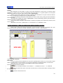
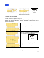
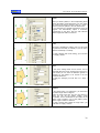
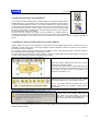
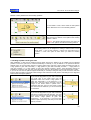
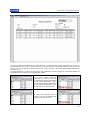
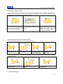
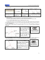
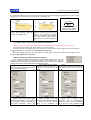
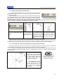
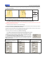
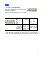
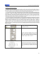
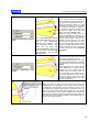
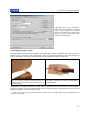
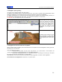
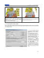
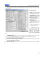
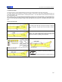
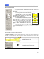
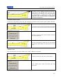
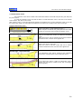
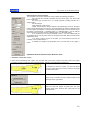
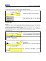
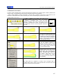
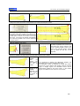
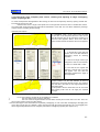
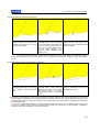
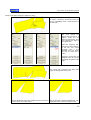
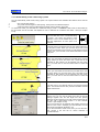
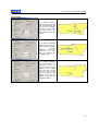
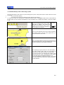
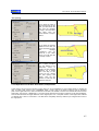
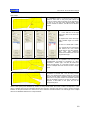
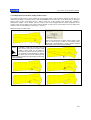
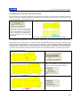
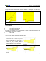
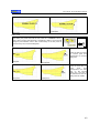
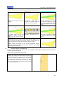
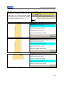
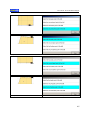
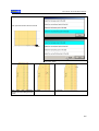
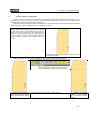
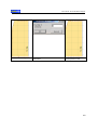
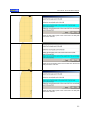
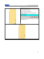
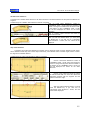
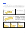
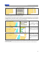
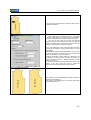
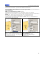
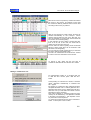
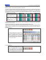
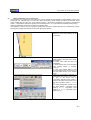
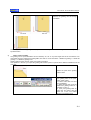
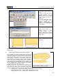
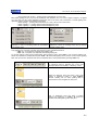
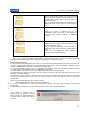
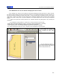
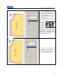
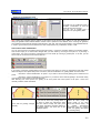
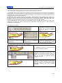
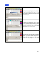
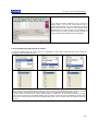
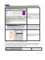
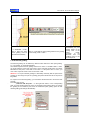
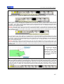
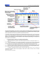
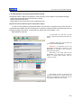
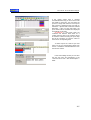
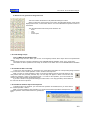
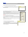
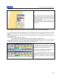
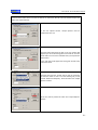
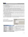
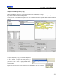
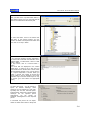
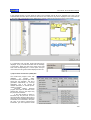
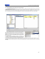
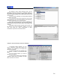
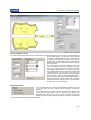
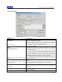
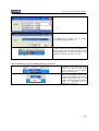
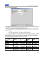
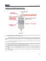
User manual - EuroCAD Pattern Designer
If the quotes values have a constant
increase/decrease step you don’t need to edit
the values for each size. You must enter the
quote for a single size and then set the quote
step, near the « Dimension step » and click on
the button: « Spread with a value the selected
dimension ». After you click this button, the
quote values will be calculated and displayed
automatically for all sizes.
ATTENTION: in case when sizes are
combined and between these sizes for a
certain quote the step is not constant, cannot
be used the method of writing the quote step
but will be necessary to input the value for
each size in corresponding field.
To delete a quote in a size set you must
select one of the corresponding values then
click on « Delete the selected dimension from
the size set » button.
In the same editing window you can enter
the size set name and description in the
« Size set name» and « Size set description »
fields.
265
User manual - EuroCAD Pattern Designer
1.12.3. Explaining the workspace in the parametrical mode
Generalities
IMPORTANT: in the parametrical mode you can only create and modify the anchorage parametrical layer. Over this
layer you must draw the patterns that will be anchored on the parametrical layer points by using the other design
methods in the program.
266
User manual - EuroCAD Pattern Designer
A. The workspace
The workspace is the area where the parametrical figures resulted from the design functions is displayed.
In the workspace you can visualize either the parametrical layer or the pieces layer or both layers superposed at
the same time. Mixing the parametrical and piece layers can be done by an interactive cursor « mix view » located in
the first button bar of EuroCAD Pattern Designer application. By mouse dragging on this cursor, you can switch the
two layers.
or
If you place the cursor in the
«- » position, only the piece
layer will be displayed.
You can also place the mouse
pointer over the cursor and right
click to open a menu from which
you
will
select
the
option
100%pieces-0%geometric in order
to display only the piece layer.
or
If you move the cursor toward
one of its ends (- or +) one layer will
become more visible than the other.
You can also place the mouse
pointer over the cursor and right
click to open a menu from which you
will select the option 100%pieces100%geometric in order to display
both layers
or
If you place the cursor in the
«+ » position, only the parametrical
layer will be displayed.
You can also place the mouse
pointer over the cursor and right click to
open a menu from which you will select
the option 0%pieces-100%geometric in
order to display only the parametrical
layer.
If you place the mouse cursor on a parametrical point, a
message will be displayed; it indicates the parametrical rule
used to create this point and the scenario step where it was
created.
267
User manual - EuroCAD Pattern Designer
B. Script area
The script area contains a table with the
steps of the parametrical design and 4
buttons by which you can add/delete the
steps in the list and by which you can
display/hide the design rules.
The table displays chronologically
the steps to be followed in order to
realize the parametrical design.
C. Geometrical operation description and editing area
This window contains the description of the selected function, a field to edit the values, the quote abbreviations,
the geometrical formulas (from simple to complex) and an area where the errors are displayed.
D. The quote list area
In this area there are displayed all the quotes introduced by the user in the “Edit size set” window in “GRADING”
mode and the measurements in the “Measurement table”.
The quotes added in the “Edit size set” window will appear here in green and the measurements in violet.
To use a measurement for the parametrical design, you must fill in the « Short » column in the “Measurement
table”. This column must contain an abbreviation of the measurement name. If this abbreviation is not entered, then it
will not be displayed in the quote list, so it cannot be used for the parametrical design.
The quotes and the measurements could be used easily to edit various functions of the parametrical design by a
simple selection or by completing the editing field in the description area, with the abbreviation of the selected quote.
When you drag the mouse over a quote in a list, its value for the selected size will be displayed with the current
measurement unit.
268
User manual - EuroCAD Pattern Designer
E. Buttons for the geometrical design functions
This area contains the buttons for all parametrical design functions.
When you drag the mouse pointer over a button, the associated function name will be
displayed. Moreover, on each button there is an icon that illustrates the specific function for
each button
The geometrical elements used by these functions are:
Point
Line
Circle
Control point
1.12.4 The design script
1.12.4.1 What is the design script
The design script is a list in which you can see, chronologically ordered, all the steps used for the parametrical
design.
The design script for a product is displayed in the «PARAMETRICAL DESIGN» mode, in the „Script Area”.
The buttons for all the operations in the script are located on the button bar in the «PARAMETRICAL DESIGN»
mode.
1.12.4.2 How to add a new step
To add a new step (operation) you must select one of the buttons that define the corresponding design functions
or you must click on the « Insert operation » button, located in the script area.
When you click on «Insert operation» button, a new step is added to the list and it will appear on the
next position after the previously selected step. The new step will appear in black in the list and will
contain the message « insert a new operation here ». To insert a new operation, you must choose and
click the button that represents the desired function.
If you click a button in the geometrical design functions area, a new step (operation) will be added at
the end of the list in the script area.
1.12.4.3 How to delete a step in the script list
To delete a step in the script list, you must select the operation to be deleted, then you must click on
the « Delete operation » button.
When you want to delete a step (operation) you will be warned that all operations that depend on the
selected operation will be deleted from the geometrical
layer.
269
User manual - EuroCAD Pattern Designer
1.12.4.4 Show/hide the rule for a step in the script
If you click on the « Draw all rules » button, in the workspace there will be displayed the design rules
used to obtain the geometrical elements (point, line, circle, Bezier curve).
If you click on the « Do not draw any rule » button, in the workspace there will be displayed only the
resulted geometrical elements (point, line, circle, Bezier curve); the design rules are not displayed.
To show/hide the design rule for a single step in the script, you must click on the corresponding box in
the « Draw » column of the script area. If the corresponding box is marked by an « X » then the design
rule for the selected step will be displayed; if that box is not marked by an « X », for the selected step it
will be displayed only the resulted geometrical element.
1.12.4.5 How to copy the script steps
To copy one or more steps in a script, you must first select the step in the « Script area » and the
click on the « Copy » button.
To select more steps in a script you must hold down the SHIFT key and click on the first and the last
step (for a continuous list selection) or you must hold down the CTRL key and click on each step to be
selected. To select all steps in a script, you must press CTRL+A key combination
To paste the copied step(s) in the script you must click to select the step over which you want to add
the clipboard content and then click on « Paste » button.
To delete the selected step and to copy it in the clipboard, you must click on « Cut » button.
1.12.4.6 Save or load a script
A project script can be saved on the computer hard disk or on a storage media (CD, zip, external
drive, SDcard) if you click on « Save script » button.
To load a script saved on the computer hard disk or on a storage media (CD, zip, external drive,
SDcard), you must click on the « Load script » button
1.12.4.7 What means the step colors?
Green
Red
Black
- indicates the script steps that determine the drawing of a geometrical element
- the steps marked in red has some parameters that are not defined yet
- marks a new inserted step for which there is no declared design function
270
User manual - EuroCAD Pattern Designer
1.12.5. Design functions
1.12.5.1 The list of the used design functions
1. Free point
2. point at X, Y from another point
3. Horizontal triangulation point
4. Vertical triangulation point
5. Point on a line at a given distance from another point
6. Point on a vector reported to horizontal axis
7. Point on a vector reported to another line
8. Point in the middle of a segment
9. Proportional point on a segment
10. Division points on a segment
11. Point on the perpendicular
12. Point on the median line
13. Perpendicular projection
14. Point by triangulation
15. Dart edge point
16. Point on a parallel line
17. Point at intersection
18. Point on the perpendicular line on a line with given angle
19. Edge point of the dart-angle
271
User manual - EuroCAD Pattern Designer
20. Two circles tangent points
21. Contact points of a tangent to a circle
22. Point at a given distance on a circle
23. Parallel to line
24. Point on tangent to circle
25. Point the center of a circle
26. Segment between two points
27. Line between two points
28. Circle defined by center and radius
29. Circle defined by center and contour point
30. Circle defined by diameter
31. Circle defined by three points
32. Circle defined by center point and circumference
33. Circle defined by contour and radius
34. Circle defined by center point and tangent to a specific line
35. Circle defined by center point and tangent to another circle
36. Circle with contour point and radius, tangent to a line
37. Circle with contour point and radius, tangent to a another circle
272
User manual - EuroCAD Pattern Designer
1.12.5.2 How to complete a function
To design a geometrical element, you must choose the design function and then you must edit its parameters. The
editing of the function parameters will be done in the « Description of the selected geometrical operation » area in the
spaces marked by red lines.
. When you click on the space
When you drag the mouse pointer over such region, the cursor will become a hand
underlined in red, that space will become underlined in blue; in the lower part of the « Description of the selected
geometrical operation » window will appear a field in which you may fill the value, the points, the quote or the formula
required to calculate the selected parameter.
To switch from a parameter to another you may press the Enter key or to select the function to be completed by a
mouse click.
Points
If one of the parameters in the function is a point (e.g.: point at X,Y from another point) and you want to edit such a
parameter, you must click to select the chosen point in the « script area»; alternatively, you must complete the full
name in the lower field in the « Description of the selected geometrical operation » window, and then you must press
the ENTER key to edit the next parameter.
To switch from parameter edit to another you can simply select another space to be completed instead pressing the
Enter key.
If the used function has a point as parameter and it is completed by selecting the point in the script area, you will not
need to press the Enter key, while the next space to be completed in that function will be selected automatically.
Values
If you want to edit a value for a specific parameter of the selected function, you must click on that parameter and to
complete the field in the lower part of the « Description of the selected geometrical operation » window with the
desired value.
Quotes
To use a quote or a measurement in the measurement table as parameter for a function, you can choose from two
options:
1. you may click on the space marked by a red line where you want to input the quote and you will edit by the
keyboard, in the lower field of the « Description of the selected geometrical operation » window the abbreviation for
that quote; then you must press the Enter key.
2. you may click on the space marked by a red line where you want to input the quote and then you must select
from the « quote list area » the desired quote; then you must press the Enter key.
! Attention The quotes used to edit a parameter must be of the same type with the parameters required for the
geometrical operation. For example, if you are using an angle quote for a length type parameter, you will be warned
by a message that appears under the field that edits the parameters of the selected function.
Distance between two points
The parameters for the design functions can be expressed as distance between two points. You must select the
space marked by red line where you want to enter the distance; then you must edit the points name, separated by
commas and between square brackets. The points name between which the distance will be calculated, can be
entered by selecting them from the « script area ».
E.g.: the distance between two points P1 and P2 will be edited as follows: [P1,P2]
If you want to display the distance between two points, you must drag the mouse pointer over that parameter in the
function and the value will be automatically displayed in a message.
Formulas
The parameters in a function can be edited as complex formulas that may contain values, quotes or distances
between points. To edit a formula, you must use the brackets.
If you drag the mouse pointer over a formula, its result will be automatically displayed.
273
User manual - EuroCAD Pattern Designer
1.12.5.3 Defining the design functions
1.
Free point
With the « Free point
» function, you can place a point anywhere in the
script area; this point does not depend on any other geometrical element. After you
select the function, you must click in the script area, where you want to place the free
point.
To start designing a garment, you must always start with a free point.
To change the position of a free point, you must select the specific step in the script, press on the SHIFT key and
click the left mouse button at the further point position.
For this function, there is no parameter to be completed in the « Description of the selected geometrical operation »
window.
2.
Point at XY from another point
This function will allow you to place a point on
horizontal « X » or on vertical
« Y » from an existing point. To assign the correct X and Y coordinates you must consider the
initial point as XY axis origin.
Assign parameters
To draw a new point by this function, you must assign
the following parameters:
- the starting point
- the horizontal distance (X)
- the vertical distance (Y)
If the reference point is already defined, you may hold down the SHIFT key and click the left mouse button at the
current position; the X and Y values are assigned from the screen and applied automatically in the operation text.
3.
Horizontal triangulation point
By this function you can draw a point Pn from
the point PA at a distance on
horizontal X and diagonal either upper or lower. In the near example, on the horizontal from
P1 point, at a distance X, it was raised the perpendicular line. On this perpendicular, it was
drawn the P2 point so as the distance between P1 n P2 will have the value D.
Function parameters
To draw a new point by this function, you must assign
the following parameters:
- reference point
- horizontal distance (X)
- diagonal distance (D)
You must also assign the placement direction for the
new point: up or down
If the reference point is already defined, you may hold down the SHIFT key and click the left mouse button at the
current position; the X and D values and the placement are assigned from the screen and applied automatically in the
operation text.
274
User manual - EuroCAD Pattern Designer
4. Vertical triangulation point
By this function you can draw a new point
Pn from an existing
point PA la at a distance on vertical Y and
on diagonal D.
In the near example, on the perpendicular from the P1 point you choose a point
at Y distance and trace the horizontal to the left or to the right. On this horizontal
you must choose a P2 point so as the P1-P2 distance to be equal with D.
The new point will be draw according to the specification „left” or „right” from the
reference point.
Function parameters
The function parameters are:
The reference points
Horizontal distance
The distance from the reference point
and the new point (D)
To draw the new point, you must define the left
or right direction
If the reference point is already defined, you may hold down the SHIFT key and click the left mouse button at the
current position; the Y and D values and the placement are assigned from the screen and applied automatically in the
operation text.
5. Point on a line at a given distance from another point
By this function you can obtain a new point on a line, placed at a
given distance from another point that is not on that line.
In the near example, the P4 point was added on the line defined
by P1 and P2 points, at a distance D from the P3 point, onto the
right side. The placement direction for the new point is reported
to the reference point (P3 in our example).
Function parameters
The function parameters are:
The points that define the line on which
the new point will be placed
The distance (D) from the new point
and the reference point
The reference point
To draw the point, you must also define the
direction, right or left.
Attention: the direction must be considered
starting from the reference point. To avoid
confusions, try first both variants, then choose
the correct direction.
6.
Point on a vector reported to horizontal axis
From the PA point, you draw a line at U° angle from horizontal ; on this line you
create a new point Pn at a distance D.
In the near example, from the P1 it was draw a line under U° angle from the
horizontal; on this line it was created a new point (P2) at a distance D from the
P1 point.
275
User manual - EuroCAD Pattern Designer
Function parameters
To draw a new point by this function, you must
assign the following parameters:
- reference point
- the angle from horizontal, measured in
degrees, U
- the distance between the reference point and
the new point (D)
If the reference point is already defined, you may hold down the SHIFT key and click the left mouse button at the
current position; the U and D values and the placement are assigned from the screen and applied automatically in the
operation text.
7. Point on a vector reported to another line
From the PA point a line is traced at a U° angle from a PB-PC line; on this
line a new point Pn is assigned at a distance D.
In the near example, from the P2 a line is traced at a U° angle from the line
defined by the P1 and P3 points; a new point P4 is created on this line at a
distance D from P2.
Function parameters
The function parameters are:
- reference point
- the line from which the vector is built
- angle from the line, measured in degrees, U
- the distance from the reference point and the
new point (D)
If the reference point is already defined, you may hold down the SHIFT key and click the left mouse button at the
current position; the U and D values and the placement are assigned from the screen and applied automatically in the
operation text.
8. Point in the middle of a segment
By this function you can draw a new point PN at
the middle
of the segment defined by the points PA and PB. In the near example, a new
point, P3, is placed at the middle of the segment defined by P1 and P2
points.
276
User manual - EuroCAD Pattern Designer
Function parameters
The function parameters are:
- reference points, represented by the points
that define the segment on which you place the
new point
9. Proportional point on a segment
By this function you can draw a new point PN on the
segment defined by the points PA and PB at a specific ratio
RP %. In the near example, a new point P3 is placed at a 30% ratio on the
segment defined by the P1 and P2 points. The ratio is considered from the
first declared point in the segment.
Function parameters
The function parameters are:
Reference points that
segment
The ratio, RP%
10.
Division points on a
defin
the
segment
By using this function, you can create a number N of new points,
evenly distributed (at equal distances) between the PA and PB points.
In the near example, between the P1 and P2 points, there were
placed 4 points (P3, P4, P5 and P6) evenly distributed.
Function parameters
The function parameters are:
Number of points N
The points between you want to place
the division points
277
User manual - EuroCAD Pattern Designer
11.
Point on the perpendicular
You can draw a new point, PN, at a distance D from the point PA on the
perpendicular from this point to the line defined by the points PB and PC.
Thus, you have defined the point P4 at a distance D form the point P3 on the
perpendicular from the point P4 to the line determined by P1 and P2.
Function parameters
The function parameters are:
The distance D
The point from which you calculate the
distance
The points that define the line on which
the perpendicular is built
12.
Point on the median line
You can draw a new point PN at a distance D on the
normal line
of the segment defined by points PA and PB.
A new point P3 is draw at a distance D on the normal line on the segment
defined by the P1 and P2 points. The distance is calculated on the left side of the
segment, as looking from the first point toward the second point.
Function parameters
The function parameters are:
- the points that define the segment
- the distance D between the new point and the
middle of the segment
13. Perpendicular projection
You can draw a new point PN as the perpendicular foot from the point
PA on a line defined by PB and PC points.
Thus you draw the point P4 at the intersection of the perpendicular
from the point P3 on the line defined by the points P1 and P2.
278
User manual - EuroCAD Pattern Designer
Function parameters
The function parameters are:
- the point from which starts the perpendicular
line
- the points that define the segment
14.
Point by triangulation
You can draw a new point PN at a distance DA from the point PA and at a distance
DB from the point PB
A new point P3 is defined, by triangulation from the points P1 and P2 at the
distances DA and DB respectively. The new point is defined on the left side as
looking from P1 toward P2.
Function parameters
To draw a new point by this function, you must
assign the following parameters:
- the point PA
- the point PB
- the distance DA between the new point and
the point PA
- the distance DB between the new point and
the point PB
To draw the new point you must define the left
or right direction.
Attention: To avoid confusions, try first both
variants then choose the correct direction.
If the reference points are already defined, you may hold down the SHIFT key and click the left mouse button at the
current position; the DA and DB values and the placement are assigned from the screen and applied automatically in
the operation text.
15.
Dart edge point
You must draw a new point PN that represents the dart edge end
that has the edge beginning in the point PA, the peak in the point
PB and the width D, either on the left or right side. The dart width
must be a positive number and must not overpass the double of the
distance between the points PA and PB
The point P3, that represents the edge end, was defined at a
distance D from the point P1 and the distance [P1,P2] equals the
distance [P2,P3].
279
User manual - EuroCAD Pattern Designer
Function parameters
To draw a new point by this function, you must
assign the following parameters:
- the point PA (the first dart edge - beginning)
- the point PB (the dart peak)
- the distance D (dart width)
- left/right option
Attention: To avoid confusions, try first both
variants then choose the correct direction.
16.
Point on a parallel line
From the point PA you draw a line that is parallel with the line PB-PC;
on this new created parallel line, you draw a new point Pn at a
distance D. The distance is calculated in the segment PB PC. If the
point PC is identical with the point PA then the new point is placed on
the line extension.
In the near example, from the point P3 it was drawn a parallel to the
line P1-P2; on this line, a new point P4 is created , at a distance D.
Function parameters
The function parameters are:
- Reference point PA
- the points that define the line between PB and
PC
- the distance D between the point PA and PN
17.
Point at intersection
You can draw a point at the intersection between the lines PA-PB and PC-PD
In the near example, the point P5 was placed at the intersection between P1P2 and P3-P4.
Function parameters
The function parameters are:
- the points PA and PB that define the fist line
- the points PC and PD that define the second
line
280
User manual - EuroCAD Pattern Designer
18.
Point on the perpendicular line on a line with given angle
You can draw a point (P3, in the near example) on the perpendicular on a line that is
placed at a defined angle from that perpendicular.
Function parameters
The function parameters are:
- the line angle
- the point to raise the perpendicular
- the points that define the line on which the
perpendicular is raised
19.
Edge point of the dart-angle
You can draw a new point PN that represents the end edge of a dart that starts in
the point PA, the peak in the point PB and the angle U to the left or right.
In the near example, in the point P1 you must draw a line at the angle U from the
line P1-P2 on the left/right side (on choice). You draw a point PN on this line, so
as the distance P3-P2 to be equal with the distance P1-P2.
Function parameters
The function parameters are:
- PA (the dart beginning edge)
- the point PB (the dart peak)
- the dart angle, U
- left/right option
281
User manual - EuroCAD Pattern Designer
20.
Two circles tangent points
You can draw the points PNA and PNB as contact points of the common
tangent to the circles CA and CB, either on the left or right side. A segment
PNA-PNB is drawn.
You have drawn the points P3 and P4 as contact points of the common
tangent on circles C1 and C2, either on the left or the right side
A segment P3-P4 was drawn.
Function parameters
The function parameters are:
- circle CA
- circle CB
- left/right option
21. Contact points of a tangent to a circle
You can draw a point PN as a contact point of the tangent line from the
external point PA on a circle CA either on the left or right side.
The point P3 is drawn on the tangent line in the point P2 on the circle C1 on
the left side.
Function parameters
The function parameters are:
- the circle CA
- the point PA
- left/right option
Attention: To avoid confusions, try first both
variants then choose the correct direction.
282
User manual - EuroCAD Pattern Designer
22. Point at a given distance on a circle
You can draw a new point PN at a distance D from the point PA located on the
circle CA and measures clockwise or counterclockwise.
In the near example, it was drawn the point P3 on the circle C1 at a distance D from the point P2, clockwise.
The distance must be always a positive number.
Function parameters
To draw a new point by this function, you must
assign the following parameters:
- the circle CA
- the point PA
- the distance D
- clockwise/counterclockwise option
23.
Parallel to line
You can build two new points PNA and PNB that define a parallel line at a
distance D from the line defined by the points PA and PB.
The points P3 and P4 define the parallel line to P1-P2, placed at a distance
D to the left or to the right side from the last selected reference point.
Function parameters
The function parameters are:
- the reference points that define the line from
which the parallel will be drawn
- the distance D
- left/right option
Attention: To avoid confusions, try first both
variants then choose the correct direction
24.
Point on tangent to circle
You can draw a new point PN at a distance D on the tangent in the point PA at
the circle CA, clockwise or counterclockwise.
The point P3 was placed at a distance D on the tangent in the point P2 at the
circle C1.
283
User manual - EuroCAD Pattern Designer
Function parameters
The function parameters are:
- the circle CA
- the point PA
- the distance D to be measured on the tangent
- clockwise/counterclockwise option
25.
Point the center of a circle
You can draw a new point PN in the center of a circle CA.
The point P3 was placed in the center of the circle C1.
Function parameters
The function parameters are:
- the circle CA
26.
Segment between two points
You can build a segment between two points PA and PB.
In the near example, between the points P1 and P2, a segment was drawn
Function parameters
The function parameters are:
- the points that define the segment
284
User manual - EuroCAD Pattern Designer
27. Line between two points
You can draw a line defined by two points PA and PB.
A line is defined by the points P1 and P2 .
Function parameters
The function parameters are:
- the points that define the segment
28.
Circle defined by center and radius
You can draw a new circle CN with the center in the point PA and R radius.
The circle C1 was defined by the center P1 and the radius R.
Function parameters
The function parameters are:
the point Pa – the circle center
the radius R
If the circle center is defined, you can hold the SHIFT key and the radius R value is assigned from the screen and
applied automatically in the operation text.
29.
Circle defined by center and contour point
You draw a new circle CN with the center in the point PA and that crosses
through the point PB on the contour.
The circle C1 was defined so as the point P1 represents its center and the
point P2 is on the contour.
285
User manual - EuroCAD Pattern Designer
Function parameters
The function parameters are:
- the point PA (circle center)
- the point PB (on the contour)
30.
Circle defined by diameter
You draw a new circle CN whose diameter is represented by the
segment defined by the points PA and PB.
The circle C1 was defined by the diameter represented by the segment between the
points P1 and P2.
Function parameters
The function parameters are:
- the point PA (circle center)
- the point PB (on the contour)
31.
Circle defined by three points
You draw a new circle CN that crosses through PA, PB and PC.
The circle C1 crosses through the points P1, P2 and P3.
Function parameters
The function parameters are:
- the points PA, PB and PC on the circle contour
286
User manual - EuroCAD Pattern Designer
32.
Circle defined by center and circumference
You draw a new circle CN with the center in the point PA and the circumference CIRC.
In the near example the circle C1 was defined with the center in the point P1 and with
circumference CIRC.
Function parameters
The function parameters are:
The point PA that is the circle center
The circle circumference - CIRC
33.
Circle defined by contour points and radius
You draw a new circle CN that crosses the points PA and PB and has
the radius R.
The circle C1 was defined so as it crosses the points P1 and P2 and has the radius R.
Function parameters
The function parameters are:
- the point PA
- the point PB
- the radius R
- the left/right option
If the two points on the contour are defined, you can hold the SHIFT key and the radius R value is assigned from the
current mouse position and applied automatically in the operation text.
34. Circle defined by center point and tangent to a specific
line
You draw a new circle CN with the center in the point PA and that is tangent to the
line defined by the points PB and PC.
In the near example, it was defined the circle C1 with the center in the point P1 and
tangent to the line defined by the points P2 and P3.
287
User manual - EuroCAD Pattern Designer
Function parameters
The function parameters are:
- the point PA, the circle center
- the points that define the line tangent to the
circle.
35.
Circle defined by center point and tangent to another circle
You draw a new circle CN with the center in the point PA and that is tangent to
the circle CA.
In the near example it was defined the circle C2 with the center in the point P2 so it will be
tangent to the circle C1.
Function parameters
The function parameters are:
- the point PA, the circle center
- the circle CA
36.
Circle with contour point and radius, tangent to a
line
You draw a new circle CN that crosses through the point PA, is tangent on the line
defined by the points PB and PC and has the radius R.
In the near example, the circle C1 was defined so as the point P1 is placed on its
contour, it has the radius R, and the points P2 and P3 define a tangent to the circle C1.
Function parameters
The function parameters are:
- the point PA on the circle contour
- the points PB and PC that define the tangent to
the circle
- the radius R
- the left/right option in order to place the circle
center from the point PA on the contour
Attention: To avoid confusions, try first both
variants then choose the correct direction
288
User manual - EuroCAD Pattern Designer
37.
Circle with contour point and radius, tangent to
another circle
You draw a new circle CN that crosses the point PA, is tangent to the circle CA and has
the radius R.
In the near example it was defined a circle C2 with radius R that has the point P2 on the
contour. The circle C2 is tangent to the circle C1.
Function parameters
The function parameters are:
- the point PA
- the circle CA
- the radius R
- the left/right option that will place the circle
center aside from the point PA on the contour
Attention: To avoid confusions, try first both
variants then choose the correct direction
1.12.6 Draw a pattern and anchor to the parametrical layer
By the parametrical design there are defined the positions of the important geometrical points in a pattern. Then, the
designer must draw by the direct method a pattern and anchor it on the points that are parametrically defined.
Concluding, after defining the main geometrical points, a pattern must be designed on the overlay; the pattern points
will be anchored on the geometrical points that have been already defined.
To do this, you must check first that you are displaying either the parametrical layer or the piece layer. To display
both layers, the interactive cursor « mix view » in the button bar in the « Parametrical design » mode MUST NOT be
placed on « -» or on « +» . To get from a layer to another, you must click the left mouse button on the cursor and drag
toward one of the edges.
1.
To draw a pattern anchored to the parametrical layer you have two options:
You can freely draw a pattern whose points will be anchored later on the geometrical layer in the « SHAPE TOOL »
mode
2.
You can directly anchor the points on the pattern to the points on the geometrical layer, during the design
process.
289
User manual - EuroCAD Pattern Designer
1.12.6.1 Free draw and anchoring the pattern point by point
a)
In the « DRAW TOOL » mode you must click on « Draw free or assisted
(with points and lines)» button in order to freely draw a pattern that approximately
follows the desired shape.
b) In the « SHAPE TOOL » mode you must select the pattern point by point. For each point of the drawing you must
define the geometrical dependence point and you must define the position of the designed
point from the dependent geometrical point.
To do this, you must first select the point and in the right side menu, at the « Point
definition » you must select the option « geom point » and in the field under you must
enter the name of the geometrical point on which the designed point will be anchored.
To superpose the designed point on the geometrical point, the values for the point position
must be zero.
Attention: After defining the geometrical point on which depends the designed point, you
must check and modify the position of the designed point.
For a faster position definition, you must get the drawing closer to the geometrical sketch;
then, in the « SHAPE TOOL » mode you must select the piece point by point, and by
using the ALT and SHIFT keys you can easily drag the piece points over the geometrical
layer points.
c) To finalize the pattern shape, you must follow the same steps as for the direct design
(transform lines to curves, define angles etc)
1.12.6.2 Direct anchoring during a pattern design
You can draw and anchor simultaneously the points designed on the
geometrical points, by magnetization.
In the « DRAW TOOL » mode you must click on « Draw free or
assisted (with points and lines)» button and hold the ALT +SHIFT
combination; then you must click on the geometrical points where you want
to anchor the designed points.
290
User manual - EuroCAD Pattern Designer
When you hold the ALT +SHIFT key combination, the points will be magnetized; this means that the designed
points will be precisely overlapping on the chosen geometrical points.
To finalize the pattern shape you must follow the same steps as for the direct design (transform lines to curves,
define angles etc)
1.12.7. How to adapt a direct designed product for automatic grading
For the preexisting models that were created by direct design or by digitization, you can create a simplified
parametrical anchoring system, used only for automatic grading. Thus, you can use the benefits of the automatic
grading either on products that were not created by parametrical design.
To do this, you must create a simple geometrical structure, usually rectangular, on which you must create, for
example, only points of type: center upper face, center down face, waist point, hip point, point shoulder to neck, point
shoulder to recess, etc. These points are created in a blink of an eye (usually by geometrical functions type XY, see
chapter 5.3 design function 2). Basically, the newly created geometrical points (based on the quotes in the size set)
should overlap the corresponding points on the base pattern, if the quote table is respected. The corresponding
points on the base pattern can be associated to these geometrical points. Their grading is borrowed with the
geometrical points movement.
IMPORTANT: if the position of the geometrical points that are created based on the quotes does not correspond
to the point position on the pattern, it means that there is an error either on the original pattern (that does not respect
the quotes in the table) or while you design the geometrical point; another reason can be the ignorance of the seam
allowance or of other technological adds.
The near examples show how the grading of trouser or skirt was transposed on the parametrical layer.
291
User manual - EuroCAD Pattern Designer
1.12.7.1 How to adapt a direct designed pant for automatic grading
To automatically grade a pant that was designed directly in EuroCAD
Pattern Designer, you must enter the PARAMETRICAL mode and create
a rectangular structure from the center face, mid-face, mid-back, lateral,
thigh and hip points together with the edge point on the pant.
Before starting the parametrical design, you must declare the size set and
the quotes required for this project (see chapter 2) or you can load an
already saved size set.
In the near example, you can see how to adapt a pant obtained by
direct design; we have considered a size set from 42 to 48 with the
following dimensions: body length, waist length, hip length, pant out seam,
pant inseam, pant wide on edge.
After entering the size set, you must mix the
parametrical and the piece layers, by the interactive
« mix view » cursor; thus you must have the
parametrical layer in front and you click the
« GEOMETRIC » button.
Parametrical design for the front piece:
1. You must create the free point P1 by a click on the « Free point » button this point will be defined as the front mid
point from the waist.
2. You must define the point P2 by a click on the « point at XY from another point »
button and represents the lateral point from the waist. This point is created at a distance
x = Pt/4 and y = 3 (cm) from the point P1.
Pt=waist length
3. You must define the point P3 by a click on the « point at XY from another point »
button and represents the slit point. This point is created at a distance x = -0,37 and y = 6,22 (cm) from the point P1.
4. You must define the point P4 by a click on the « point at XY from another point »
button and represents the hip point. This point is created at a distance x = Ps/4-1 and y =
0 (cm) from the point P3.
(Ps=hip length)
5. You must define the point P5 by a click on the « point at XY from another point »
button and represents the edge point. This point is created at a distance x = -0,2 and y =
-Lxp (cm) from the point P2
Lxp=the pant out seam
6. You must define the point P6 by a click on the « point at XY from another point »
button and represents the inseam thigh point. This point is created at a distance x = -Lpt
and y = 0 (cm) from the point P5.
Lpt= pant width on bottom, Lip = pant inseam
292
User manual - EuroCAD Pattern Designer
7. You must define the point P7 by a click on the « point at XY from another point » button and represents the hip
point. This point is created at a distance x = Ps/4-1 and y = 0 (cm) from the point P5
Lpt= the pant width at bottom
After you have created the points, you must display both parametrical and piece layer, by using the « mix view »
interactive cursor; thus, both layers will be displayed.
In the previous example, the pant was designed for the size 42. If the pieces in the model were designed for another
size, you must enter the GRADING mode and, in the right side menu, to check the corresponding measure for the
designed model. If the measure checked as base size in the GRADING mode does not correspond to the base size
for the designed model, the correct layer overlapping will fail.
In PIECE mode, you must select the front piece, and then you must click to select the front mid-point; then you must
drag the selected point to overlap the point P1 of the parametrical design ; during dragging, you must hold the
SHIFT+ALT key combination in order to magnetize these points.
If you hold the SHIFT+ALT key combination, you can magnetize the selected points to be overlapped (a guided
overlapping) on the chosen geometrical points.
If the piece points are overlapping on all geometrical points of the parametrical design then in the SHAPE TOOL
mode, you must select all the points of the designed piece and by holding the SHIFT+ALT combination, you will
magnetize the piece points over the corresponding points in the parametrical layer.
If the piece points are not overlapping on the points of the parametrical design, and you need an automatic grading
process and to preserve the shape of the designed piece, you must proceed as follows: in the SHAPE TOOL mode
you must select each point on the piece, while in the right side menu, on the « Point definition » field you must check
the « geom. point » message; in the field under this message you must enter the name of the geometrical point on
which you will anchor the piece point.
After the main points in a piece were anchored on the parametrical layer, the piece will be automatically graded and
the grading will be displayed if you click on the « Show/hide grading ».
Parametrical design for the back piece:
1. You must create the free point P8 by a click on the button « Free point »; this point will be defined as, back mid
point from the waist.
2. You must create the point P9 by a click on the « point at XY from another point »
button and represents the lateral edge point. This point is created at a distance x = 3,42
and y = -Lxp (cm) from the point P8.
Lxp=pant out seam
3. You must create the point P10 by a click on the « point at XY from another point »
button and represents the hip point. This point is created at a distance x = -0,3 and y = [P2, P4] (cm) from the point P8.
[P2,P4]=segment length defined by the points P2 and P4
4. You must create the point P11 by a click on the « point at XY from another point »
button and represents the back mid point from waist. This point is created at a distance
x = 4,11 and y = Pt/4 (cm) from the point P8.
Pt=waist length
5. You must create the point P12 by a click on the « point at XY from another point »
button and represents the point on the hip line – mid-back. This point is created at a
distance x = Ps/4+0,5 and y = 0,5 (cm) from the point P10.
Ps=hip length
6. You must create the point P13 by a click on the « point at XY from another point »
button and represents the internal end point. This point is created at a distance x =
Lpt+2,5 and y = 0 (cm) from the point P9
Lpt= pant bottom width
7. You must create the point P14 by a click on the « point at XY from another point »
button and represents the interior hip point. This point is created at a distance x = 2,87
and y = Lip(cm) from the point P9.
Lip = pant inseam
293
User manual - EuroCAD Pattern Designer
After you have created the points, you must display both parametrical and piece layer, by using the « mix view »
interactive cursor; thus, both layers will be displayed (parametrical and pieces). In « Piece » mode you must select
the back piece and click on the back mid-point ; then you must drag to overlap the point P8 of the parametrical design
by holding the SHIFT+ALT key combination in order to magnetize these points.
You must anchor next the other points of the piece at the parametrical layer. After anchoring on the parametrical
design, the piece is automatically graded ; the grading can be displayed or hidden by click on the « Show/Hide
grading » button.
Parametrical design for the waist band:
Front waist band
1. You must create the point P15 by a click on the « point at XY from another point » button and represents the side
blend point with the front. This point is created at a distance x = Pt/4-0,2 and y = 5,4(cm) from the P1 point.
Pt=waist length
2. You must create the point P16 by a click on the « point at XY from another point » button and represents the midupper point for the front waistband. This point is created at a distance x = 0 and y = 5(cm) from the point P1.
3. You must create the point P17 by a click on the « point at XY from another point » button and represents the lateral
upper point for the front waistband. This point is created at a distance x = Pt/4-2,2 and y = 4,9(cm) from the point
P16.
Pt=waist length
Back waistband
4. You must create the point P18 by a click on the « point at XY from another point » button and represents the midupper point for the back waistband. This point is created at a distance P11 at x = 0 and y = 5 (cm) distance from the
point P11.
5. You must create the point P19 by a click on the « point at XY from another point » button and represents the side
blend point with the back. This point is created at a distance x = -Pt/4+0,4 and y = 2,2(cm) from the point P11.
Pt=waist length
6. You must create the point P20 by a click on the « point at XY from another point » button and represents the side
upper point for the back waistband. This point is created at a distance x = -Pt/4+2,45 and y = 5+1,8cm) from the point
P11.
Pt= waist length
You must anchor the points on the front and back waistband pieces (left/right) on the corresponding points of the
parametrical design (similar to the front and back pieces anchoring). After anchoring on the parametrical design, the
pieces are automatically graded; the grading can be displayed or hidden by click on the « Show/Hide grading »
button.
294
User manual - EuroCAD Pattern Designer
1.12.7.2 How to adapt a direct designed skirt for automatic grading
To automatically grade a pant that was designed directly in EuroCAD Pattern Designer, you must enter the
PARAMETRICAL mode and create a rectangular structure from the mid point front, mid-point back, lateral points,
thigh point, hip point and points for skirt bottom.
Before starting the parametrical design, you must declare the size
set and the quotes required for this project (see chapter 1.12.2) or
you can load an already saved size set.
In the near example, you can see how to adapt a skirt obtained by
direct design for automatic grading; we have considered a size set
from 42 to 48 with the following dimensions: body length, waist
length, hip length, skirt side seam and bottom
After entering the size set, you must mix the parametrical and
the piece layers, by the interactive « mix view » cursor; thus
you must have the parametrical layer in front and you click the
« GEOMETRIC » button.
Parametrical design for the front piece:
1. You must create the point P1 by a click on the « Free point »
button this point will be defined as the front mid point from the
waist.
2. You must create the point P2 by a click on the « point at XY from another point
» button and represents the point on the product hemline from the center front.
This point is created at a distance x = 0 and y = -Lpr+1 (cm) from the point P1.
Lpr=product length
3. You must create the point P3 by a click on the « point at XY from another point
» button and represents the point on the product hemline from lateral. This point
is created at a distance x = -Ps/4-3.7 and y = 1 (cm) from the point P2.
Ps=hip length
4. You must create the point P4 by a click on the « point at XY from another point
» button and represents the center point from hip line. This point is created at a
distance x = 0 and y = -Ls+1 (cm) from the point P1.
Ls=hip length
5. You must create the point P5 by a click on the « point at XY from another point
» button and represents the hip point. This point is created at a distance x = Ps/4+ 0.5 and y = 0 (cm) from the point P4.
Ps=hip length
6. You must create the point P6 by a click on the « point at XY from another
point» button and represents the lateral hip point. This point is created at a distance x = -Ps/4-0,5-1,38 and y = 1,33
(cm) from the point P1.
Ps=hip length
7. You must create the point P7 by a click on the « point at XY from another point » button and represents the first
point of the front dart. This point is created at a distance x = -Pt/8 and y = 0 (cm) from the point P1.
Pt=waist length
295
User manual - EuroCAD Pattern Designer
8. You must create the point P8 by a click on the « point at XY from another point » button and represents the second
point on the back dart. This point is created at a distance x = -1,38 and y = 0 (cm) from the point P7.
9. You must create the point P9 by a click on the « point at XY from another point » button and represents the peak of
the front dart. This point is created at a distance x = -Pt/8 - 0,5 and y = -10 (cm) from the point P1.
Pt=waist length
After you have created the points, you must display both parametrical and piece layer, by using the « mix
view » interactive cursor; thus, both layers will be displayed (parametrical and pieces).
In the previous example, the skirt was designed for the size 44 and after entering the size set it remained
selected the base size 42. You must enter the GRADING mode and select the base size 44.
In PIECE mode, you must select the front piece, and then you must click to select the front mid-point; then you
must drag the selected point to overlap the point P1 of the parametrical design ; during dragging, you must hold the
SHIFT+ALT key combination in order to magnetize these points.
If you hold the SHIFT+ALT key combination, you can magnetize the selected points to be overlapped (a
guided overlapping) on the chosen geometrical points.
If the piece points are overlapping on all geometrical points of the parametrical design then in the
SHAPE TOOL mode, you must select all the points of the designed piece and by holding the SHIFT+ALT
combination, you will magnetize the piece points over the corresponding points in the parametrical layer.
If the piece points are not overlapping on the points of the parametrical design, and you need an automatic
grading process and to preserve the shape of the designed piece, you must proceed as follows: in the SHAPE TOOL
mode you must select each point on the piece, while in the right side menu, on the « Point definition » field you must
check the « geom. point » message; in the field under this message you must enter the name of the geometrical point
on which you will anchor the piece point.
After the main points in a piece were anchored on the parametrical layer, the piece will be automatically
graded and the grading will be displayed if you click on the « Show/hide grading ».
Parametrical design for the back piece:
1. You must create the free point P10 by a click on the « Free point » button; this point will be defined as the back mid
point from the waist.
2. You must create the point P11 by a click on the « point at XY from another point
» button and represents the point on the hemline from center back. This point is
created at a distance x = 0 and y = -Lpr (cm) from the point P10.
Lpr=product length.
3. You must create the point P12 by a click on the « point at XY from another point
» button and represents the point on the hemline from lateral. This point is created
at a distance x = -Ps/4-3.5 and y = 1 (cm) from the point P11.
Ps=hip length
4. You must create the point P13 by a click on the « point at XY from another point
» button and represents the waist point from lateral. This point is created at a
distance x = -Pt/4-1,5 and y =-0,5(cm) from the point P10.
Pt=waist length
5. You must create the point P14 by a click on the « point at XY from another point
» button and represents the center back point on the hip line. This point is created
at a distance x = 0 and y = -Ls (cm) from the point P10.
Ls=hip length
6. You must create the point P15 by a click on the « point at XY from another point » button and represents the hip
point. This point is created at a distance x =-Ps/4-0,5 and y = 0(cm) from the point P14.
Ps=hip length
7. You must create the point P16 by a click on the « point at XY from another point » button and represents the first
point at the back dart. This point is created at a distance x = -Pt/8 + 1 and y = 0 (cm) from the point P10.
Pt=waist length
296
User manual - EuroCAD Pattern Designer
8. You must create the point P17 by a click on the « point at XY from another point » button and represents the
second point of the back dart. This point is created at a distance x = -1,5 and y = 0 (cm) from the point P16.
9. You must create the point P18 by a click on the « point at XY from another point » button and represents the peak
of the back dart. This point is created at a distance x = -Pt/8 + 0,3 and y = -9 (cm) from the point P10.
Pt=waist length
After you have created the points, you must display both parametrical and piece layer, by using the « mix
view » interactive cursor; thus, both layers will be displayed. In the « Piece » mode you must select the back piece
and click on the back mid-point ; then you must drag to overlap the point P10 of the parametrical design by holding
the SHIFT+ALT key combination in order to magnetize these points.
You must anchor next the other points of the piece at the parametrical layer. After anchoring on the
parametrical design, the piece is automatically graded ; the grading can be displayed or hidden by click on the
« Show/Hide grading » button.
1.12.8 Getting a size set for a model that was created by parametrical design
If you want to create models for a new size set and you already have a size set for those models, you don’t have to
define a new parametrical layer. You just have to load the new size set and the model will be automatically
redimensioned and graded, so as it will correspond to the new quotes.
For a correct transfer, the new size set MUST contain the quotes used in the first step and must have the same
abbreviations (short names).
To load a new size set, you must enter the GRADING mode and click on the « Edit size set » button in the button bar.
In the opened window, you must click on the « Load a size set from file » button and then you must select the new
size set and click on the « OK » button.
How to add a size in the « Edit size set » in “GRADING” mode
In GRADING mode you must click on the button
„Edit size set”.
In the „Edit size set” window, in the button bar, you
must select the „Load a size set from file(F2)”
button, in order to open the window to select the
size set.
In the « Size set selection » window you must
choose the path on the hard disk and the file that
contains the size set to be loaded.
Here you can preview the sizes in a size set, their
name and details.
After you select the size set you must click on the
« Accept » button.
297
User manual - EuroCAD Pattern Designer
In the « Edit size set » window, the new size set is
loaded together with the new quotes. When you
click on the « Accept » button, the pieces in the
project are regarded according to the new size set
and the new quotes.
By the simple size set loading, the project will be
resized and graded so as it will correspond to the
new quotes.
1.12.9 „Made to measure” size – How to create an atypical size or the work on demand
-
For any model created by parametrical design you can automatically create a new size that will correspond to atypical
quotes that cannot be found in the loaded size set. This represents a major advantage mainly for the work on
demand.
Thus, the EuroCAD user will have only to input the client dimensions and its size will appear automatically near the
previous existing sizes.
To input the new size you have two methods:
you may add a size in the „Edit size set” and its settings as „Made to measure‘ size“
you may declare a preexisting size in the size set as „Made to measure‘ size“. Then, you must enter the
PARAMETRICAL mode and click on the „Quickly modify the dimensions from the size set for the client size” button in
order to open a table where you must input the dimensions for the new size.
In GRADING mode, you must click on « Edit size
set » on the button bar of this work mode. In the
opened window, you must click on the « Add a new
size » button or « Add a new grade size ».
In the window that appears you must introduce a
name for Made to Measure size and a index.
Attention! For Made to Measure the size index will
indicate only the position in size set. The index has
no influence on gradings. In made to measure
module only the dimensions will indicate the grading
step.
298
User manual - EuroCAD Pattern Designer
After a new column is added you must check the
« Made to measure‘ size » option.
The « Made to measure » size will be marked in red
(color that you cannot edit anymore).
Any size in the size set can be declared as ‘made to
measure’ size.
The quotes in a size can be modified also in the
table « Edit size set ».
In the PARAMETRICAL mode, you must click the
„Quickly modify the dimensions from the size set for
the client size” button.
In the opened table, you must enter the dimensions
for the special customer.
After you input the new values, you must click the
„Accept” button; it will result automatically the pattern
that corresponds to the new entered dimensions.
If you want to discard the new entered values you
must click on the „Cancel” button.
299
User manual - EuroCAD Pattern Designer
If in the size set it was not declared any size set as
‘made to measure’ size, when you click on „Quickly
modify the dimensions from the size set for the client
size” button in the PARAMETRICAL mode, a
warning message will be displayed.
If you want to use a size in the size set as made to
measure’ size, you must click on „Yes”. Otherwise
you must click on „No”.
If you have decided to use an existing size in the
size set as „made to measure” size, you must check
in the opened list the size whose quotes were
modified according to the customer dimensions.
After you have selected the size you must click on
„Accept” button. To cancel a size selection you must
click on „Cancel” button.
The new size will be added automatically to the
existing size set and will be colored in red.
300
User manual - EuroCAD Pattern Designer
1.12.10. How to create a classic skirt pattern in the Parametrical mode
Step 1. Define the quotes and the size set:
In the GRADING mode, you must click on the “Edit size set”
button; then you must input the size set and the quotes
required for the skirt pattern design.
Quotes required for designing a skirt pattern:
- waist length (C.t.)
- hip circumference (C.s.)
- hip length (L.s.)
- skirt width on hemline (L.t.)
- product length (L.pr.)
Step 2. Define and design of the geometrical points in the
Made To Measure module:
Before designing the geometrical points, you must display the
parametrical layer. To do this, you must get the interactive cursor « mix view » in the appropriate position (see
chapter 1.12.3 A).
P1- is a free drawn point ; you must click on the
« free point »button to create the point P1 that will be
considered as the mid-point on the back from the waist.
From this point, you must trace the waistline.
P2- point created by a click on the « point at XY
from another point » button. This point is created at a
distance x = 0 and y = -20 (cm) from the point P1. From this
point you must trace the hip line.
P3- point created by a click on the « point at XY
from another point » button. This point is created at a
distance x = 0 and y = -Lpr (cm) from the point P1. From this
point you must trace the hemline.
P4- point created by a click on the « point at XY
from another point » button. This point is created at a
distance de x = C.s.+ 1 and y = 0 from the point P2. This
point delimitates the mid front on the hip line.
P5- point created by a click on the « point at XY
from another point » button. This point is created at a
distance x = (C.s.+1)/2-1.5 and y = 0. from the point P2. This
point delimitates the front piece from the back piece on the
hip line.
P6- point created by a click on the « point at XY
from another point » button. This point is created at a distance x = 0 and y = 21 from the point P5. P6 is the point that
helps building the curves on the waist line.
P7- point created by a click on the « point at XY from another point » button. This point is created at a
distance x = -2.5 and y = 21 from the point P5.P7 represents the lateral front point from the waist line.
P8- point created by a click on the « point at XY from another point » button. This point is created at a
distance x = 2.5 and y = 21 from the point P5. P8 represents the lateral back point from the waist line.
P9 – is designed by a click on the « point at XY from another point » button. This point is created at a
distance x = C.t./4 and y = 0 from the point P1. The point P9 represents the peak of the first dart on the front piece.
P10 – designed by a click on the « point in the middle of a segment ». This is created at the middle of the
segment defined by the points P9 and P7. This point represents the peak of the second dart on the front piece.
P11- point created by a click on the « point at XY from another point » button. This point is created at a
distance x = 0 and y = -13,25 from the point P11. The point P11 helps you to create the first dart on the front piece.
This point is used to define the dart length.
P12- point created by a click on the « point at XY from another point » button. This point is created at a
distance x = 0 and y = -13,25 from the point P10. The point P11 helps you to create the first dart on the front piece.
This point is used to define the dart length.
-
-
-
301
User manual - EuroCAD Pattern Designer
-
-
-
-
-
-
-
-
-
P13,14- points created by a click on the « point at XY from another point » button. These points are created
at a distance x = -1,25 (for the point P13) and x = 1,25 (for the point P14) and y = -13.25 (for both points), from the
point P9. These two points defines the peak position of the first dart on the front piece.
P15, P16 - points created by a click on the « point at XY from another point » button. . These points are
created at a distance y = 0 and x = -1.25 for the point P16 and y = 0 and x = 1.25 for the P 16, from the point P15.
These two points defines the peak position of the second dart on the front piece.
P17- point created by a click on the « point at XY from another point » button. This point is created at a
distance x = C.s.+1 and y = 0 from the point P1. The point P17 represents the center of the back piece.
P18 - point created by a click on the « point at XY from another point » button. This point is created at a
distance x = -11 and y = 0 from the point P17. The point is located on the waistline and represents the peak of the
first dart on the back piece.
P19 - designed by a click on the « point in the middle of a segment ». The segment is defined by the points
P18 and P8. This point represents the peak of the second dart on the back piece.
P20 - point created by a click on the « point at XY from another point » button. This point is created at a
distance x = 0 and y = -8.8 from the point P19. This point helps you to define the second dart on the back piece and
gives its length.
P21,22 - points created by a click on the « point at XY from another point » button. These points are created
at a distance x = -1 and y = 0 for the point P21 and x = 1 and y = 0 for the point P22, from the point P18. These points
help you to create the first dart on the back piece and define the peak position.
P23,P24 - points created by a click on the « point at XY from another point » button. These points are
created at a distance x = 1 and y = 0 and x = -1 and y = 0 for the point P24. These points help you to create the
second dart on the back piece and define the peak position.
P25 - point created by a click on the « point at XY from another point » button. This point is defined from the
point P18 at the x = 0 and y = -8,8 coordinates. This point represents the length of the first dart for the back piece.
P26 - point created by a click on the « point at XY from another point » button. This point is defined at a
distance x = 0 and y = -L.pr from the point P25. P26 help to design the ends on the front and back pieces.
P27- point created by a click on the « Point by triangulation » button. This point is defined at a distance
„L.pr” from the point P7 and at a distance of 2 cm from the point P26 on the left side of the two points. This point is
found on the seam line on the front piece and defines the product length and width at end.
P28 - point created by a click on the « Point by triangulation » button. This point is defined at a distance
„L.pr” from the point P8 and at a distance of 2 cm from the point P26 on the right side of the two points. This point is
found on the seam line on the front piece and defines the product length and width at end.
P29- point created by a click on the « point at XY from another point » button. This point is defined at a
distance x = 0 and y = -L.pr. P29 helps to define the end on the back piece.
Step 3. Design and anchor the patterns to the parametrical layer:
In this step you must display the parametrical layer. To do this, you must get the interactive cursor « mix view » in the
appropriate position (see chapter 3.1 A).
To design and anchor the pieces at the parametrical
layer you must hold the SHIFT+ ALT combination key and to
draw after you have clicked the button « Draw free or
assisted (with points and lines) » in the DRAW TOOL mode.
If you hold the SHIFT+ALT combination key, you can
magnetize the points; this means that the designed points
will be precisely overlapping on the chosen geometrical
points.
302
User manual - EuroCAD Pattern Designer
To finalize the piece shape you must follow the same steps as for the classic design (transform some lines in
curves, define the angles, setting the seam allowance, define the grain axis, check the pieces, etc).
The patterns obtained by design and anchor to the parametrical layer are automatically graded according to the
quotes used in the size set table.
303
User manual - EuroCAD Pattern Designer
1.13 General functions in EuroCAD Pattern Designer
•
•
•
•
•
•
•
•
Beside design functions that are grouped in specific working modes, EuroCAD Pattern Designer offers general
functions assigned to the whole model or working mode:
Editing dependency points
Editing the product technical sheets
Printing the product and pieces technical sheets
Printing the patterns on plotter
Import / export the models in standard forms
Program work settings
Verification function for the patterns before cutting
Help files
The buttons for these functions are located on the button bar in the upper menu; these buttons are visible and active
in any working mode of the program.
1.13.1 Edit dependency groups for the pieces in a model
For an efficient marker when the model is designed on striped fabric, besides matching points, EuroCAD Pattern
Designer allows you to define dependencies between pieces. Now you will be able to realize an automatic marker
with alignment restrictions for other pieces.
This function supposes that the piece placement on maker should be defined from the design step. This piece
placement will be defined by the dependency groups between pieces, structured initially in dependency groups on
horizontal and vertical. Either in horizontal dependency group or in the vertical one, the pieces can be grouped in free
pieces, pieces aligned to stripe and plaid, or independent groups.
The pieces edited as free pieces can be placed anywhere on the marker.
If some pieces are set as pieces aligned to stripe and plaid, they will be placed with the matching point on the stripe
line of the horizontal or vertical group.
If two pieces are set as part of a group other than free pieces group or the group of pieces aligned to stripe and plaid,
those two pieces will be dependent only between them according to the matching point placement; the first piece can
be placed on any position on the marker and the second piece will be
placed according to the first one. For the double mirror pieces to appear
identical on the product, they have to be included in both horizontal and
vertical dependency groups.
To define dependency groups for the pieces in a model, click on « Edit
piece group dependency » button in the upper menu. Thus « Edit
dependency groups » window is opened.
304
User manual - EuroCAD Pattern Designer
In the left side of the « Edit dependency groups » window are displayed the horizontal and vertical dependency
groups and the pieces from these groups. To display the vertical dependent groups and the pieces inside them, click
on « Vertical » button. To display the horizontal dependent groups and the pieces inside them, click on « Horizontal »
button.
Initially, only « Free pieces » and « Aligned pieces to stripes and plaid» dependency groups are displayed and all
pieces in a model are part of the free pieces group.
To display the pieces in a dependency group, you must click on the small square with the « + » sign
near the dependency group name or you must click on « Show dependency group pieces » button in
the upper part of the
« Edit dependency groups » window.
To hide the pieces and display only the horizontal or vertical dependency groups, you must click on the
small square with the « - » sign near the dependency group name or you must click on « Hide
dependency group pieces » in the upper part of the « Edit dependency groups » window.
For the style with multiple fabric layers (de ex : fond, coating, insertion etc) you
can edit the dependency groups either for a single fabric or for all fabric layers.
Thus, you must use the filter near the message „Fabric”. You must click on the
small arrow on the right side of the box and must select from the displayed list
the fabric for which you will edit the dependency groups. When you select the
fabric in „Free pieces” group, only the pieces from that fabric will remain
displayed.
Dependency group between pieces.
If you want no nest the pieces between them, you may add one or more
dependency groups, other than the dependency groups for stripes and plaid.
If you want that the design on the face pocket to be continued on the product
face and if you don’t need that these pieces to respect some design specific
to the stripes and plaid, then you can create a dependency group only for
the face and the pocket. This group will be added to the horizontal/vertical
groups if you want to continue the design horizontally/vertically.
To add a new dependency group to the other two that are initially displayed,
click on the right mouse button in the « Edit dependency groups » window
and select « Add group »
A new window will open and you will be able to edit the name of the new
dependency group. After editing the name of the new group, click on « OK »
button for this group to appear near the others. If you want to quit the
creation of a new group, click on « Cancel » button.
To introduce or to delete pieces in a dependency group, you have to select the
piece and to drag it by the mouse in the desired group.
The unselected pieces or groups has the corresponding icons in yellow. When
these pieces or groups are selected, the icons become red.
305
User manual - EuroCAD Pattern Designer
ATTENTION
If you want the same design on double symmetrical pieces, then you have to assign these pieces in the same
dependency group, both on horizontal and vertical.
When you select a dependency group, in the right side of the « Edit dependency groups » window , the pieces in that
group will be displayed together with their matching points and the horizontal or vertical alignment according to
striped and plaid fabric.
Operations that can be done on a dependency group
If you click on the right mouse button on an added dependency group, it will
appear a menu with the following options:
- add group
- delete group
- rename group
If you want to add a new dependency group, click to choose ”Add group” option.
If you want to delete a dependency group, click to choose ”Delete group” option.
If you want to rename a dependency group, click to choose ”Rename group”
option.
If you want to a subgroup to the selected dependency group, click to choose ”Add
subgroup” option. A new window will open and you can enter the name for the
new subgroup to be added.
After you have established the dependency groups and the pieces inside each group, you must click on „Accept”
button in the lower right part of the « Edit dependency groups » window. If you want to cancel the creation of the
dependency groups, click on „Quit” button.
306
User manual - EuroCAD Pattern Designer
1.13.2 Edit the project technical sheets
The project technical sheet contains auxiliary information that goes together with the pattern and the drawing of the
final product. The purpose of these data is to identify and group the model according to model name, season, client,
order, designer and also to provide technical specifications regarding the product realization, indications on the fabric,
accessories, finishing process.
To edit the information in the product file, click on « Edit the project technical sheets ». The project technical sheet
editing window is opened and you can enter the needed information in the corresponding fields. In the project
technical sheet editing window, on the first page you can enter general information for the product; on the other two
pages you can enter drawings and technical specifications for a better description of the final product and the
technological process. To add an image of the final product or a technical drawing in the general information page,
click on « Download image » button. Choose the file for the piece picture or drawing. The file size must be under 500
kb. It is recommended that the images are on compressed formats as: *.jpeg, *.jpg, *.gif, *.wmf. The images can be
provided by a scanner or from drawing software. To use the pages with drawings and technical specifications, you
must first check the « Use this page with supplementary information » option. The drawings and technical
specifications pages are divided in 4 quadrants; in each of them you can insert text or images.
Edit the project technical sheets
Click on « Edit the project technical sheets »
button in the upper right side menu.
In the opened window, enter the information
related to the production in the corresponding
boxes. To add an image of the product file, click
on « Load image» button. The user can have a
preview of this picture when open the project.
In the project technical sheet there is an
“Attachments” field where you can attach any
type of files. The attached files can be visualized
only after they are saved ob the hard-disk and
they can be opened with the specific associated
programs.
The attached files must not be larger than 500
kb. To attach one or more files to a project, you
must click on the “Attach” button in the “Product
technical sheet”. In the opened window you
must select the files to be attached and then click
on OK button. To save one or more files that are
attached to the project on the hard-disk , you
must select the files and then click on the “Save
as…” button, then you must choose the save
path and click on the OK button.
To delete an attached file, you must select the file
and then click on the OK button
To save the entered information, click on
« Accept » button.
307
User manual - EuroCAD Pattern Designer
In the upper part of the Product technical
sheet window you must select the page
“Drawings and technical specifications”.
You must check the « Use this page with
supplementary specifications » box in
order to be able to edit the quarters in this
page.
In any of the two pages of drawings and
specifications you can enter text or image
information. To do so, click on the arrow
near the message “ Use: „ that can be
found over each quadrant in the page. A
menu will open with „Text” and „Image”
options; you can select the type of
information to be introduced. If you have
selected „Text” you will be able to enter
the specific text in the corresponding
quadrant. To save information, click on
« Accept »
If you have selected « Image » then two
specific buttons will automatically appear:
« Download image » and « Delete image
». To add an image, click on « Download
image » button. To save the entered
information, click on « Accept » button.
308
User manual - EuroCAD Pattern Designer
309
User manual - EuroCAD Pattern Designer
1.13.3 Print project and piece technical sheets
To print the project technical sheet, click on « Print project technical sheet » button. Click on the symbol on the right
side of the button; a small menu opens in which you can select three printing options: for product technical sheet, for
all pieces and for technical sheets of the selected pieces.
All technical sheets can be printed if you click on the upper main menu, on « Project » and then on « Print technical
sheets » in the opened submenu. Then click on the sheet type and the “Output Option” window will be opened. In ths
window you can choose to print, to preview or to save the technical sheets in PDF format. Print project and piece
technical sheets
To print the technical sheet, click on
« Print project technical sheet »
button, directly on the printer symbol.
To print the pieces technical sheets
click on the small symbol on the right
side of the « Print project technical
sheet » button.
A small menu opens in which you
can select three printing options:
for product technical sheet, for all
pieces and for technical sheets of
the selected pieces.
To preview the technical sheets
before printing click on the upper
main menu, on « Project » and then
on « Print technical sheets » in the
opened submenu.
In the preview window, the technical
sheet appears identical to the printed
form. You can use the upper buttons
to zoom in/out the image or to go to
next page.
If the technical sheet is correct
and ready to be printed, click on
« Print report » button. If you want
to cancel the printing process,
click on « Exit viewer » button.
To send in electronic format the technical sheets made by EuroCAD Pattern Designer, these must be converted
in PDF files. For this you must check “File” option from “Output Options”. After selecting “File” click on the arrow from
the “Format” field in order to choose the file type that user wants to save. From the following list you will choose
“Adobe Acrobat (PDF)” .To save a PDF you must press ok button from “Output Options” window.
310
User manual - EuroCAD Pattern Designer
To convert the marker report from EuroCAD Pattern Designer in PDF file, press “Print project
technical sheet” button which is on the the tool bar or select from the bar menu the function Project, the
option Print technical sheets.
In the new opened window, “Output Options” must be
checked the “File” box.
Click the button that shows the disk. In the new window that
appears you will set the saving path for the PDF file. Its name
will be edit in the “File name” field after that you will press the
“Save button”.
In the “File” field it will appear the saving path and file name
that will be saved.
Click the arrow from the “Format” field in order to choose the
file that user wants to save. From the following list you will
choose “Adobe Acrobat (PDF)” .Press ok button from “Output
Options” window.
At the end, will be pressed ok button from “Output Options”
window.
311
User manual - EuroCAD Pattern Designer
Printed product technical sheet example
Printed piece technical sheet example
1.13.4 Printing patterns on a plotter. RS274D file export
The pieces in the designed model can be directly printed on a plotter at 1: 1 scale, in order to be checked on shape
and dimensions or to generate a product based on this pattern. You can use a large wide plotter, e.g. for printing the
markers for cutting or a smaller plotter, under 1 m wide, in order to print the pieces one by one, according to the
printer working area.
To print the model on the plotter, you must first to select a piece to be printed. If you must print all pieces, you don’t
have to select any piece. The piece selection has to be done in « PIECE » mode. Hold down SHIFT key and click on
each piece to be selected. Selection can also be done by circling the pieces by a left click on the mouse and dragging
a contour around the pieces to be selected.
Click on « Export as PLT the selected files » button. The print on plotter
window will open. Here you must select what and how you want to print.
First, you have to check if the print paper size corresponds with the
program settings: if the paper width and length are properly set, then the
previsualization region on the screen will fit exactly with the print. These
settings must be checked in « Plotter settings » frame that opens when you click the « Settings » button in the
« Export format PLT » window.
312
User manual - EuroCAD Pattern Designer
•
•
•
•
•
The main plotter printing options are:
Pieces arrangement (unfolded or overlapped, with/without reserve between pieces)
Choose the sizes to be printed
Choose the piece elements to be printed (sewing line, cutting line, technical points, grain axis, name)
Choose the pieces to be printed (all pieces or only selected pieces)
Choose printing position (normal arranged pieces or rotated on 90°)
After checking the preferred options, click on the « Apply » button. The pieces will be displayed identical as they will
be printed on the plotter. Their arrangement has to avoid overlapping and paper wasting.
a. Piece arrangement
If you choose to arrange and realign overlapped pieces, you must exit the export window by clicking the « Quit »;
then enter the « PIECE » mode and arrange the pieces as you wish.
Click the button « Arrange pieces on the cut line » to automatically arrange pieces so as after adding the seam
allowance or after piece symmetrization to avoid piece overlapping. This button can be found on the first button bar of
EuroCAD Pattern Designer application.
313
User manual - EuroCAD Pattern Designer
In the printing window you can decide the pieces
arrangement. If you need the pieces to be printed
to overlap, you must check the corresponding box
For a better arrangement of the unfolded pieces, you must click on « Nesting
with EuroCAD Automarker » button in the « Export format PLT » window.
When you click this button, you will launch the EuroCAD Automarker
application. Here you will find the selected pieces; if you click the « Complete
automatic nest (time limit) » button, the pieces will be arranged. When the
pieces are placed in the ideal position, you must close the EuroCAD
Automarker application and in the preview area of the « Export format PLT »
window, the arranged pieces will be displayed, according to the result of piece
arrangement.
ATTENTION !: The optimization done by EuroCAD Automarker launched from EuroCAD Pattern Designer, does not
produce markers! The purpose of this optimization id only to arrange the pieces in order to avoid paper waste; thus,
the piece arrangement will not respect the piece properties and restrictions.
If you have checked the pieces to be unfolded,
you can also define the distance between the
pieces; enter the desired value in the field near
the message « Gap between pieces ».
The piece arrangement can be optimized by
EuroCAD Automarker application. Click on
« Nesting with EuroCAD Automarker » button to
launch the application through which the pieces
will be rearranged automatically or manually for
an optimal nesting.
b. Choose the sizes to be printed
You must check the size(s) to be printed. If there are more checked sizes, they will
be printed overlapped or unfolded, according to your choice regarding the piece
arrangement.
The value in the column « No » shows how many times will be printed the selected
size. For instance, when you choose to display the pieces as « unfolded » and you
select a size in the table, while in the “Pc” column you have inserted the value 2 and
then you have clicked on „Apply” button, then in the preview area, the pieces for the
selected size will appear twice.
If you check the message „Only base size”, in the table only the base size will be
checked automatically. If you uncheck this message, all sizes in the table will be
checked.
c. Choose the piece elements to be printed
In the “Export settings” area, you must check the piece elements to be printed. After
you check the elements to be printed, you must click the « Apply » button to display
the settings and to print them accordingly.
Text – if you check « Text », the piece name will be printed together with the
comments and size.
Only piece size - if you check this message, only the piece size will be printed
with the pieces.
Text added to piece name – The text entered in this field will be displayed and
printed together with the piece name.
314
User manual - EuroCAD Pattern Designer
Notches – if you check this message, the notches will be printed
Axes - if you check this option, all axes on the pieces will be printed (grain axis, text axis)
Only text for text axis – if you check this message, the text from the text axis will be displayed and printed,
without the corresponding axes. If not checked, the axes and the corresponding text will be printed only if the Axes
message is checked.
Internal points – if you check this option, the internal technical points will be printed.
Cut line - if you check this option, the pieces will be printed on the cut line.
Seam line – if the pieces to be printed are designed on the cut line, this option is invalid. if you check this option,
the piece will be printed on the seam line.
Unfolded folds - if you check this option, the pieces with folds will be displayed and printed unfolded.
Symmetrized - if you check this option, the symmetrical pieces with a declared symmetry axis will be displayed
and printed.
Auxiliary pieces – if you check this option, the auxiliary pieces will be printed together with the main piece.
d.
Choose the pieces to be printed
If you have selected only part of the project pieces but you want to print all
pieces, you must uncheck the message « Export only selected pieces ».
e. Choose printing position
If you work in “overlapped” mode, you can choose to print pieces as displayed or
rotated by 90 degrees.
f. Save plotter settings
For the users that have acquired more than one plotter type, you can save the plotter
settings on a separate list. Before printing, you must choose the plotter from the list.
After the result is displayed, you must click on the « Direct plot »
button if you want to print on a plotter or « Export PLT » if you
want to obtain a file with *.plt extension. If you need to print many
copies of the same drawing, then before clicking on the « Direct
plot » button, you must enter the number of copies in the box
near the message « Number of copies ».
If you click on « Export PLT » button, the program will save a file with *.plt extension on the hard disk.; this file can be
sent for printing to any other plotter. From this window you can also export files in RS274D format, when you click on
the « Export RS274D » button; these export files will have the CUT extension.
PLT files
PLT files can have various extensions as: *.plt, *.hpgl or without extension. These files can be used only to print
markers or pieces.
A piece shape cannot be changed from such a file. If the file contains a marker, you cannot modify or change this
marker.
When you print a HPGL/PLT file, you must check the piece dimensions, together with their length and width.
If you click on « Direct plot » button, you will obtain a PLT file that will be saved in the ACTIVE directory, from which it
will be automatically read by the EuroCAD PlotMaster application.
If you click on « Export PLT » button, you can also obtain a PLT file that can be saved anywhere on the hard disk and
that can be printed later or on another plotter.
315
User manual - EuroCAD Pattern Designer
CUT or RS274D files
CUT files can have the *.cut or *.gbr extension.
These files can be used only for automatic cutting machines or for printing.
CUT files for cutting machine contain only the cut line and the notches.
A piece shape cannot be changed from such a file. If the file contains a marker, you cannot modify or change this
marker.
If you cut or print a CUT file you must check the piece dimensions, together with their length and width.
1.13.5 DXF, Gerber, Assyst, Lectra or Investronica file type import
a. Import DXF and DXF-AMAA files
EuroCAD Pattern Designer program is able to import projects saved in DXF or DXF-AMAA format.
DXF files (Data Exchange files) are used for patterns only and contain pieces for each size.
DXF-AAMA files are accompanied by a RUL or TXT file. These DXF-AAMA files are used also for patterns only and
they include only the pieces on the base size. The grading rules for the pieces in a DXF–AAMA file can be found in
the RUL or TXT file.
The pieces in a DXF or DXF-AAMA file can be imported on the seam line or on the cut line but never on both.
Sometimes, the seam line can appear inside the piece but as auxiliary piece.
DXF and DXF-AAMA files does not include information regarding the piece number and the fabric used. In some
cases there is some information regarding the fabric type, but this information accuracy must be checked.
To import one of those file types,
you must click on « Import » option
in the « Project » menu. A submenu
will open; it contains the file types
that can be imported by EuroCAD
Pattern Designer. In this list you
must choose the file type to work
with. If you don’t know the DXF file
that will be imported, you must
choose the first option in the list
« DXF/AAMA (*.dxf) files». After
selecting the file type, it will open a
small window, similar to those that
opens for *.PAT files.
Explore the folder list up to you get the file to be opened. In the central window appears the file list in the selected
folder. Click on the file to be opened. If you have selected the correct file, in the right side window will be displayed
the project content. To open the selected project, click on « Accept » button. If the file content is not correct, on
screen appears « Invalid file » message together with a list of the encountered problems in the selected file.
316
User manual - EuroCAD Pattern Designer
When you import any DXF file you have the multiple file selection option; you can also open them in a single PAT file.
To select multiple files, hold down SHIFT key and left click on the first and last file to select all files between them. For
a random selection you must use the CTRL key instead.
If the imported DXF files have different size sets, only the pieces with different grading groups will be imported.
How to import in EuroCAD Pattern Designer - DXF/ AAMA file settings
After the user press “Accept” button, a new window will open, window called “Import DXF files” Here the user has
different options and settings to choose from.
You must select a measurement unit for the saved DXF file, together with the scaling factor.
317
User manual - EuroCAD Pattern Designer
If the message Import grading rules is unchecked at the DXF file import then each size of a piece will be imported
separately in EuroCAD.
If the message Import grading rules is checked, then EuroCAD Pattern Designer application will build the grading
table. When you import DXF files in which for each size corresponds a piece in a file, EuroCAD Pattern Designer will
automatically convert the piece sizes into grading table. Thus, after the import there will be no more pieces for each
size but only the base size and the corresponding grading.
For DXF-AAMA files, you must check the option « Import grading rules » in order to import the base size with all
grading rules. If this option is unchecked, the result will be represented by the base size only.
If for the DXF files this option is unchecked or if the gradings cannot be converted, the pieces can be imported
separately, one piece for each size with different grading groups.
The „Import only base size” setting is unchecked by default.
There are a few situations when the dxf file is exported in both ways: each piece as a simple size (as simple dxf)
and the base size and grading table in different files (as dxf aama file). In this case, to avoid importing pieces twice,
check the „Import only base size” together with the „Import grading rules” setting.
The grading will be first recreated using the existing pieces when both above mentioned settings are checked. If
the recreation succeeds, a single piece will be imported with corresponding grading. If the recreation doesn’t
succeeds, it will be imported also a single piece but the size set will contain a single size in this case (the size will be
called BS –the pattern will not be graded).
The option Import on the internal seam line must be checked according to the DXF creation method. If the file
includes the pieces on the seam line, you must check this option; if the pieces on the cut line, you must leave the
message unchecked.
Important pieces rearrangement can be done automatically if you check the message Rearrange the imported
pieces.
In order to import the internal drawings for the pieces in a DXF file, you must check the Import internal drawings
option.
If you check Round the pieces contour on DXF file import, part of the points on the piece contour will be smoothed.
Only the points whose smoothing does not coarsely affect the piece shape will be smoothed.
If you check Only curve points, on DXF file import only the points on the curve of the piece contour will be
smoothed. If you will checked the option “Use margin” then the contour of the imported pieces it will have a smooth
contour in the points with a deviation toward the initial position equal with the introduced value in the field of this
318
User manual - EuroCAD Pattern Designer
-
option. When is checked the option “Use special rounding algorithm” the contour of the pieces will be rounded after
the algorithm of drawing curves.
If you check Switch the sign of the grading rules the sign for the grading steps will be changed and the smaller
sizes in the set becomes larger sizes.
If the “Set name from annotation field” setting is checked then, the message from “Piece information” will be
added next to the piece name in the piece name field. If this option is unchecked then all the information are imported
only in the “Pattern information table”.
Attention: if in the window of preview pattern, the patterns don’t have name, there is a possibility that the
information referred to the name of the pattern to be found in the comments which are imported usually in “Pattern
information”. In this case is recommended to check the option “Set name from annotation field”
When the “Set points without grading to curve point” setting is checked, all grade points which don’t have
grading will be imported as curve points. It is used in case if the are points set as graded points, but don’t have
information about grading. Using this setting you can decide if those points will be keep as graded points, or will be
converted in curve points, so these points will be graded proportional to the grading of the nearest points. This
situation can be seen at the files which result from Lectra. The checking of the option “Smooth graded curve points”
will convert each curve point in smooth point. It is recommended only in case if in the file are few points and the piece
and the corners of the piece are cusp.
With the import function “ Files DXF/AAMA (*.dxf)” will be imported and the files created in AutoCAD/ Corel or
are imported files which imitate the original AutoCAD format. It is recommended that at the import of these files not to
be checked the option “Rearrange the imported patterns” in this way it is possible to correct easier the errors that
result from the different way of construction.
It is recommended that when you will import .dxf files that result from programs AutoCAD, CorelDraw etc. to be
tested alternative the standard DXF settings:
Use standard dxf format is checked when you know for sure if the file results from AutoCAD, or if you don’t
know the provenience of the file is unknown.
Use pattern reconstruction. Even if the pattern is imported in preview window, it is ok to test the import of t he
pattern and with this function. Major differences can be seen in case if the pieces are spread all around the file. By
using the option “Use detection margin” you can avoid the import of the patterns with the open contour. For
example these margins have very small values, 1- 2 mm and you don’t have to ignore it.
Information about DXF file
You can also preview some information regarding the
DXF file to be imported. Thus, you can observe the
author name, the CAD system for the imported file,
the export date, and the used measurement unites.
If you click on the « DXF layers table » button,
a new window is opening; here you can modify (only
if required)( the value for a layer from which an
element is read. The layer number for any imported
element must be introduced according to the DXF
file structure.
To get back to the default settings, you must click
on « Default settings » button.
It is possible that some DXF or DXF-AAMA
imported files show some errors regarding the
technical elements import: notches, axes, grading.
Thus, these files must be checked carefully before
further usage.
319
User manual - EuroCAD Pattern Designer
Possible problems on DXF file import.
- The number of the imported pieces can differ from the number of pieces in the project saved as DXF file. The piece
number must be checked.
- DXF files or DXF-AAMA files does not include information regarding the fabric type. In some cases, there is some
information regarding the fabric, but you must always check and fill in the fabric name for each piece.
- You must carefully check the construction line (internal seam line or cut line)
The import of DXF files using the function “ Files DXF/AutoCAD R12/2000 (*.dxf)” it is used in the situations in which
the .dxf files can’t be imported with “ Files DXF/AAMA (*.dxf)”
b. Import Gerber native files (*.tmp)
Native Gerber files has a *.TMP extension and can include projects and/or pieces.
These files can also be found as ZIP archive files. Alike DXF files, the native
Gerber files are used only for patterns. They include all information from Gerber
application, except those regarding the notch dimension and definition; the notches
dimensions can be set from the EuroCAD Pattern Designer Import window.
There are two Gerber file types that can be imported in EuroCAD Pattern Designer:
Piece and Model.
The Piece file type includes a piece with a size set, grading, internal line, auxiliary
pieces. Such a file does not include information regarding the fabric type and how many times it appears in the
project.
The Model file includes all information about the project (piece number and type, fabric type). The Model file can be
imported in EuroCAD Pattern Designer only if it is associated with Piece files.
To import Gerber files, you must click on the « Import » button in the « Project » menu. A new menu opens; here you
can find the file list that can be imported in EuroCAD Pattern Designer. In this window you must choose « Gerber files
(*.tmp) ». After you select « Gerber files(*.tmp) » a new window will open ; here you must select the path for the file
on the hard disk and the file to be imported, from the list; you can also choose the *.ZIP archives. If the selected
directory includes *.tmp files, these will be displayed in the Gerber file list.
320
User manual - EuroCAD Pattern Designer
If the selected folder includes *.zip files, these will be displayed in ZIP files list; when you select a zip file, the archive
content will be displayed in Gerber files list. If you select a *.zip file and no Gerber file is displayed, then the archive is
invalid.
When you select a *.zip file, the number of models and pieces in the archive will be displayed automatically. The
import will interest the whole Model or each Piece separately, by selecting one of the corresponding options.
In the lower right part of the import page there is a search button; click on it to search only
*.zip files.
After you click on the *.zip files search
button, a new window opens; here you must
enter the file name to be searched and the
search path.
To select the folder, click on the button near Path field. In
the opened window you may choose the folder to be
explored for search and then click on « Accept » button.
If you check the message « Search
subfolders » the search will include
also the subfolders in the selected
folder. To start search, click on « Start
search » button.
To stop search, click on « Cancel
search » button.
The found files are displayed in the
search results area. To select a file in
this area you must double click on the
file name. The file name will
automatically appear in the *.zip file
area in the « Import from Gerber »
window. When you select a *.zip file,
the number of projects and pieces
inside it will be displayed. The import
operation may involve the whole
321
User manual - EuroCAD Pattern Designer
Project or only the Pieces (you must select the appropriate option)
If you import Gerber files, you can
decide to import all internal drawings;
these drawings can be selected for
grain axis, symmetry axis, text line,
technical points, internal figures, mark
lines or other internal drawings. For
the imported pieces arrangement, you
can
choose
an
automatic
rearrangement of the imported pieces.
Alike for *.DXF files import, you can
choose the import on the sewing line.
In Gerber application, the pieces are
defined on the cut line only. Thus, you
must check the option « Import seam
line » only if the pieces and not the
patterns were designed in Gerber.
When you import from Gerber, the seam line is imported as
auxiliary pattern inside the pattern which represent the pattern.
There are situations in which, according to the settings from
Gerber, the cutting line (the external contour) is imported like
auxiliary piece and the seam line (the internal contour) is
imported like main piece. For a precise import of these pieces
you must check the option “Force cut line as pattern contour”.
If in Gerber have been introduced information at “Piece description” these can be imported by checking the option
“Add pattern description to name”.
If you want to import from Gerber a model with the grading rules, then it must be checked the option “Import
grading”. If you want to import only the base size, then you must uncheck “Import grading”.
In EuroCAD, the pieces can be simple, double or double mirror while in Gerber the pieces can be multiple,
symmetries horizontally, vertically or both. Thus, you may choose either a direct piece import (with the specific
doubling options) or to multiply pieces according to the specifications in the original project.
If you choose « import directly pieces (with their own doubling settings) », at file import, you must define the piece
type as simple, double, double mirrored, in order to keep their number and position.
Example: if in Gerber, a piece was defined as triple with horizontal symmetry, in EuroCAD this piece will be imported
twice; the first piece will have the double setting while the second piece will have the double mirrored setting.
If you choose « multiply pieces according to the original model », the pieces
will be imported in the position specified in Gerber (horizontal or vertical flip, or
both) as « simple » pieces.
When you import native Gerber files (*.tmp) you must specify the way you will
import the notches, while those are not included in Gerber files and they
cannot be found in the ZIP file.
If the gerber file has besides the pattern and a P-Notch file then it will be
checked the option “Import notches according to P-Notch”.
In case in the arhive it doesn’t exist this file it will appear the following
message: THE FILE P-NOTCH IT DOESN’T EXIST IN ARHIVE” and you will
chose one of the options “According to default notch settings in EuroCAD
Pattern Designer application” or “according to the following settings”
You must choose the notch type and its dimensions after import.
Attention! For a higher accuracy of the imported information from a Gerber file it is recommended to check the
“include all components” option, when you export a file from Gerber.
322
User manual - EuroCAD Pattern Designer
c. Import native Assyst files (*.zip)
Native Assyst files are archived in a ZIP extension file that may contain pieces or styles.
The files in Assyst Bullmer can include pieces of PIECE or DESIGN type, according to the Assyst program version;
they can be found in the corresponding folders.
The STYLE files can be used for the patterns only; they include all information regarding Assyst except those about
fabric type, size and notches drawing method; the latter can be set from the import window in EuroCAD Pattern
Designer.
To import Assyst files (*.zip) you must select the path for
these files on the hard disk and then to select the *zip
file to be imported. To import the whole project, you
must select « Style » option to import separate pieces,
you must select Piece or Design options in the «
Assyst file filter».
In the lower right part of the import page there is a search button; click on it to search
only *.zip files.
323
User manual - EuroCAD Pattern Designer
After you click on the *.zip files search button, a
new window opens; here you must enter the file
name to be searched and the search path.
To select the folder, click on the button near
Path field. In the opened window you may
choose the folder to be explored for search and
then click on « Accept » button.
If you check the message « Search subfolders »
the search will include also the subfolders in the
selected folder. To start search, click on « Start
search » button.
To stop search, click on « Cancel search »
button.
The found files are displayed in the search
results area. To select a file in this area you
must double click on the file name. The file name
will automatically appear in the *.zip file area in
the « Import Assyst files » window. When you
select a *.zip file, the number of projects and
pieces inside it will be displayed. The import
operation may involve the whole Project or only
the Pieces (you must select the appropriate
option)
At Assyst file import , you can decide to
import all internal drawings; these
drawings can be selected for grain axis,
symmetry axis, text line, technical points,
internal figures, mark lines or other internal
drawings. For the imported pieces
arrangement, you can choose an
automatic rearrangement of the imported
pieces.
In EuroCAD, the pieces can be simple,
double or double mirror while in Assyst the
324
User manual - EuroCAD Pattern Designer
-
-
pieces can be multiple, symmetrized horizontally, vertically or both. Thus, you may choose either a direct piece import
(with the specific doubling options) or to multiply pieces according to the specifications in the original project.
If you choose « import directly pieces (with their own doubling settings) », at file import, you must define the piece
type as simple, double, double mirrored, in order to keep their number and
position.
Example: if in Assyst, a piece was defined as triple with horizontal
symmetry, in EuroCAD this piece will be imported twice; the first piece will
have the double setting while the second piece will have the double
mirrored setting.
If you choose « multiply pieces according to the original model », the
pieces will be imported in the position specified in Assyst (horizontal or
vertical flip, or both) as « simple » pieces.
There are many differences between EuroCAD and Assyst. Some
technical elements as some notch types (intersection notch) or the seam
allowance (free) are not common for both applications. However, EuroCAD
imports accurately all these elements.
According to the piece drawing mode and with respect to the cut line and
the internal seam line, after Assyst file import the result will include:
pieces on the cut line (patterns) with grading tables, if the pieces in Assyst are worked and graded on the
seam line and the cut line is not graded or is missing;
pieces on the cut line (templates) with grading table if the pieces in Assyst have a graded cut line. If the
pieces have also a graded seam line, then inside the imported piece there will be a graded auxiliary piece which is
the former seam line defined in Assyst;
pieces on the cut line without grading table (one piece for each size) for the pieces with « free » seam
allowance.
The « free » seam allowance has no correspondent in EuroCAD. Thus, when you import a piece with such seam
allowance, you will obtain pieces on the cut line for each size. These pieces will also have different grading groups.
In Assyst you may create « intersection » notches. These notches cannot be created in EuroCAD.
Because you cannot create « intersection » notches in EuroCAD Pattern Designer, when you import a piece that
includes such a notch on the contour, we recommend that you make the change in Assyst and then re-import the
piece.
Attention! EuroCAD Pattern Designer can import only archive files (ZIP format) exported by Assyst Bullmer for
Windows.
d) Import native Lectra file (*.iba şi *.vet)
Native Lectra files have the extensions IBA , VET or MDL and include projects and/or pieces. In EuroCAD Pattern
Designer you can import IBA and VET files. These
files are used for patterns only and include all
information from Lectra.
The IBA file includes a piece with size set, grading,
internal lines and auxiliary pieces. Such a file does
not include information regarding the piece fabric
and how many times it appears in the pattern.
Obs. For exported pieces to have auxiliary figures
you must check “Internal lines generation” option
form the export settings. You can visualize the
export settings from Lectra if you make a click on
the sign from the front of “Export garment” option
from the ”File” menu.
The VET files includes all information about the
project (piece number and type, fabric type). The
VET file can be imported in EuroCAD Pattern
Designer only if it is accompanied by the IBA file.
To import IBA or VET files, you must click on « Project » then on « Import » and in the opened menu you must select
« Lectra files (*.iba, *.vet) » files.
325
User manual - EuroCAD Pattern Designer
In the opened window you must select the path on the hard-disk and the file to be imported from a list. If in the
selected folder there are native Lectra files, with IBA or VET extensions, they will be displayed in the Lectra files list.
In the upper part of the file list it will be displayed the number of projects and the pieces in the current folder.
In « Lectra files » list, only IBA and/or VET files can be
displayed. Thus, you must use the filer near the message
« Lectra files ». When you click on the arrow on the right
side of the corresponding box, a menu opens; here you
must choose the file type that will be displayed in the list.
e) Import native Investronica (*.EXP) files.
The Investronica program works with
database.
To
transfer
dates,
Investronica uses a special type of file,
having the .exp extension. This file is
generated automatically by InvCopy
application, and it can content all
needed information, to transfer pieces,
models or markers.
EuroCAD
Pattern
Designer
program can import the EXP files. From
all EXP files, here you can import only
the piece and model files.
If the user decides to import in
EuroCAD only the piece file, he won’t
have information about the fabric type or
about the pieces quantities because this
information are not included in the piece
file. Thus, if you want to import all this
information, you must import the model
326
User manual - EuroCAD Pattern Designer
file. It will content them, but only if they ware set in Investronica.
To import EXP files, you must click on « Project » then on « Import » and in the opened menu you must select
« Investronica files (*.exp) » files.
In the opened window, you must select the path on the hard disk and the file to be imported from a list. If in the
selected folder there are native Investronica files, with EXP extensions, they will be displayed in the Investronica Files
list. In the upper part of the file list it will be displayed the number of models and the pieces in the current folder.
In the Investronica File list, you can view only one type of
file, models or pieces not both of them in the same time. To
display the desired type of file, you must use the “Investronica
file filter”. For this, you must make a click on the file filter
extension field, and from the opened list, select the type of file
that you want to use.
There are many differences between EuroCAD and
Investronica. Some technical elements, like some notch types
T or Trapeze notch are not the same in both applications. Even
in this case, EuroCAD program will import all this elements in the right position but having different shapes (e.g. the T
and Trapeze notches will be imported as U notches in EuroCAD) and the user will be warned about this, by a warning
message.
327
User manual - EuroCAD Pattern Designer
All problems found during importing files, will be
displayed separate for each piece, in a Warnings window. In
this window, you will be able to display more information
about the detected problems and warns about what you will
have to check.
The user has the possibility to sort all problems detected
by pieces or by errors.
If you want to sort the errors by pieces, the piece names
will be displayed in the “Detected problems” area followed by
all problems detected for the mentioned piece.
If you want to sort the errors by “Errors / Problems”, the
problems name will be displayed in the “Detected problems”
area followed by the piece names where the problem was
detected.
All problems detected while importing the exp files, can
be saved in the “Piece information” window. For this, the
user must check the “Save automatically in Piece
informations” option from the window bottom.
f) Import native Investronica files from database
In EuroCAD Pattern Designer, you can
import Investronica native files directly from
database. From database you can import only
piece and model files.
To import files directly from database click
on „Project” „Import” „Investronica Data
Base”.
In the new opened window, you must set
first the server options.
To import pieces directly from Investronica
database assure that the settings for Data
Base connection are correct.
328
User manual - EuroCAD Pattern Designer
Assure that in the Server Option settings the IP, the User and if necessary
the Password used to connect to data base are correctly set.
If the data base is on the same computer, and if you have no connection
to a network the IP field must remain empty.
Click on “Connect” button, to connect to database and on “Disconnect”
to disconnect from database if you are connected.
If the IMG folder containing the piece and model files is available in the
network, the user has the possibility to connect on it by setting the path. For
this, the user must check the ”Remote file” and then click on “Browse”
button. In the new opened window, you can set the path for the IMG folder in
the network and after finding it, click on OK button to save it. The path will be
displayed in the field next to the “Browse” button. To connect on the new
data base, click on the “Connect” button. The same thing you obtain if you
know the computer IP. You write the IP, check the ”Remote file”, and then click on the “Connect” button.
329
User manual - EuroCAD Pattern Designer
The model files from data base can be filtered using the filters from the top side import window.
All this filters gives you the possibility to sort the model files by brand, industry section, fabric type, size set,
season, status, or by the date when the file was create or changed.
The Delete button can be used to cancel all filters used by user before.
If the „All models” option is not checked, the user will be able to view all models from
data base with the coresponding pieces.
The models will be placed in the models list and the pieces in the pieces list. In the „All models” option is
checked, the model list becomes disable, and only the pieces will be placed in the pieces list.
There is a filter for each list, which allows you to sort the files by a name.
In the preview area, the user can see the model image or the piece shape.
To import the selected file, you must click on “Accept” button, if not, click on quit.
As on importing the EXP files, the user will be warned about the changes made, because of the differences
between the two EuroCAD and Investronica programs, on the imported pieces.
There are many differences between EuroCAD and Investronica. Some technical elements, like some notch
types T or Trapeze notch are not the same in both applications. Even in this case, EuroCAD program will import all
this elements in the right position but having different shapes (e.g. the T and Trapeze notches will be imported as U
notches in EuroCAD) and the user will be warned about this, by a warning message.
330
User manual - EuroCAD Pattern Designer
All problems find during importing files, will be
displayed separate for each piece, in a Warnings
window. In this window, you will be able to display
more information about the detected problems and
warns about what you will have to check.
The user has the possibility to sort all problems
detected by pieces or by errors.
If you want to sort the errors by pieces, the
piece names will be displayed in the “Detected
problems” area followed by all problems detected
for the mentioned piece.
If you want to sort the errors by “Errors /
Problems”, the problems name will be displayed in
the “Detected problems” area followed by the piece
names where the problem was detected.
All problems detected while importing the exp
files, can be saved in the “Piece information”
window. For this, the user must check the “Save
automatically in Piece information” option from the
window bottom.
1.13.6 Export a project in another standard DXF format
EuroCAD Pattern Designer can export files in standard formats as
DXF, DXF-AAMA, and in DXF format for INVESTRONICA, LECTRA,
GERBER or ASSYST. To export a file in DXF format, open the
« Project » menu and then the « Export » submenu. A list with all
exportable DXF file types will open. After you select the preferred
DXF file type from the list, an export page will open. The export page
contains a preview window for the exported file and some options for
the format and content of the exported file.
331
User manual - EuroCAD Pattern Designer
General settings for export
You must select the export file format, the measurement unit the scaling factor for the quotes, the acceted deviation
and the DXF file type. The file type must be chosen
according to CAD application in which these files will
be imported. Regarding the format file, you can choose
between DXF or SXF-AAMA format. The file obtained
after DXF format export will include one piece for each
size in a size set.
If you have chosen to export a DXF file format, you
must also select the sizes to be included in the file.
Thus, you can export only the base size if you check
the message « Only base size » or you can export only
some selected sizes that you will select from the table
« Exported sizes ». You can export a size more than
once if you fill in the desired value in the corresponding
field on the « Nr » column in the exported sizes table.
The file obtained after export in DXF-AAMA format will
include the base size and the grading table. The export
will result in two files, one with *.dxf or *.aam extension
and one with *.rul or *.txt extension.
Exported contours
You can select what piece contour will be exported: the seam line, the cut
line or both. Each of these contours must be checked if you want to
export it.
In the upper part of the preview area you can observe the design mode
for the pieces to be exported. Thus you will know if the pieces were
designed on the seam line or on the cut line. According to the piece
design line and the export settings regarding the contours, the DXF files
will include pieces according to the following tables.
332
User manual - EuroCAD Pattern Designer
Export for pieces designed on the seam line
Check on export
Cut line
Seam line
Seam line
Cut line
Export for the pieces designed on the cut line
The « Export Seam line» option is inactive.s
Check on export
Cut line
Resulted pieces
DXF – separate pieces for each size on the cut line; the
exported pieces will include the seam line as auxiliary
piece
DXF-AAMA – graded pieces
DXF – separate pieces for each size on the seam line
DXF-AAMA – graded pieces corresponding to the seam
line
DXF – separate pieces for each size on the cut line
DXF-AAMA – pieces will be exported on the seam line
with the corresponding gradings
Resulted pieces
DXF – separate pieces for each size on the cut line
DXF-AAMA – graded pieces
To validate and to visualize the export settings you must always click on « Apply » button.
Attention ! If the exported file contains pieces designed on the cut line together with pieces designed on the seam
line, on the export step only the « Export cut lines » will be active.
DXF file profiles
There are many DXF file types according to the CAD
system that generates the file or depending on the
user settings during the export step. While these
files are destined to be loaded also on other CAD
systems, EuroCAD software allows to define a
specific profile for such a file. To define the profile of
a DXF file, you must define the general settings, the
structure settings and the layer settings for a specific
file.
There are seven predefined DXF file profiles, called
standard profiles. These profiles are specific for files that will be imported y CAD systems as: Lectra, Investronica,
Assyst, Gerber, NovoCut, Optitex . There is a specific profile called General. This profile is used to export files for
CAD systems that do not have a predefined profile.
To load a profile you must click the « Load profile button »; in the opened window you must choose the path and you
must select the profile; then you must click the « Open » button. The loaded profile name appears in the « Profile: »
field and is added to the preexistent profiles list.
A standard profile can be modified if you click on the « Edit profile » button. To delete a profile on a list you must
select the profile and click on « Delete profile » button. A standard profile cannot be deleted. A profile in a list can be
modified if you click on « Edit profile » button. To create a new profile you must click on « New profile » button.
The opened form « Structure settings » includes three windows: « General settings », « DXF file structure settings »
and « DXF layer settings ».
In « General settings » window you must type the profile name, you must define the elements to be
exported, the way the pieces will be multiplied on export and the how the seam lines will be exported
On Export selection you must check the elements to be exported in the DXF file (text, notches, auxiliary
pieces, drill holes, symmetrize axes).
Duplicate patterns settings
For the piece multiplication you must check the message « one single piece with duplicates number attached » if you
want to get a single piece with the indicated number of copies. Alternatively, you must check near the message « one
pattern for each duplicate » if the file will contain one piece for each copy.
If you will check “Add suffix for each pattern variant” then the exorted pieces will get a number which
can be followed by the indexes :FX, FY and FXY, that represent the position in which are flipped the pieces at DXF
export.
333
User manual - EuroCAD Pattern Designer
Seam lines
If you check « Separate pieces »
the seam line and the cut line will be
defined as two separate pieces.
If you check « Internal contour » the
seam line will be defined as an
auxiliary piece inside the piece
designed on the cut line.
Notches with grading steps
Here you can choose the
export mode of the graded notches:
if you will check the option export
“without grading steps” all the
notches will be exported without
grading roles, if you will check the
option “transformed into axis”
some of the notches will exported as
text axis if you will check the last
option “not exported” the notches
with grading table will not be
exported.
Attention!
It
is
recommended that when you
export “Notches with grading
steps” at “Notches export mode”
to use the option “transformed
into axis”.
In « DXF fie structure settings » the user must define the settings related to the file header, the polygonal lines
design, and file info.
You have also to define settings for points, notches, grain axis and other settings related to the grading elements
layer.
334
User manual - EuroCAD Pattern Designer
In « DXF layer settings » you can edit the layer number on which you can define a specific element. The layer
number for each exported element must be inserted according to the system in which you will load the file.
1.13.7 General program settings
•
•
•
•
•
•
•
Whenever after installing EuroCAD Pattern Designer, you will be able to change the main program settings. To enter
the settings window, in the upper menu click on « Settings » button. The program settings are grouped in a bundle of
chapters, each on a separate page:
General settings
Design settings
Technical elements settings
Digitizer settings
Plotter settings
Keyboard and shortcut settings
Data server settings
335
User manual - EuroCAD Pattern Designer
a) General Settings
General settings:
Options
Working mode: local, from
demo mode
database,
Default setting: local
Automatic security copy at a selected
interval;
Security copy at saving
default: security copies creation
checked
Disk paths for different files
default: the EuroCAD
installation folder
Pattern
Increasing / decreasing zoom step
default: 10 %
Reset tables position
View french curves
boxes
Designer
Explanations
In « Local » mode, you work with projects from distinct files that are
saved on the workstation harddisk.
In « From database » mode, you work on your workstation with models
stocked in a database located on another computer, called server; on
a server there are connected multiple workstations.
In « Demo » mode, you can save only a single project for
demonstrative purposes
If you check the option to create an automatic security copy at a
preferred time interval (3-5 minutes recommended), the computer
automatically saves the designed project in a file named « Autobackup
of project_name.PAT ».
If you check the option to create a security copy at saving, each time
you sage the project, the program will automatically save the older
version that corresponds to the last saving. If you realize that you
committed a mistake and you have saved the wrong file, you have the
possibility to open the security copy. The name for the security copy is
automatically generated as « Backup of project_name.PAT »
You can save the security files in the same folder with the original files
(you must check the specific option) or in a separate director, for the
security copies only.
Choose the folders on the harddisk where different file types will be
saved.
The saving path can be selected only if the option « Save security files
in the same directory with the original files » is unchecked.
By pressing F2 or F3 keys you can zoom-in or zoom-out the project
size on the screen. You can also set the zoom step increase or
decrease.
The measurements table position will be displayed in the upper left
side of the desktop.
This button is verry usefull for the users that are working with the
336
User manual - EuroCAD Pattern Designer
Use error acoustic messages
French curves. By using this button, the user has the possibility to
manage the French curve list.
If you check this option, then the error messages will be accompanied
by acoustic signals
b) Design settings
Options
Measurement unit: mm, cm, inch, inch n/8,
inch n/16, inch n/32, inch n/64, inch n/m
default: mm
Grid dimension
default: 10 cm
Page width and length
default: 5000 x 5000 mm
Quotes precision
default: 2 decimals
Cursor sensitivity
default: 4 pixels
Snap cursor sensitivity
default: 2 pixels
Protection for mouse movement
Explanations
The measurement unit can be changed at anytime during working
session. All quotes will be recalculated according to the selected
measurement unit.
A grid represents a series of evenly spaced horizontal and vertical
lines that are used to help draw and arrange objects. The grid
dimension, expressed in cm represents the edges dimension for a grid
eye (that is a square)
The page width and length is set according to the dimensions of the
projected pieces. The working surface can be increased up to 10 m x
10 m
The number of decimals displayed for the quotes. We recommend that
for measurement units as cm or inch to use maximum 2 decimals; if
you choose the mm as measurement unit, we recommend the usage
of a single decimal.
During the design process, the cursor overlapping over a selectable
element (point, axis, contour) does not have to be perfect. There is
some tolerance for the cursor during element selection. If you increase
this tolerance, the selection process will be easier but with less
precision. If you decrease this tolerance, the selection process will be
more precise but the overlapping of the cursor to the selected element
will have to be more exact.
If you hold down ALT while moving a point, you can perfectly overlap
one point to another by magnetization effect. Here you can select the
magnetization allowance for a point to be perfectly overlapped on
another (see chapter 1.6.5). The same precision will be applied while
placing a piece with the origin on a grid point. (see chapter 1.5.2)
If you select an element (point, axis, piece) by a direct click, it is
337
User manual - EuroCAD Pattern Designer
possible that a sudden piece movement to happen by an accidental
mouse movement. Here you can set a minimal distance for
movements to be ignored.
default: 2 pixels
Number of undo/redo levels:
When you want to set more levels of undo/redo, you can obtain 99
levels.
default: 10 levels
Set piece name font size
Here you can set the font size for the piece name.
default: 8 pixels
Piece and point movements using the
keyboard arrows
default
movement step: 10 mm
micro-movement step: 1 mm
Grading step
keyboard
modification
using
the
default:
grading step modification: 1mm
grading step micro-movement: 0,1 mm
Precision print settings
default:
printed quotes precision: 2 decimals
Round off the latest decimal of the printed
quote
Default settings for new pieces:
The new designed pieces are by default
operated on the internal seam line or on
the external cut line
default: on the internal seam line
Default settings for new pieces:
The new digitized pieces are by default
operated on the internal seam line or the
external cut line
default: on the external cut line
Precision at polyline conversion
default: Points number 10
A selected piece or point can be moved by using the arrows on the
keyboard. Here you can set the movement step for arrow usage and
the micro-movement step for the usage of the arrows while holding
down CTRL key (see chapters 1.5.2 and 1.6.6 )
A point grading can be adjusted using the keyboard arrows (see
chapter 1.10.8). Here you can set the grading step increase/decrease
while using the keyboard arrows and the grading step micro-movement
using the keyboard arrows while holding down the CTRL key
The printed quotes on the product file can be rounded off and can
have a precision that differs from the current one. You can do this by
setting the printed quotes precision. You can also check to set the
round off the latest decimal of the printed quote cote
Piece design is usually done on the internal seam line, as patterns on
which the seam allowance will be added. Here you can set if the new
designed pieces can be considered by default operated on the internal
seam line or on the external cut line. If you use to work on the internal
seam line you will leave the default option active. If you use to work on
the external cut line, you will choose the corresponding option.
The digitized pieces are generally patterns with the added seam
allowance; this is the reason why the digitized pieces are usually
operated by default, on the external cut line. If you are frequently
digitizing patterns on the seam line, you can change the default
setting.
When you export projects for plotter or other applications that cannot
work with Bezier curves, the curved regions on the pieces are
approximated from straight segments. A curve approximation can be
done from a fixed number of segments, this operation being very fast
but with low precision. This approximation can be also done by the
« smart polyline » method; this method adjusts permanently the
number of segments in a polyline for an optimal representation. You
can also set the maximal deviation for a segment approximation.
338
User manual - EuroCAD Pattern Designer
c) Technical elements settings
Options
Symbol types used to display graded points
and points on a curve
Standard notch
Explanations
Here you can select the symbol that will be used to display the graded
points or the points on a curve. The symbols can be X, cross, square.
Standard notch type
Standard notch length
default: 1 cm
Standard notch width
default: 1 cm
General technical settings
Interpolation maximal deviation
default: 1 mm
Piece check
Seam allowance value
Initial width
default: 1 cm
Maximum width deviation on adding the
seam allowance
default: 0.1 cm
Allow the automatic modification of the
seam allowance corner type in case of an
error
default: checked
Here you can set: notch type, length and width.
Interpolation is a function that insures that the curves that have been
transformed into straight segments on digitization are transformed into
Bezier curves with an accurate following of the initial contour. Here you
can set the maximal deviation of the resulted contour after interpolation
related to the digitized contour. For a smaller deviation there is an
accuracy increase but, at the same time there will be no smoothing for
the low precision digitized points that are near the main curve.
Also in « General technical settings» you may choose to check the
piece accuracy after each modification and to display the warning
messages on piece check.
Adding the seam allowance on curves involves complex mathematical
operations that can generate small deviations. Here you can establish
the initial seam allowance width and also the maximal deviation on
seam allowance application. A larger this deviation limit leads to a
fastest result. If the deviation limit will be reduced, the calculations are
slower.
Some corner types for the seam allowance cannot be applied
according to the corner angle and the seam allowance width. In this
case, some errors occur together with inadequate results. If this option
is checked, the program automatically identifies the situations where
these errors occur and replace the corner type
339
User manual - EuroCAD Pattern Designer
d) Colors settings
Options
Color Profiles
Default: Profile 1
General settings for drawing
Explanations
You can make three different color profiles for EuroCAD. By default will
be “Profile 1”.
Here you can change the EuroCAD Pattern Designer background color
and you can choose to fill pieces with color.
Background color
default: grey
Fill pieces
default: unchecked
Cursors
default : black
Colors used to display different technical
elements
Symbol types used to display graded points
and points on a curve
Contour color
default: fill color
Interface colors
Color for labels
default: grey
You can choose the color for the cursors to be black or white.
The color for the technical elements can be changed. Click on the
present color, choose another one and then click on OK to save the
new color.
Here you can select the symbol that will be used to display the graded
points or the points on a curve. The symbols can be “X”, cross, square.
Here you can select the contour color. For this must check “Implicit
color” or “Fill color”. If “Implicit color” setting is checked, the contour
color will be the black and you won’t be able to change it. If you check
the” Fill color” setting, the contour color will be the same with the color
set on “Filling color for new pieces” setting.
Here you can change the color for: labels and panels, buttons and
editable controls. For this click on the present color, choose another
one and then click on OK to apply the new color.
Color for buttons
default: grey
Color for editable controls
default: white
Default colors
When you want to return to the default colors press the “Default colors”
button.
340
User manual - EuroCAD Pattern Designer
e)
Settings for plotter printing
Resolution
Scale
Scale factors
Align
Limit
Paper type
Paper size
Split text on multiple rows
Double the technical elements on printing
Export HPGL with PEN specification depending on the
drawing
In the corresponding field you can fill the printing
resolution for the plotter
If you click on the small arrow on the right side of the
scale field, a menu opens. In this menu you can choose
the scale on which you will print on the plotter. The scale
can be of 1/1, 1/5, 5/1 , 1/10, 10/1, 1/100, 100/1, 1/1000
Setting the scale factors is used especially for the fine
plotter calibration. This can be done across or along the
paper. This calibration procedure can be done directly on
the plotter.
You can choose the print position on the plotter paper
(left, right or centered)
You can establish the bottom and lateral printing margins
You can choose the paper type for printing. The options
are role or sheet type.
According to the paper type you have to set the paper
size. If you choose the role paper you have to set only
the paper width; if you choose the paper sheet, you must
set both the width and length.
If you check this message, large text will be printed in
multiple lines in order not to cross the axis length
When you check this option, the technical elements are
doubled on printing.
If your system is endowed with a cutter/plotter (e.g. SEI
TM7/TM8) able to cut and print at the same time; here
you can set which PEN type will be used for each line
type. The two different head types (cut and drawing)
(PEN 1 or PEN 2) can be selected for Text, Notches,
Axes, Seam Line, Seam line, Cut line and Internal
technical points.
You can chose how will be done the printing and the
cutting. These option can be set by pressing “PEN
settings”; here are two option:
341
User manual - EuroCAD Pattern Designer
Text font maximum size
Automatically fill text comments with model name
Add/delete plotter
- in first section you can set the commands for each PEN
(the two different types cut or plot can set PEN1 or
PEN2)
- in the second section you can decide the order to
export the corresponding drawings for each PEN:
a) check “Export corresponding PEN1 drawing for all
pieces first” if you want to draw first all pieces and then to
cut them
b) check “Export corresponding PEN1 drawing for each
piece separately” if you want to draw and cut each piece
separately.
In this field you can define the maximum size for the text
for piece printing
If you check this message, the field near Piece comment
in the PLT export window will be filled with piece name.
The piece name will be printed on all pieces in the project
You can create a plotter list for those who have more
than one plotter. In this list there will be displayed the
plotter name and the save path for the files during direct
print.
To add a plotter in a list you must click on „+” . To
change the save path for a plotter, you must select the
plotter in the list, you must right click and in the opened
menu you must choose the „Modify”. After you have
clicked on „Modify” button the user must select a new
path in the new opened window.
To delete a plotter on the list, you must first select the
plotter and the click on the „-“ button.
f) Keyboard settings
The most used commands can be easily accessed by creating shortcuts. The EuroCAD user can select key
combinations for a faster access of some specific program functions. There are predefined shortcuts offered by the
program; the user can also define its own shortcuts, in order to facilitate the working procedures.
342
User manual - EuroCAD Pattern Designer
In Keyboard Settings window, you can see a command list for which you can define your personal key combinations.
When you select a command from the list, in the “Description” field will be displayed the specific function for that
command. If the selected command has already assigned a key combination, this will be displayed in the field under
the message “Default key combination”. If you want to change this key combination, click on “Delete” button and then
click in the field under the message “New key combination” and assign the keys for the new combination. After the
new key combination is displayed, click on the “Assign”.
For a key with no assigned shortcut, you must follow the nest steps:
- select the command in the “Command” list
- click in the field under the “New key combination” message
- click to choose the new key or the combination key (if the selected key or combination key was already assigned,
this mention appears in “Assigned to the command” field). After choosing the key combination, this will be displayed
in the field under the message “New key combination”
- click on “Assign” button. After clicking on this button, the assigned key combination appears in the field under the
message “Default key combination”
- before quitting the setting window, to keep changes click on “Accept” button. If you want to cancel changes, click on
“Quit” button.
If you want to recover the initial settings, click on “Load default settings”.
1.13.8 Check the pieces prepared for cut
•
•
•
•
•
The pieces for cut are obtained by applying specific operations on the designed patterns:
Obtain the graded pieces by applying the grading rules.
Symmetrization for symmetrical pieces
Folds unfolding
Alignment to the grain axis
Adding the seam allowance if the piece was designed on the internal seam line.
During these operations some errors or inadequate results may occur, especially if there were errors in the model
design. For example, the designer may forget to define the grain axis of a piece or the finishing type for the seam
allowance corner in a point can be inadequate.
To avoid that these failures will appear on the marker used for the lay cutting, you must use the check function. Click
on « Check the pieces prepared for cut » button located in the upper right menu. EuroCAD Pattern Designer
simulates the preparation for each piece of a given size before cutting. The checking result is displayed on a list. If
there are failures on a piece, the user will be able to check and to correct the errors.
The possible failures emphasized by this check are:
- self intersection of the piece contour
- correct point declaration
- notches placed out of the piece
- zero dimensions notches
- the piece axes are declared out of the piece
- technical points declared out of the piece
The points and lines that have generated errors can be visualized by selection from the error list. These errors can be
automatically fixed (e.g.: notches dimensions) or have to be fixed by the by the user (e.g. contour self-intersection).
If you check the option « Check auxiliary pieces », the program will automatically check al auxiliary pieces in the
model.
The checking of the pieces can be stoped in the verification process by pressing the “Stop” button, which is in the
lower right side of the window “Assistance”. When you press this button , the program stops the checking of the
pieces, this can be resume by reactivation of the button “ Check patterns ready to cut”.
343
User manual - EuroCAD Pattern Designer
Click on the « Check the pieces prepared for cut » button.
The program will check each piece on all graded sizes; will
proceed to unfolding, symmetrization, grain axis alignment.
Verification results are displayed in a window for all pieces
and sizes. If some errors appear during a piece
preparation, these failures are reported and the user can
visualize the problem list in « Pieces with failures » field in
the upper half of the « Assistance » window.
To see details of the reported failures you must click on
each error. Part of these errors can be automatically fixed
(e.g. notches dimensions) while part of the errors must be
fixed by the user (e.g. contour self-intersection).
The points and lines that have generated errors can be
displayed by selection from the error list.
1.13.9 Check selected pieces
The program can automatically check the selected pieces after each operation. For an automatic check you
must check « Check piece after every modification » in the Setting window.
If the automatically checking option is inactive, it is important to check periodically the modified pieces. To
check one or more pieces, enter the PIECE mode, click to select the piece to be checked then click the « Check
selected pieces » button. If no piece was selected, while you click on « Check selected pieces » button, all pieces will
be verified.
Thus you can check if there are any overlapped points, if there is a grain axis, if the selected piece has an
origin point, if the origin point is located on the piece surface, if the technical elements are correctly reported on
points.
The checking of the pieces can be stopped in the verification process by pressing the “Stop” button, which is
in the lower right side of the window “Assistance”. When you press this button , the program stops the checking of
the pieces, this can be resume by reactivation of the button “ Check patterns ready to cut”.
Check results are displayed on a list. Some failures can be automatically fixed by the program. For the
program to automatically repair the problems on a piece, click on the se « Piece repair ». The errors that cannot be
automatically fixed (due to piece shape modification) are visually marked on the piece by circling the points where the
error is present. Thus, the user can easily detect the errors.
344
User manual - EuroCAD Pattern Designer
In « PIECE » mode, click to select the piece to be checked, then
click on the « Check selected pieces ». The program will check
the selected piece or pieces and will display the results in a
window.
If there were errors on the pieces, they are displayed in the «
Pieces with failures » field.
To see details on the failures report, click separately on each
piece with failures. Part of the errors can be automatically fixed
(e.g. notches dimension) and part of them have to be fixed by the
user (e.g. contour self intersection).
Remote assistance:
Each user can now request assistance from a remote EuroCAD office by a simple mouse click using the
“Remote assistance” system. The EuroCAD technician can connect directly to the customer's computer and work
directly to the screen of this computer, solving any problem in real time. To use this function, your computer (on which
you have installed EuroCAD programs) must be connected to an internet network.
Warning! Before getting connected to Remote Assistance, you must contact a EuroCAD technician by
phone, using the service phone numbers or by Messenger, to inform them about your problem. The EuroCAD
technician will tell on which server you can connect. This must be done to avoid connecting on a server where
another EuroCAD user is connected.
To be able to use the “EuroCAD Remote Assistance” system, besides the update for the EuroCAD Pattern
Designer program you must make another update for the Remote Assistance. You can download “Update remote
assistance”. from Download section on EuroCAD web site www.EuroCADcad.org .Before you make the update
ensure that the EuroCAD Pattern Designer application is closed.
To establish the connection to the EuroCAD office, the user must access the function “Remote assistance”
from Help menu in EuroCAD Pattern Designer Application. After this choose the Server number from the new opened
window, and then click on “Accept” button to establish the connection. A new icon will appear in the right down
corner when the user activates the “Remote assistance” function. This icon contents a blag “G” on orange
background if the connections was successfully established, and if the connection failed it looks like an yellow “G”
on black background.
Steps that must be taken for remote assistance connection:
Click on the “Help” function from written menu and
then choose from the opened menu “Remote
assistance” option. It helps you to open the Server
list.
You can select the server from this window. Click
first on the field extension (black dart) to open the
server list and then choose the server name to
select one of the five Servers.
345
User manual - EuroCAD Pattern Designer
To establish the connection, click on “Accept”
button after selecting the Server.
If the connection was successfully established, in
the right down corner will appear the black “G” with
orange background. The icon will remain in this
position as long as the connection is active.
Steps to be taken to close the “Remote assistance” connection:
To close the “Remote assistance”
connection, make a right click on the
orange icon from the right down
corner and then choose “Close”
from the opened menu.
If you want to find information about
the “Remote Assistance” function you
must choose “About” option from the
opened menu. After this, a new
window containing information about
about the application will be
displayed on the screen.
346
User manual - EuroCAD Pattern Designer
This window appears on the screen
when accessing the “About” option: It
contents information about:
connection status
the connected server IP
user name
connection time
Click on the “OK” button to close the
connection.
If there is a connection problem, a
warning message will appear on the
screen while trying to access the
“Remote assistance” application. The
message warns you that “A
connection to the server could not be
established”. To close the message
clik on “OK” button.
This message can appear on next
situations:
if
there is no network
connection on the user computer (or
if for the moment the connection is
off)
if the network connection on
EuroCAD office is off
If the “EuroCAD Remote
Viewer” (this is the application that
makes possible for the EuroCAD
technician to view and to control the
users computer) is off for the moment
Even if the connection cannot be
established the “Remote Assistance”
application remains opened. In this
case, if you try to open one more time
the application, a warning message
will appear on the screen. The
message warns you that about this
and it asks you to close the first
opened
application.
“Another
instance
of
EuroCAD Remote
Assistance is already running. Please
close that application”.
If the connection cannot be
established, when opening the
“Remote Assistance” application, the
icon from the right down corner
becomes different. The “G” becomes
yellow on a black background.
347
User manual - EuroCAD Pattern Designer
When making a right click on this icon
the same menu will be displayed as
in the first case.
If you want to find information about
the “Remote Assistance” function you
must choose “About” option from the
opened menu. After this, a new
window containing information about
about the application will be
displayed on the screen.
This window appears on the screen
when accessing the “About” option: It
contents information about:
connection status
the connected server IP
user name
connection time
Click on the “OK” button to close the
connection.
To close the “Remote assistance”
connection, make a right click on the
orange icon from the right down
corner and then choose “Close”
from the opened menu.
348
User manual - EuroCAD Pattern Designer
Remote assistance server settings
EuroCAD CAD launched the Remote Assistance Service. Each user can now request assistance from a remote
EuroCAD office by a simple mouse click. The EuroCAD technician can connect directly to the customer's computer
and work directly on the screen of this computer, solving any problem in real time.
On server list will be displayed all servers that can be accessed by the EuroCAD users. To add or to delete a
server from this list you must use the “Add server” or “Delete server” buttons.
On “Remote assistance server” automatically will appear the name of the selected server, the server IP and the
server port number.
EuroCAD workstation - Hardware Specifications
To run EuroCAD programs your computer should have the minimum hardware configuration described
below. The EuroCAD programs can run on computer with less performance hardware configuration than the
minimum configurations, in this case the performance (speed) will be slower. For computers where the files made in
EuroCAD programs are complex (models with many pieces, cutting plans with many and long markers), we
recommend a computer with higher hardware configuration than the minimum.
Minimum hardware configuration.
Application
EuroCAD
EuroCAD Pattern
EuroCAD
EuroCAD
Photo
Hardware
Spread&Cut
Designer
Automarker
Digitizer
description
Planner
Processor
P IV 1500 MHZ
Free Disk Space
1 GB
RAM memory
512 MB
512 MB
1 GB
1 GB
Recommended
Sound Card
not required
not required
not required
For digitizing
Ports
for
dongle
–
Onboard COM port or PCMCIA adaptor
hardware protection key
or USB to serial adaptor – USB to RS232 Converter
COM port
Other ports
not required
not required
not required
(for digitizer)
CD- ROM
For software installation
Windows XP
Windows XP
Windows XP
Windows XP
Operating system
Windows 2000
Windows 2000
Windows 2000
Windows 2000
Windows Vista*
Windows Vista*
Windows Vista*
* To run EuroCAD programs under Windows Vista you have to follow the steps below.
349
User manual - EuroCAD Pattern Designer
1. Install all desired EuroCAD programs.
2. If you have icons on the desktop for the
installed programs, make a right click on the
corresponding icon, and then choose the “Properties”
option from the opened menu.
If you don’t have an icon on the desktop, you must enter
the
installing
folder
(ex:
C/Program
files/EuroCAD/Application name), and make a right click
on the exe file (ex. for „Application name”:
EuroCADPatternEditor.exe).
3. A new window will open on the screen,
when the “Properties” options are active. This window
contents many tabs. You must activate the
“Compatibility” one, by making a click on it. Here you
will have to select the compatibility mode that matches
to our program.
For this, check the “Run this program in compatibility
mode for:” option from “Compatibility mode” section.
After this, select the Windows XP operating system
from the list below.
4. Check the “Run as administrator” setting
after settings the operating system where it is
necessary.
350
User manual - EuroCAD Pattern Designer
Appendix 01. Using Calcomp cursor wireless EuroCAD Alpha digitizer
Wireless pointer
IMPORTANT: before usage, the digitized must be ON; thus you have to switch the « ON / OFF » button
located back on the upper right side of the digitizing table; check the computer cable to be connected.
-
After entering the « DIGITIZE » mode and the digitizer is connected, you will not work with the mouse or
keyboard anymore; now you will use the digitizer. To supervise the correct piece conversion by digitization we
recommend:
Place the monitor to be at least partially visible from the position the user takes while working on the
digitizing table.
Computer speakers to be turned on in order to hear the messages from the EuroCAD Pattern Designer
program during digitization
351
User manual - EuroCAD Pattern Designer
How to use chord pointer buttons to digitize a piece
352
User manual - EuroCAD Pattern Designer
Appendix 02. EuroCAD Beta wired pointer usage
Wired pointer
IMPORTANT: before use, start the digitizer from the « ON / OFF » switch in the backside lower left corner of
the digitizer; please check the connection with the computer.
To check if the digitizer is on and functional watch the green led to be lit; also, when you get the pointer
close to the working surface, the red led on the pointer is lit. Now the digitizer is ready to use. If something does not
look to work, please check: the cables, the digitizer « ON / OFF » switch and the pointer to be plugged in the right
place.
At the first use for the EuroCAD wired digitizer, it must be configured according to the user manual. This
operation is done once, on installation.
-
Enter the « DIGITIZE» mode. If the digitizer is plugged correctly then you will hear a short beep; thus, the
digitizer informs you that it is ready to use. If the digitizer is not connected or the computer connection fails, an error
message will appear on the screen. Check connections and restart procedure.
After entering the « DIGITIZE » mode and the digitizer is connected, you will not work with the mouse or
keyboard anymore; now you will use the digitizer. To supervise the correct piece conversion by digitization we
recommend:
Place the monitor to be at least partially visible from the position the user takes while working on the
digitizing table.
Computer speakers to be turned on in order to hear the messages from the EuroCAD Pattern Designer
program during digitization
353
User manual - EuroCAD Pattern Designer
How to use chord pointer buttons to digitize a piece
354
User manual - EuroCAD Pattern Designer
Appendix 03. Application
355