1
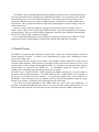
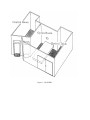
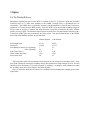
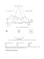
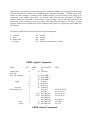
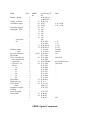
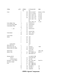
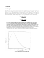
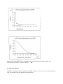
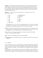
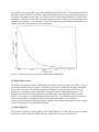
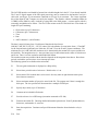
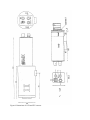
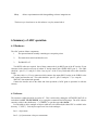
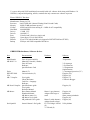
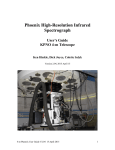
GHRIL User Notes
M.N. Devaney
14 August 1991
ING LA PALMA TECHNICAL NOTE NO. 81
Contents
1
Introduction
2
General Layout
3
Optics
3.1 The Nasmyth Focus.........
3.2 GHRIL Optical Components
4 Detectors
4.1 The IPD
4.1.1 Description
4.1.2 The User Interface .
4.1.3
Operation
4.1.4 The Peltier Cooler .
4.1.5 Recording data
4.2 TV cameras
5 The Video Control Box
5.1 Operation...........
5.2 Software . . . . . . .
6
Summary of ADC operation
6.1 Hardware
.........
6.2 Software
..........
7 The GHRIL PCs
8 The Exabyte
9 Cables
10 Telescope Commands
11 Acknowledgements
1
Introduction
The GHRIL is the Ground-Based High-Resolution Imaging Laboratory on the 4.2m William Herschel
Telescope in the Observatorio del Roque de los Muchachos, La Palma. It is an enclosure with an optical
bench allowing access to one of the WHT Nasmyth foci. This arrangement allows experiments to be
carried out without the necessity to engineer support structures -experiments are simply mounted on the
optical bench. This is of particular benefit to experiments in high angular resolution imaging, but is also
useful to other areas.
There are a range of optical components, detectors and computing, facilities available to users of
GHRIL. Here, a more or less complete list of GHRIL hardware is provided. although such a list requires
constant updating. The use of various GHRIL components is described, but it should be understood that
none of these items are fully- supported by the RGO.
It is recommended that potential users of GHRIL also consult. the La Palma User's Guide' for further
information necessary for the planning, of observations with the William Herschel Telescope.
2 General Layout
The GHRIL is all enclosed optical laboratory, situated on the ´´cable-wrap´´ Nasmyth platform of the 4.2m
William Herschel Telescope. It consists of two compartments: the optics room, containing the optical
bench. and a control room.
Besides the optical bench, the optics room contains a large number of optical components. These are listed
elsewhere in this document. Three detectors are currently available two television cameras (a CCD TV and
an Intensified TV) and a Imaging Photon Detector (IPD). It is possible to store data from these detectors
using hardware &, software on the GHRIL PCs. An Atmospheric Dispersion Corrector (ADC) is
available, and is controlled using menu-driven software on its own PC.
The WHT may be controlled from the VT220 terminal in the GHRIL control room. It is also possible to
display the telescope information there. Two 8MHz IBM PCs and a 25 MHz Elonex AT are available to
the user as well as RGB and Video monitors. It is possible to transfer data. to the VAX8300 via
ETHERNET. Video data may be processed with the aid of two FG100 frame grabbers, and stored using a
betamax video recorder. Hardcopies may be obtained using the video-printer.
Fig.1 shows the general appearance of the GHRIL while fig. 2 gives some useful dimensions. In
particular, it should be noted that the optical axis is 15 cm above the table, and the Nasmyth focus is 15 cm
from the front end of the table and 30 cm from the side of the table nearest the GHRIL control room.
Figure 1. The GHRIL
Figure 2: The GHRIL enclosure and optical table - side and plan elevations. All dimensions are in mm.
3 Optics
3.1 The Nasmyth Focus
Information regarding the optics of the WHT is available in the I-X, G Observer's guide and La Palma
Technical Note no. 9. Some data pertinent to the GHRIL Nasmyth focus is reproduced here for
convenience. The GHRIL focus is selected by insertion of the Nasmyth fiat; a 616x432 mm Cervit mirror,
positioned at 1750 mm from the WHT primary. Since the WHT uses an alt.-azimuth mounting, images at
all foci rotate as an object is tracked. An image derotator is provided to counteract this effect, with the
penalty of a loss of light. The derotator employs prisms of fused silica. with total internal reflection, with a
1.5mm thick UBKI7 glass lens cemented to one of the prisms. The optical characteristics of the GHRIL
focus with and without the derotator are presented here.
Focal length (mm)
Focal ratio
Field diameter (arcmin) (no vignetting)
(50% vignetting)
Scale (arcsec mm-1)
Diam. central obstr.(mm)
Focus/mirror shift
without derotator
with derotator
45738
f/10.94
7
23
4.51
1210
20
46419
f/11.11
2.5
5
4.44
1210
21
The Focus/mirror shift is the movement of focus position for unit movement of secondary mirror. If the
focal point is shifted by moving the secondary mirror, the best theoretical image enlarges by 0.18" for each
100mm of focus movement (i.e. for each 5mm shift of secondary). A change in focal length occurs when
the secondary mirror is moved as shown in the following table.
Users are advised to install the de-rotator (if it is needed) before assembling their imaging, optics on the
optical table.
Figure 3: The Nasmyth image derotator
Figure 4: Images produced if the f/11 focus is moved outwards by 50, 100 and 150 mm
Movement of focus (mm)
Movement of sec. mirror
Focal length
50
2.46
46362
4.92
46524
100
46687
150
7.38
A diagram of the image rotator optics, and the spot diagrams as the focus is moved are reproduced here. Other
useful spot diagrams are available in La Palma technical note No. 9.
3.2 GHRIL Optical Components
There follows a list of the optical components presently- available at GHRIL. The Catalogue references should
allow the interested user to find more information on the individual components. A GHRIL optics guide
(written by Isabel Escudero), available from the GHRIL manager gives useful advise on the setting up of
components on the GHRIL optical table. An artificial source currently under construction will greatly
facilitate alignment of components: it will comprise a laser providing a beam at the same height above the
optical table as the telescope axis (1,50 mm). and a white light source providing, all f/11 beam. A small
telescope mounted on the GHRIL bench allows definition of the optical axis using targets on the GHRIL and
UES rotators.
The following abbreviations are used in the table of optical components:
A
E
M
N
Aerotech
Ealin
Melles Griot
Newport
ord
mis
brk
IAC
ordered
missing
broken
Instituto de Astrofisica de Canarias
GHRIL Optical Components
ITEM
QTY
Adapter plate
Allen keys
Base., adj. mounting
..sliding
...universal
Beamsplitter. plate
...,cube
..,pellicle
10
2
2
2
12
12
16
4
1
1
1
1
2
1
2
1
GHRIL
No.
CATALOGUE
No.
25 N M-Bl-A
28
29
30
31
32
35
26
13-02
13-02
15
18
N M-AMB-1
N M-AMB-2
N M-AMB-3
N M-B-2
N M-B-2A
N M-B-1A
N M-BU-P
E 24-5043
E 36-884
M 03 BTF 021
M 03 BTF 021
M 03 BTF 023
M 07 RMS 001
M 03 BSC 007
M 03 BPL 001
DIM.
40X55X5.50x50
dia=63, 50/50
dia=50, 30/70
dia=50, 50/50
dia=50, 50/5
20x20x20
dia=25.4
GHRIL Optical Components
ITEM
QTY
Bracket., 90 degr.
Clamps., tie down
Collimator/Camera
Collimator supports
Diaphragm, fixed
spare plates
iris
Diffuser, ground
... , opal
Eye piece, Ramsden
Fibre holder
Filter, color glass set
....color glass RG610
.....interference
.....ND set 0.1-1.0
.....ND 2.0
......... 3.0
...........4.0
...........1.5
...........2.0
...........3.0
...........4.0
Filter holder
Height adj. ring
Laser, He-Ne
... ,diode
Lamphouse+diaphr+
T/Hlamp
Lamp. Tung/Hal
Laser mount
GHRIL
No.
2
1
8
1
1
2
1
1
1
1
1
1
1
1
1
1
1
2
1
1
1
1
2
1
1
1
2
2
2
2
3
6
2
1
1
3
1
1
1
37
86
86
85
74
75
76
77
79
71
72
02/03
04
19
04
70
47
22
CATALOGUE
No.
N M-360-90
A HDZ-3M
N M-CL-6
ICOS
ICOS
IAC
IAC
IAC
IAC
IAC
IAC
IAC
E 22-3859
E 22-3859
N M-ID-1.0
N M-ID-1.5
E 26-6502
E 26-6528
E 24-9821
E-35-7426
E 26-3004
E 26-4390
M 03 FIR 006
E 35-7624
E 26-5876
E 26-5884
E 36-5892
E 35-5917
E 35-5933
E 35-5958
E 35-5974
N M-FH-2
N C-1
N U-1301
LDM 135
E 28-7532
E 28-7532
57 N M-812
58 N M-807
N M-811
DIM.
F/15, f=600
F/11, f=440
1-16
1-16
1.5-28
2.5-41
50x50x2
50x50x3
15x
50.8x50.8
´´
dia=25/20,656.0 nm
50.8X50.8
´´
´´
´´
´´
´´
´´
´´
44.7
GHRIL Optical Components
ITEM
QTY
Lens
Lens adaptor ring
Lens focussing mount
Lens holder, fixed
...., var.
Lens mount
Lens tissues
Mask
...,spare plates
Micropositioner
Microscope obj. set
Microscope obj. holder
Micrometer
Mirror, flat
Mount, gimbal
...., mirror
...., mirror adaptor
Polarizers. dichr. sheet
Polarizer mount
Post
GHRIL
No.
1
1
1
1
1
1
1
1
4
2
9
10
4
1
2
10
10
08
09
86
87
88
1
1
1
1
1
80
81
82
83
84
1
2
2
2
1
4
2
1
1
2
2
2
2
4
4
20
30
6
CATALOGUE
No.
M 01 LAU 067
M 01 LAU 089
M 01 LAO 138
M 01 LAO 248
M 01 LAO 256
M 01 LAO 138
M
M 01 LPX 159
N LPTH-1T
N M-LFM-1
N LH2-T
N LH1-T
N M-VLH-3
DIM.
dia=50, f=550
50, 750
40, 120
40, 300
50, 300
40, 120
100
35, 85
67
62
63
64
65
65
66 N M-LVM-1
59 N M - LM- 2
60 N M-LM-1
10
11
IAC
IAC
IAC
IAC
IAC
IAC
E
N M-set
N M-FH-2
N LH1-M
Mercer 43
M 02 MFG 021
M02 MFG 017
53
54
12
55
16
17
44
45
46
A AOM110-3M
N M-600A-4R
N A-4-3
M 03 FPG 007
N M-RSA
M 07 RMS 001
M 07 RMS 002
N M-SP-2
N M SP-3
N MSP-4
73
68
69
5-60x
.0001 inch
dia=75
dia=45.4
50
76
101
GHRIL Optical Components
ITEM
Post clamp
.... collar
.... holder
Prec. screwdriver set
Prism table
Rail
Retard. plate
Rod
... , damped
Rod clamp
Scissors Jack
Screw set
Stage, rotation
...., translation
Target
Window
QTY
GHRIL
No.
20
10
10
16
10
4
2
2
2
6
1
1
1
1
1
1
1
1
2
2
4
2
2
2
6
2
2
1
38
39
48
49
50
51
52
CATALOGUE
No.
N M-CA-1
N M-CA-2
N M-MPC
N M-VPH-2
N M-VPH-3
N M-VPH-4
N M-VPT-4
N M-VPT-3
56 N M-T-1
20 N M-URL-18
N M-URL-36
06 M 02 WRM 009
76 M 02 WRM 029
41 N M-340
40 N M-375
42 N M-375-C
43 N M-340-C
23
24
36
34
27
33
N M-SK-M6
N M-SK-M4
N M-BS-1
N M-RSK-1
N M-TSX-1B
N M-TSX-1A
N M-431-1
A ATS30-3M
DIM.
l=457
l=917
dia=50, 1/4
dia=50, 1/2
25
dia=106
4 Detectors
An Imaging Photon Detector (IPD) and two TV cameras, one of which is intensified, are available at
GHRIL. The GHRIL user may also use RGO CCD chips which are normally in use at other focal stations
- details of these chips are available in La Palma Technical Note No. 55. They may be mounted on the
GHRIL table (an L flange is available), and controlled from the ICL console in the WHT control room, and
the data. stored on a VAX 8300. Any user wishing, to use an RGO CCD should contact the GHRIL
manager well in advance of the observing, run in order to ensure availability.
The GHRIL TVs and IPD may be controlled and data from them stored using the GHRIL PCs.
4.1 The IPD
4.1.1
Description
The IPD consists of a photocathode, micro-channel plate amplification stage and a resistive anode. The
MCP is used in saturated gain mode, resulting, in a peaked pulse height distribution. This allows
adjustment of lower and upper thresholds to discriminate photon events. The charge cloud from the final
MCP stage impinges on a square uniformly resistive anode sheet. The four corners of the sheet are
connected to amplifiers., and the resulting charges, A, B, C, D., give the photon X and Y coordinates by;
X = A+B - (C+D)
A+B+C+D
Y = A+D - (C+B)
A+B+C+D
Fig. 5 shows the measured RQE of the S20 photocathode of the GHRIL IPD. The peak value is
23.5% at 451.4 nm. The detected quantum efficiency (DQE) is given by the photocathode RQE
multiplied by the efficiency of coupling primary photoelectrons into the MCP and the efficiency of the
anode pulse detection and signal processing system. Assuming (optimistically) an efficiency of 70%
for the transfer of photoelectrons to the MCP and an electronic detection efficiency, of 90% leads to a
peak DQE of 15%. However, measurements on standard stars indicate that the DQE is
~ 2% in the B band (380 - 500 nm). The device has not been calibrated in a photometric laboratory.
Figure 5: Measured RQE of the GHRIL IPD
The maximum count rate is of the order 200000 counts per second, corresponding to a global dead time of
about 5 microseconds, mainly due to the limited speed of the electronics. There is a much more serious
local dead time problem; the individual micro-channels have dead times of order tens of milliseconds. This
may lead to a hole in the middle of the images of small bright objects.
Fig. 6 shows the measured point spread function and corresponding modulation transfer function for the
GHRIL IPD. The cathode diameter is 25 mm and 8 bit pixels were employed (pixel size is 97 micron).
The IPD PSF and MTF may well not be the same as when these measurements were made: they will have
changed if, for example, the internal gain settings are altered.
While the FWHM in this experiment is seen to be less than one pixel, there is a halo of intensity which
extends a large distance from the peak.
The IPD flat-field may show a tartan pattern, probably due to non-linearity of Analogue-to-Digital
converters in the processing electronics, and a reduction of sensitivity from the centre of the image.
Figure 6: PSF of the GHRIL IPD as measured by the group from Imperial College London, and
MTF obtained by fitting a. gaussian to the PSF.
4.1.2 The User Interface
The IPD is connected to the User Interface via 4 BNC cables (A, B, C, D,) , and a. 6-way Lemo power
lead. The outputs of the User Interface are described here;
Analogue X-Y : 2 BNC sockets for real time display of image. The X and Y coordinates of each detected
photon are output as voltage levels from 0 to 10 volts. The values for each event are held until the next
event is computed. An oscilloscope connected in X-Y mode will therefore display the image as a series of
dots. The persistence of the screen together with that of the eye will enable an image to be seen. Note that
the analogue output will not drive cables as far as the WHT control room; if this is required then the user
must provide suitable line drivers.
Digital X-Y : 2 15 way D-15P connectors carrying, digital X-Y coordinates plus strobe. The pin
connections are as follows ;
1
2
3
4
5
6
7
8
bit 8
bit 7
bit 6
bit 5
bit 4
bit 3
bit 2
bit 1 (MSB)
9
10
11
12
13
14
15
Output data strobe
Data inhibit
bit 11
bit 12
ground
bit 9
bit 10
The standard output is 10 bits. Pin X9 is connected internally to pin Y9 and pin X10 is internally
connected to pin Y10. All logic is TTL level. The output data, strobe is a 1 microsec negative going
pulse, and data is valid until the next output data. strobe (i.e. at least 6 microseconds).
Rate 1 & 2 : 2 BNC sockets, outputs from frequency to voltage converters. Rate 1 measures the rate of
incoming photon pulses as detected by the lower threshold comparator while rate 2 measures the rate of
processed photons. The scale for both outputs is 1 volt = 10 000 counts per second.
Strobe : BNC socket. The output data strobe which is also present on pin 9 of the digital
outputs. It is useful for photon counting
Pulse : This is the summed charge from the four charge amplifiers.
Tecmar Connector : 40 way ribbon connector on rear panel, for connection to Tecmar board in
GHRIL PC.
4.1.3
Operation
Connect the four BNC leads (A, B, C, D) and the lemo power lead between the IPD housing. and the signal
processor. The image may be monitored by connecting the X & Y analogue outputs to an oscilloscope inXY mode. (timebase set to X-Y, mode to ALT, set VOLTS/DIV to 5 and use horizontal and vertical position
controls to find image of cathode). A counter should be used to monitor the count rate (connect to
STROBE).
Before switching on the IPD, ENSURE THAT THE PHOTOCATHODE IS NOT EXPOSED TO
ILLUMINATION. If light is visible to the dark-adapted eye. it is too bright for the IPD. Do not rely on
the EHT trip to save the device, as the trip is driven by the pulse counter, and the IPD will not produce
pulses when severely overloaded. Turn on the mains power on the front panel. The red LED on the left of
the panel is the EHT indicator. The EHT is always off on mains power up, and is turned on by pushing, up
the toggle switch under the EHT light. The LED will come on and an image should now be visible on the
oscilloscope. The EHT is turned off by pushing the toggle switch down. In the absence of illumination, the
total dark count should be < 100 counts per second. If it is significantly higher then the IPD should be left
running, in the dark, with the cooler on for several hours.
Figure 7: Calibration chart for the thermistor attached to the GHRIL IPD
4.1.4 The Peltier Cooler
The Peltier cooler unit will reduce the IPD temperature to about 25 deg. centigrade below ambient. This is
useful when low dark counts are required. The Peltier power unit is a constant current supply, and should
be set to about six amps. The optimum current may be found by experiment; a value which is too low
provides less cooling power while a value which is too high produces a noticeable heating effect. The
temperature may be monitored by connecting a digital Ohm meter to the single BNC connector on the
housing. This connects to a calibrated thermistor on the IPD body. The calibration chart is presented here.
The cooled housing has a sealed glass window in front of the photocathode. If it is considered
necessary to operate the IPD without the nitrogen in then a constant purge of dry nitrogen must be arranged
to prevent condensation on the photocathode window.
4.1.5 Recording data
There is a data acquisition system available on the GHRIL IBM PCs. It is described in detail in a manual
which, may be obtained from the GHRIL manager. A quick aside to its use is provided here.
The IAC IPD interface card should be Inserted into a double-length slot in the PC. if not already installed.
The X and Y digital outputs of the IPD signal processing, unit are connected to the Interface card via a
cable with two D-type 15 pin connectors connected to a D type 25 pin connector. The 8 most significant
bits of the digital X and Y outputs are read by the interface. The interface software currently resides in
C:GHRIL on the IBM Pcs, and is invoked by typing IPD at the DOS prompt. A menu appears which is
reasonably straightforward to follow. The files of data written to the PC hard disk have a text header of
length 512 bytes containing:
•
•
•
•
•
Object name (up to 25 characters)
Comments (up to 70 characters)
Time
Date
ASCN character 1 (end of header)
The data is stored in binary form. Each frame of data has the byte format
(NN,00,LT,MT,XX,YY,XX,YY,...,XX,YY) where NN is the number of events in the frame, LT and MT
are the least and most significant bytes of the time, XX and YY are the X and Y photon coordinates. The
minimum file size is 64K, while the maximum size is determined by the amount of free space available on
the hard disk. The integration time (i.e. time per frame) may be chosen between the values of 100 microsec
and 50 ms. There is no time resolution within individual frames.
The maximum count rate possible with the interface depends on the integration time chosen. Short frame
periods overload the system as there is one interrupt per frame.
The following options are available on the main menu:
F1
The user guide information is displayed as a Help facility
F2
Select frame period in units of microsecs. Default value is 1 ms.
F3
Select name of file in which data is to be stored. One may enter an eight character name plus a
three character extension.
F4
Select maximum number of bytes to be stored in the file. The program test if there is enough free
disk space. The size specified will be truncated to a multiple of 64 Kbytes.
F5
Specify object name, up to 25 characters.
F6
Comment to be included in file header.
F7
Provide real time view of IPD image (in monitor connected to FG-100).
F8
Examine stored data file. Choosing detailed information option shows X and Y photon addresses,
frame time, total number of events etc.
F9
Start data acquisition. Continues until specified amount of data has been obtained or a key is
struck.
F10
Exit
4.2 TV cameras
Two television cameras are available at GHRIL ; a CCD camera. and the same plus intensifier. Fig.8 gives
the dimensions of these cameras; for details of the rear connections. see the "MX CCD High-Resolution
Camera' manual. The cameras may be gen-locked to all external video signal., with 11.25 MHz being the
best sampling frequency. Alternatively, in the 'pixel synchronous' mode', when a 22.5 MHz. clock signal is
connected to the camera, it will switch off the internal crystal clock. The pixels are shifted out of the
camera every second rising edge of the clock signal.
The Intensified TV utilises a two stage image intensifier tube - the first stage is a proximity focused MCP
wafer while the second stage is an electrostatically focused demagnifying Gen.I tube. An S25 photocathode
having, a spectral range of 400-900 nm is used. Some features of the TV cameras are summarised here
(the source of the data is the TV manual, the camera parameters have not been tested):
Intensifier Section
Useful Input area
Input window
Photocathode sensitivity at 800 nm
Resolution
Magnification
min 17.5 mm diagonally
Filter optic
~ 3.5 % RQE
~ 20 lp/mm front face, 10 % modulation
0.37
Image Sensor
Number of pixels
Pixel size
TV standard
Video signal
Supply Voltage
604(H) * 575(V)
10 * 15.6 micron
CCIR 625 lines interlaced or EIA 525 lines
1 Vpp in 75 Ohm
12V, 190 mA
Figure 8: Dimensions of CCD and ITV cameras.
5 The Video Control Box
The GHRIL Video Control Box (VCB) is designed to allow easy and flexible use of the video detectors
(ITV and CCD TV) at GHRIL. It may be used to connect the detectors to monitors. Video Cassette
Recorders (VCRs) and the FG100 frame grabber on the IBM AT. It includes power supplies and controls
for up to three cameras. The VCB contains the following features:
• A power supply for the internal hardware and up to three detectors.
• Three detector controllers, with power on/off switch. frill gain control and connectors for video outputs
and external synchronisation. Each controller has an intensifier (INT) gain and a CCD gain. The gain is
minimal when the detector is switched on, setting becomes active only when it is first turned to the
minimal position.
• A single LCD Voltmeter to measure gain-settings and temperatures. Two switches select the desired
detector (1,2 or 3) and the desired function (INT gain, CCD gain or Temperature) to be displayed.
• An FG100 Interface Panel (at the rear of the box).
• A Video Distribution Unit to ease changing of video connections. It has eight video inputs and eight
video outputs; any of the outputs may be connected to any of the inputs.
5.1 Operation
A typical required set-up would include both video detectors connected to the VCB, with outputs to an
RGB monitor, VCR and the FG100. Such a set-up will be described here.
The FG100 should be connected to the FG100 panel at the back of the VCB by the FG100 cable (grey,
ribbon cable with 10 BNCs at one end). Connecting the BNCs to the appropriate connectors on the panel
(they are labelled. One output of the distribution unit should be connected to input 0. which is the rightmost connector on the bottom row of the FG100 panel.
The RGB monitor should be connected to the FG100 panel by three BNCs: Red, Green, Blue & Sync.
These should be connected to the rightmost four connectors on the top row of the FG100 panel.
The detectors may be connected directly to the D25 plugs on the back panel of the VCB. The three
BNC connectors next to each of the plugs are outputs for Video, with and without synchronisation, and an
input for external synchronisation. You may connect one or both outputs to an input of the distribution
unit. The VCR may be connected to an output of the distribution unit.
Using the thumbwheel switches on the distribution unit, any output may be connected to any input.
Also, one input may be connected to several outputs at the same time. For example, to connect output C to
input 6, the buttons on the thumbwheel marked C should be punched until the number 6 appears.
When first switched on, the CCD and intensifier gains are minimal. To change them, it is necessary. to
turn the appropriate switch or potmeter fully, counter-clockwise - a green LED will come on. Gain setting
can be read from the panel meter. It is controlled by two switches, one to select the detector (1. 2, or 3), the
other to select the function CCD gain (CCD), intensifier gain (INT) or Temperature (C)). It is useful to
check the output of the detector by observing its output with the RGB monitor. It is now possible to
attempt grabbing frames with the FG100.
5.2 Software
In the directory C:GHRIL on the GHRIL PCs, there is a suite of software based on the FG100 frame
grabber. This is invoked by typing TV at the DOS prompt, and presents the user with a menu of options.
The menus are straightforward to follow and will only be described in general here. A preliminary version
of the "ITV Cookbook' provides details, but is not yet reliable.The list of options presented on entering
themenu are presented here. Choosing an option results in several sub-options being presented and these
may involve even more options. It is possible to move back up a level by pressing ESC.
Help
Not implemented
Set up
Allows calibration of the FG100 and Camera. The focusing aid and image scale
determination options are not implemented.
Obs.
Allows recording of data on VCR along with information screens.
Transfer Transfer of data to/from video tape.
Misc
Includes ImagePro and FG100 Toolbox routines. The manuals for these packages are
available (do not seem to work..).
Sharp
Allows image sharpening to be carried out in real time. This uses a bright reference star to
remove image motion and to select frames passing a certain quality criterion. The suboptions are as follows;
Log
Information to be stored (object name etc.)
Wind
Define a window around the reference object
Select
I
Sharp
Define frame selection parameters (flux,width)
Result
Plot profiles and greyscale images of sharpened and passively recorded images, giving
values for FWHM
Trck
Plot time-tracks of image position, flux and width
Store
Store the result
Seemon
Estimate the seeing by measuring the differential motion of images formed by separate parts
of the telescope aperture. Two windows need to be defined before the monitoring is carried
out
IPD
Runs the IPD interface menu (see section on IPD)
Perform the image sharpening run
PLay
Allows experimentation with framegrabbing, real-time integration etc.
The best way to learn how to use this software is to play around with it.
6 Summary of ADC operation
6.1 Hardware
The ADC consists of three components:
1.
The opto-mechanical assembly containing two composite prisms
2.
The stand-alone control and interface unit
3.
The IBM PC-AT
Two RS232 cables are required. One of these connects the 9 pin RS232 port of the PC into the 25 port
connector in the control room (rear of cabinet 'U' beside control desk. GHRIL RS232 port 3). This cable
should be : pins 2-2, 3-3 and pin 5 of the 9 way to pin 7 of the 25 way. Both ends of this cable should be
female.
The other cable is a 25 way connector which connects the output RS232 socket in the GHRIL to the
ADC control and interface unit. This cable should be : pins 2-3, pins 3-2 and pins 7-7 (i.e. swap the
XMT RCV but maintain the ground).
Connect the interface unit to the mains and check operation (cf ADC guide to operation in reference
section).
6.2 Software
The timezone variable should be set on the PC. This is achieved by editing the AUTOEXEC.BAT file to
include the line SET TZ=WET0WDT or by typing this command at the DOS prompt. The ADC software
currently resides in the subdirectory ``C:\CHRISD’’; to get there type cd c:\chrisd.
It is advisable to edit a catalogue of objects which are to be observed (the editor EDT is available in the
directory ``C:\EDT’’). Each object requires two lines in the catalogue:
line 1 = object name
line 2 = [+/-]nn:nn:nn.nn whitespace nn:nn:nn.nn
where the first number is the object RA and the second number is the object DEC. Type d to run the
ADC program; enter the current date and UT at the prompts. A typical sequence of commands is the
following:
cat
enter catalogue mode
read
input a catalogue (program will prompt for catalogue name)
add
add a a new object to the catalog
next
input object from catalogue
move start observing the object
go
update prism positions - only used after first object has been selected
Additional useful commands include:
force force prism positions to be updated
help
provide list of available commands
setup enable default temperature, pressure etc. to be changed
quit
finish
Detailed descriptions are provided in the ADC manual in the reference section.
7 The GHRIL PCs
There are three PCs available to the GHRIL user: two 8 MHz IBM PC-ATs and a 25 MHZ Elonex AT.
The IBM PCs are intended to be compatible at all times (e.g., new cards are supplied in duplicate). On the
following two paces is a table of the Hardware, Software and Documentation available for these two PCs.
In the table, (L) and (S) mean long and short cards respectively.
The Elonex PC should provide users with a higher performance but compatible AT environment. It has
been tested with DOS, SCO UNIX and ISC UNIX.
It is suggested that a small DOS partition be left at the beginning of the hard disk while the remainder may
be used in the following ways as required:
1.
an extended DOS partition for scratch data storage.
2.
UNIX filesystems, swap areas. etc.
This arrangement means that users cannot expect that their data or preferred disk structure will survive
between GHRIL runs and should take appropriate backups. The permanent primary DOS partition is of
3.3 type (to help with UNIX installation) but actually holds 4.01 software which along with Windows 3.0.
GW-basic, setup and disk-parking, utilities, constitute the only common user software at present.
Elonex GHRIL PC Hardware
Manufacturer
Processor
Memory
I/O Bus
Hard Disk
Drive A
Drive B
Ports
Display
Ethernet
Backup
Elonex plc, UK.
Intel 25 MHz 486. (Internal Floating Point Unit and Cache)
8 MB (32 MB maximum capacity)
4 EISA and 4 ISA slots running at ~ 8 MHz for AT compatibllity
640 MB ESDI
1.2 MB 5.25"
1.44 MB 3.5"
2 Parallel and 2 Serial on a single card
Genoa Super VGA (1024x768x16)
3Com 3C503 (thick and thin wire support for DECNET-DOS and TCP/IP)
EXAbyte with VMS-compatible DOS driver
GHRIL IBMs hardware, Software & docs.
Item
Documentation
IBM Manuals
MS DOS 3.30
Guia de Operacion(1&2)
Manual de Consulta (1 binder)
Guia del Usario
Reference
Quick Reference Card
Xenix
DECNET-DOS
V2.0
MS C Compiler
MS Pascal Compiler
MS-Mouse
Serial/parallel
Hardware
"Explorando
3.30 Arranque
3.30 OPeracion
3.2 Programmas
Suplementarios
3.3 Arranque/Operacion (3.5")
Floppies (22*)
Floppies (9*)
Floppies (7*)
Codeview debugger
Manual (7*)
Various manuals (2*)
User's guide
Library Reference
Codeview + Language
Reference
Quick Reference guide
User's guide
Reference Manual
Show Partner Manual
Paintbrush Manual
MS Mouse menus (3*)
MS Mouse User's guide
MS paintbrush User's guide
Owner's Manual + Ref. guide
Software
Floppies (2*)
Mouse 1 (grey buttons)
Adapter cable large to
small
Mouse 2 (white buttons)
Adapter (small to large)
EV-170A Magic I/Ocard
(S)
??? I/Ocard (S)
Floppies (6*)
Installation
Show partner/paintbrush
Floppies (4*)
Floppies (4*)
Utility diskette
Memory Extensions
Manual (3*)
Same Manual ?
Above Board plus Manual
Ethernet
Installation sheet
Owner’s manual (1*)
Installation Guide
Installation Guide
FG100-AT
FG100 AT User's Manual
ITEX Library
ImagePro
Texmar Interface
ITEX 100 Programmer's
Manual
Manual
IPD guide (small)
IPD guide (large)
Installation Manual + User
Guide
MATH Coprocessor
Mountain filesafe
Installation instructions
User guide
Installation guide (3*)
IAC IPD Controller
Extender
Spurious I/Ocard (S)
Parity W5-300
card(128k)(L)
Parity W5-500
card(1Mb)(L) INTEL
Above BoardPlus(L)
Micom Interlan board (S)
AMP Transceiver
DEPCA Network Card
(L)
DEC Mouse
DEC Keyboard (4*)
3COM501 (1) (S)
3COM501 (2) (S)
FG- 100-AT (1) (L)
coax Flatcable
FG-100-AT (2) (L)
coax Flatcable
Instal. floppy
?
Installation + test
Installation + test
Hardware diagnostics
Toolbox 100
hardware Diagnostics
Toolbox 100
Itex 100 Library
floppes (5*)
IPD board rev. 3.3 (1)
(L)
IPD software
IPD board rev. 3.3 (2)
(L)
Sc. Sol. base board (s)
80287-8 Chip
Tape unit
(connected as floppy b:)
Extender card (L+L on
top)
Flat cable
Extender board (4*S)
HAL release 870309
Instal. test
Floppies (4*) (3*)
8 The Exabyte
An Exabyte tape drive is available for storing data from the PC hard disks. A set of commands is available
to allow files to be written to and from the Exabyte tape drive. All the commands can operate on both the
PCs running DOS and a VAX running VMS, allowing the Exabyte to be used to transfer data between the
two types of machine. The \Dev=device switch must be present for all VAX commands. If the specified
device is not mounted, then the utility will attempt to mount the device.
The following is a summary of the commands available. Square brackets specify an optional switch.
XINIT
Initialize the contents of a tape to allow the other EXABYTE commands to recognize it. After
initialization, data that was previously on the tape is no longer accessible. Each tape is given a unique label
derived from the current time and date (hhmmssdd.mm$).
XDIR file_spec [/Over]
Display a list of the files stored on the tape. The /Over switch forces the utility to locate the directory
information on the tape, rather than searching for the directory, file in the Home directory. file_spec can
include the wildcard operators * and ?. If file_spec is proceeded by @, then file_spec is assumed to be a
text file of file specifications.
XREAD file_spec destination [/Over]
Read file(s) from tape, recreating the file(s) on disk. The file is created in the current directory if
destination is not specified. The file_spec can contain wildcard operators. If the file already exists on disk.
the user is prompted to confirm overwriting with the tape version.
XWRITE file-spec
Write file(s) to tape. If the file being written already exists on tape then the directory entry is modified to
indicate that the file has been superseded. The /Dir and /Read commands both ignore files that have been
marked as superseded.
XRECON
Reconstruct the directory information for a tape that has either not had directory information written to it or
that has suffered an error (e.g. due to power failure or a user-aborted write command). The utility creates
an empty directory file with the same name as the tape label in the Utilities home directory. The contents of
each file on tape are read and if the number of blocks used to store a file agrees with the file size indicator,
then a directory entry is created. When all files on tape have been checked, the contents of the new directory
file are written to tape.
Information on the organization of data on tape, and the Installation of the utilities is available in the User
Specification document.