1
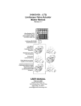
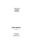
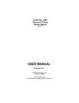
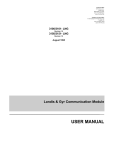
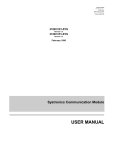
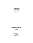
3100/3150 - YRK
York Chiller
Master Module
Revision 1.0
USER MANUAL
April, 1997
ProSoft Technology, Inc.
9801 Camino Media
Suite 105
Bakersfield, CA 93311
[email protected]
Please Read This Notice
Successful application of the YRK card requires a reasonable working
knowledge of the Allen-Bradley PLC or SLC hardware and the application in
which the combination is to be used. For this reason, it is important that those
responsible for implementing the YRK satisfy themselves that the combination
will meet the needs of the application without exposing personnel or equipment
to unsafe or inappropriate working conditions.
This manual is provided to assist the user. Every attempt has been made to
assure that the information provided is accurate and a true reflection of the
product's installation requirements. In order to assure a complete
understanding of the operation of the product, the user should read all
applicable Allen-Bradley documentation on the operation of the A-B hardware.
Under no conditions will ProSoft Technology, Inc. be responsible or liable for
indirect or consequential damages resulting from the use or application of the
YRK product.
Reproduction of the contents of this manual, in whole or in part, without written
permission from ProSoft Technology, Inc. is prohibited.
Information in this manual is subject to change without notice and does not
represent a commitment on the part of ProSoft Technology, Inc. Improvements
and/or changes in this manual or the product may be made at any time. These
changes will be made periodically to correct technical inaccuracies or
typographical errors.
Copyright 1997, ProSoft Technology Inc.
Product Revision History
04/9/97
Revision 1.0
Initial release of product
Implementation Guide
Integration of the YRK module into a PLC or SLC application is easier the first time if a series of steps are
followed. In order to assist the first time users of our products in getting the YRK operational quickly, we
have come up with this step-by-step implementation guide.
a)
Starting with one of the ladder logic programs provided on disk with the YRK complete the following
steps:
PLC 5
YRK5
SLC 5/03
YRK503
b)
Edit the ladder logic provided on disk as needed for the application
Verify rack and slot location in program
Modify ladder instruction addresses as needed
Reference Appendix for tips in the SLC platform
c)
Setup the Communication Configuration parameters (See Section 2)
Determine the configuration requirements:
Baud Rate, Number of slaves, page map requirements, etc.
d)
Identify the jumper requirements (See Appendix)
e)
Make up the communication cables (See Section 5)
f)
Place processor into the run mode
g)
Monitor the data table Error Status values (See Section 2)
ii
Table of Contents
Revision History
Implementation Guide
i
i
1 Product Specifications ............................................................................................................................1
2 YRK Theoretical Operation .....................................................................................................................1
2.1 Block Transferring Data to the Module .............................................................................................2
2.1.1 Communications Configuration [ BTW Block ID 255 ] ................................................................2
2.1.2 Write Page Data Command Blocks [ BTW Block ID Code 0 to 5 ]..............................................4
2.1.3 Page Polling List [ BTW Block ID Code 80 and 81 ] ...................................................................7
2.2 Transferring data from the module [ BTR Block ID 0 to 59 ]..............................................................9
2.2.1 The Read Data Block Structure .................................................................................................9
2.2.2 Moving the data from the module to the processor.....................................................................9
2.2.3 Slave Data Results..................................................................................................................10
2.2.4 Command Done Bits ...............................................................................................................12
2.2.5 Module Information Table........................................................................................................13
3 Protocol Commands.............................................................................................................................13
4 Diagnostics and Troubleshooting ..........................................................................................................14
4.1 3100 PLC Platform LED Indicators.................................................................................................14
4.2 3150 SLC Platform LED Indicators.................................................................................................15
4.3 Troubleshooting - General..............................................................................................................16
4.4 Communication Error Codes..........................................................................................................17
5 Cable Connection .................................................................................................................................17
Appendix
Support, Service and Warranty
Jumper Configurations
SLC Programming Considerations
Example Ladder Logic
PLC-5
SLC-5/03
1
Product Specifications
The 3100/3150-YRK (“York Master Module”) product family allows Allen-Bradley 1771 and 1746
I/O compatible processors to easily interface as a host with up to 15 York Chillers per port.
The YRK product includes the following standard features:
General Specifications
• Support for up to 14 York chillers per port
• RS-232 or RS-485 communications (jumper selectable)
• Software configuration (From processor ladder logic)
Baud Rate
:
1,200 TO 38,400
Message Response Timeout
Number of active slaves : 1 to 15 per port
Prioritized Page Polling List : Up to 90 entries
Active Slave Table
• Response time
The protocol drivers are written in Assembly and in a compiled higher level language.
As such, the interrupt capabilities of the hardware are fully utilized to minimize delays,
and to optimize the product's performance
Hardware Specifications
Backplane Current Load :
3100
: 0.65 A
3150
: 0.15 A at 5 V
0.04 A at 24 V
• Operating Temperature : 0 to 60 °C
• Storage Temperature : -40 to 85 °C
• Connections :
3100
: 2 - DB25 Female Connectors
3150
: 2 - DB9 Male Connectors
•
2
YRK Theoretical Operation
Data transfers between the processor and the ProSoft Technology module occur using the Block
Transfer commands, in the case of the PLC, and M0/M1 data transfer commands, in the case of
the SLC. These commands transfer up to 64 physical registers per transfer. The logical data
length changes depending on the data transfer function.
The following discussion details the data structures used to transfer the different types of data
between the ProSoft Technology module and the processor. The term 'Block Transfer' is used
generically in the following discussion to depict the transfer of data blocks between the processor
and the ProSoft Technology module. Although a true Block Transfer function does not exist in the
SLC, we have implemented a pseudo-block transfer command in order to assure data integrity at
the block level. Examples of the PLC and SLC ladder logic are included in Appendix A.
In order for the ProSoft Technology module to function, the PLC must be in the
RUN mode, or in the REM RUN mode. If in any other mode (Fault/PGM), the
block transfers between the PLC and the module will stop, and communications
will halt until block transfers resume.
1
2.1
Block Transferring Data to the Module
Data transfer to the module from the processor is executed through the Block Transfer
Write function. The different types of data which are transferred require slightly different
data block structures, but the basic data structure is:
Word
0
Name
BTW Block ID
1 to 63
Data
Description
A block page identifier code. This code is used by the
ProSoft module to determine what to do with the data
block. Valid codes are:
BTW
Code
Description
0-2
Port 1 Write Enable and Data
3-5
Port 2 Write Enable and Data
80-81
Page Polling List (Prioritized)
255
Module Communication Configuration
The data to be written to the module. The structure of the
data is dependent on the Block ID code. The following
sections provide details on the different structures.
PLC
Memory
BTW
Block ID
Port 1
Port 2
0
Chillers 1-5
Write Data
1
Chillers 6-10
Write Data
2
Chillers 11-14
Write Data
3
Chillers 1-5
Write Data
4
Chillers 6-10
Write Data
5
Chillers 11-14
Write Data
255
Configuration
Data
BTW
Command
Word
0
1
2
3
4
:
:
:
63
BTW Block ID
Although the full physical 64 words of the data buffer may not be used,
the BTW and M0 lengths must be configured for 64 words otherwise
module operation will be unpredictable.
2.1.1
Communications Configuration [ BTW Block ID 255 ]
The ProSoft Technology module communication parameters must be
configured at least once when the card is first powered up, and any time
thereafter when the parameters must be changed.
On power up, the module enters into a logical loop waiting to receive
configuration data from the processor. While waiting, the module sets the
second word of the BTR buffer to 255, telling the processor that the module
must be configured before anything else will be done. The module will
continuously perform block transfers until the communications configuration
parameters block is received. Upon receipt, the module will begin execution of
the command list if present, or begin looking for the command list from the
processor.
2
Transferring the Communications Configuration Parameters
to the module will force a reset of the communication ports
The configuration data block structure which must be transferred from the
processor to the module is as follows:
BTW
Data
Buffer
Word
Description
0
Block ID Header = 255
Configuration Parameters
1
N[ ]:0
Baud Rate
2
N[ ]:1
Response Timeout
3
N[ ]:2
Port 1 - Max Number of Slaves
4
N[ ]:3
Port 2 - Max Number of Slaves
5
N[ ]:4
Read Block Count
6
N[ ]:5
Block Transfer Delay Count
7
N[ ]:6
Last State on Comm Fail
8-10
N[ ]:7-9
Spare
Active Slave Table
11-24
N[ ]:10-24 Port 1 - Slave Addresses(Up to 15 slaves)
25-39
N[ ]:25-39 Port 2 - Slave Addresses(Up to 15 slaves)
Configuration Memory map for Example Application
Baud Rate
Port 1
Slave
Count
Response
Timeout
Port 2
Slave
Count
Read
Block
Count
BT Delay
Count
0
1
2
3
4
5
6
7
8
9
N7:0
5
500
2
0
4
0
0
0
0
0
Configuration Parm
N7:10
1
2
0
0
0
0
0
0
0
0
Port 1 - Active Slave Table
N7:20
0
0
0
0
0
0
0
0
0
0
N7:30
0
0
0
0
0
0
0
0
0
0
Port 2 - Active Slave Table
3
Name
Description
Baud Rate
The baud rate at which the port is to operate. The available
configurations are as follows:
Value
Baud Rate
2
1200 Baud
3
2400 Baud
4
4800 Baud
5
9600 Baud *
6
19200 Baud
7
38400 Baud
* York Field Unit Factory Default Setting
Message Response Timeout
This register represents the message response timeout period in 1 ms
increments. This is the time which a port configured as a Master will
wait before re-transmitting a command if no response is received from
the addressed slave. The value is set depending on the expected
slave response times. The module has been hardcoded with a
minimum value of 20000 (20 seconds) in order to assure that the unit
works when a chiller is down. Therefore a value of 0 may normally be
entered in this register.
This value is used by the module to optimize the number of data blocks
returned to the PLC data table as well as several of the internal logic
routines. The value entered here can range from 1 to 15.
Port 1 - Max Number of Slaves
Port 2 - Max Number of Slaves
Read Data Block Count
This value represents the number of 50 word data blocks which are to
be transferred from the YRK Module to the processor. The blocks
returned from the module start at block 0 and increment from there.
The maximum block count is 80. Two blocks per active slave should
be requested.
As an example, if there are 2 active slaves on port 1, a value of 4
should be requested to return module registers 0 to 199.
If a value of 0 is entered the YRK module uses the Number of
Slaves configuration value to determine the Read Block Count
value.
Block Transfer Delay Counter
This is an empirical value used by the module to balance the amount
of time the module spends block transferring and the amount spent
handling port communications. The value entered is used as a loop
counter in the module, where each time through the loop the count is
incremented. When the count equals the Block Transfer Delay
Counter a Block Transfer sequence is initiated. A value of zero (0) is
suggested unless directed differently by the factory.
Example : In Master Mode applications with the module in a remote
rack, the frequency of command execution can be improved by
entering a value of 75-150.
The value must be determined
empirically.
Port 1 – Active Slave Table
Port 2 - Active Slave Table
2.1.2
These 15 words allow the user to configure the specific slaves
addresses which are active on a network. The intent of this table is to
allow the user to selectively enable slave addresses and therefore not
having to have sequential slave addressing.
Write Page Data Command Blocks [ BTW Block ID Code 0 to 5 ]
A YRK Master port establishes communications and performs various
communications functions based on the data which the user has placed in the
Command Blocks. The Command Blocks are 50 word data blocks containing bit
mapped ‘Enable Bits’ and actual write data. The actual command which is
executed by the module is determined by the user setting the correct ‘Enable Bit’
to a 1.
4
All commands are one-shoted by the module (ie., the module must see a 1 to 0
transition before the command can be re-enabled with a 0 to 1 transition). The
user may use the ‘Cmd Done Bit’ (See next section) to clear the command or
any other means appropriate. This command data, entered into the processor
Data Table, is transferred to the module's memory using Block IDs 0 through 5,
depending on the command to be executed.
The structure of the data for each slave position is broken down as follows:
Important Note
For the 8 available pages that can be written to (Page 1 to 8), the module
is coded to assume the following data types for the pages:
Pages 1 to 4 :
Analog
Pages 5 to 8 :
Discrete
Word
0
Name
Command Enable
Description
This is a bit mapped word which contains the individual
page write command enables. This bit is one-shoted by
the module to assure that the write command is only
written once. This bit can be cleared in ladder logic using
the Done bit returned from the module.
Bit
Description
0
Cmd Enable - Page Number 1
1
Cmd Enable - Page Number 2
2
Cmd Enable - Page Number 3
3
Cmd Enable - Page Number 4
4
Cmd Enable - Page Number 5
5
Cmd Enable - Page Number 6
6
Cmd Enable - Page Number 7
7
Cmd Enable - Page Number 8
1-8
Write Data
These values are the actual data values (x10) to be
written to the slave.
Example:
121 will write a value of 12.1 to the chiller
9
Spare
Not Used
Command
Enable
Word
Spare
Data for Pages 1 - 8
0
1
2
3
4
5
6
7
8
9
8
0
0
0
0
0
0
0
0
0
Port 1 Command Blocks
Word
0
1 to 10
11 to 20
21 to 30
31 to 40
41 to 50
Command Block Structure
Description
BTW Block ID Code ( = 0 )
Slave Position #1 - Enable and Data
Slave Position #2 - Enable and Data
Slave Position #3 - Enable and Data
Slave Position #4 - Enable and Data
Slave Position #5 - Enable and Data
Word
0
1 to 10
11 to 20
21 to 30
31 to 40
41 to 50
Description
BTW Block ID Code ( = 1 )
Slave Position #6 - Enable and Data
Slave Position #7 - Enable and Data
Slave Position #8 - Enable and Data
Slave Position #9 - Enable and Data
Slave Position #10 - Enable and Data
5
Word
0
1 to 10
11 to 20
21 to 30
31 to 40
41 to 50
Description
BTW Block ID Code ( = 2 )
Slave Position #11 - Enable and Data
Slave Position #12 - Enable and Data
Slave Position #13 - Enable and Data
Slave Position #14 - Enable and Data
Slave Position #15 - Enable and Data
Port 2 Command Blocks
Word
0
1 to 10
11 to 20
21 to 30
31 to 40
41 to 50
Description
BTW Block ID Code ( = 3)
Slave Position #1 - Enable and Data
Slave Position #2 - Enable and Data
Slave Position #3 - Enable and Data
Slave Position #4 - Enable and Data
Slave Position #5 - Enable and Data
Word
0
1 to 10
11 to 20
21 to 30
31 to 40
41 to 50
Description
BTW Block ID Code ( = 4)
Slave Position #6 - Enable and Data
Slave Position #7 - Enable and Data
Slave Position #8 - Enable and Data
Slave Position #9 - Enable and Data
Slave Position #10 - Enable and Data
Word
0
1 to 10
11 to 20
21 to 30
31 to 40
41 to 50
Description
BTW Block ID Code ( = 5)
Slave Position #11 - Enable and Data
Slave Position #12 - Enable and Data
Slave Position #13 - Enable and Data
Slave Position #14 - Enable and Data
Slave Position #15 - Enable and Data
Command Blocks
Port #1
Block ID 0
0
1
2
3
4
5
6
7
8
9
N10:0
0
0
0
0
0
0
0
0
0
0
Slave Position #1
N10:10
0
0
0
0
0
0
0
0
0
0
Slave Position #2
N10:20
0
0
0
0
0
0
0
0
0
0
Slave Position #3
N10:30
0
0
0
0
0
0
0
0
0
0
Slave Position #4
N10:40
0
0
0
0
0
0
0
0
0
0
Slave Position #5
Block ID 1
N10:50
0
0
0
0
0
0
0
0
0
0
Slave Position #6
N10:60
1
0
0
0
0
0
0
0
0
0
Slave Position #7
N10:70
0
0
0
0
0
0
0
0
0
0
Slave Position #8
N10:80
0
0
0
0
0
0
0
0
0
0
Slave Position #9
N10:90
0
0
0
0
0
0
0
0
0
0
Slave Position #10
Block ID 2
6
N10:100
0
0
0
0
0
0
0
0
0
0
Slave Position #11
N10:110
0
0
0
0
0
0
0
0
0
0
Slave Position #12
N10:120
1
0
0
0
0
0
0
0
0
0
Slave Position #13
N10:130
0
0
0
0
0
0
0
0
0
0
Slave Position #14
N10:140
0
0
0
0
0
0
0
0
0
0
Slave Position #15
0
1
2
3
4
5
6
7
8
9
N11:0
0
0
0
0
0
0
0
0
0
0
Slave Position #1
N11:10
0
0
0
0
0
0
0
0
0
0
Slave Position #2
N11:20
0
0
0
0
0
0
0
0
0
0
Slave Position #3
N11:30
0
0
0
0
0
0
0
0
0
0
Slave Position #4
N11:40
0
0
0
0
0
0
0
0
0
0
Slave Position #5
Port #2
Block ID 3
Block ID 4
N11:50
0
0
0
0
0
0
0
0
0
0
Slave Position #6
N11:60
1
0
0
0
0
0
0
0
0
0
Slave Position #7
N11:70
0
0
0
0
0
0
0
0
0
0
Slave Position #8
N11:80
0
0
0
0
0
0
0
0
0
0
Slave Position #9
N11:90
0
0
0
0
0
0
0
0
0
0
Slave Position #10
+
Block ID 5
2.1.3
N11:100
0
0
0
0
0
0
0
0
0
0
Slave Position #11
N11:110
0
0
0
0
0
0
0
0
0
0
Slave Position #12
N11:120
1
0
0
0
0
0
0
0
0
0
Slave Position #13
N11:130
0
0
0
0
0
0
0
0
0
0
Slave Position #14
N11:140
0
0
0
0
0
0
0
0
0
0
Slave Position #15
Page Polling List [ BTW Block ID Code 80 and 81 ]
An YRK Master port collects data from the Chiller slaves based on Page
numbers. The Page Polling List allows the user to configure which pages will
be read from the slaves. The key thing to remember is that the Page Polling
List applies to all active slaves.
On power up or after module configuration (255 block) the module will set the
second word of the BTR buffer to 80 and then 81, telling the processor that the
module is expecting to receive the Page Polling List. The ladder logic, if active,
must respond at this point with the appropriate BTW Block ID value (80/81
respectively).
7
The structure of the Page Polling List is as follows:
BTW
Buffer
0
1-10
11-20
21-50
Data
Word
Description
Block ID Header = 80
N[ ]:0-9
High Priority Page Numbers (10)
N[ ]:10-19 Medium Priority Page Numbers(10)
N[ ]:20-49 Low Priority Page Numbers(30)
0
1-40
Block ID Header = 81
Low Priority Page Numbers(40)
N[ ]:0-39
Note that the following polling frequency is followed based on priority type:
High Priority
Every Scan
Med Priority
Every 5th Scan
Low Priority
Every 13th Scan
Floating Point Values
Up to three floating point values can be returned from a York Chiller to
the PLC. If a value is to be read and returned as a Float, the upper byte
of the Page Number entry is used to identify this fact and also to locate
the value in the three available floating point data positions.
The possible values of the upper byte are as follows:
Values
0
1
2
3
Description
Integer value returned
Float value returned. This value will be located in
Floating Point Position #1 of the data returned from
the module
Float value returned. This value will be located in
Floating Point Position #2 of the data returned from
the module
Float value returned. This value will be located in
Floating Point Position #3 of the data returned from
the module
Block ID 80
0
1
2
3
4
5
6
7
8
9
N12:0
5
9
10
56
57
0
0
0
0
0
N12:10
1
2
14
15
58
69
70
71
72
74
N12:20
11
12
13
23
24
286
77
0
0
0
N12:30
0
0
0
0
0
0
0
0
0
0
N12:40
0
0
0
0
0
0
0
0
0
0
0
1
2
3
4
5
6
7
8
9
N12:50
1
0
0
0
0
0
0
0
0
0
N12:60
0
0
0
0
0
0
0
0
0
0
N12:70
0
0
0
0
0
0
0
0
0
0
N12:80
0
0
0
0
0
0
0
0
0
0
High Priority Pages
Medium Priority pages
Low Priority Pages
(30 pages)
Block ID 81
8
Low Priority Pages
(40 pages)
2.2
Transferring data from the module [ BTR Block ID 0 to 59 ]
When the YRK Master port driver reads data from a slave the resulting data is placed
into the ProSoft module’s data space (Addresses 0 to 2999). The structure of each set
of slave data is predetermined and programmed into the module (see below). The
position of each slave’s data structure is a function of the position of the slave in the Port
Active Slave List (See Configuration Section 2.1.1).
The transfer of data from the ProSoft Technology module to the processor is executed
through the Block Transfer Read function. The following sections detail the handling of
the read data.
Although the full physical 64 words of the data buffer may not be used,
the BTR and M1 lengths must be configured for a length of 64 words,
otherwise module operation will be unpredictable
The ladder logic must be programmed to look at the BTR buffer, decode several words,
and then take action.
2.2.1
The Read Data Block Structure
The BTR buffer definition is:
Word
0
Name
BTR Block ID
Description
The ladder logic uses this value to determine the contents of
the data portion of the BTR buffer. With some conditional
testing in ladder logic, the data from the module can be
placed into the PLC/SLC data table.
The relationship between the BTR Block ID number and the
register table can be put into an equation:
Starting Register Address = Block ID Number * 50
Valid codes are between 0 and 79.
1
BTW Block ID
The module returns this value to the processor to be used
to enable the movement of and command data blocks to
the module.
BTR Buffer
Word
0
1
2
3
4
:
:
:
63
2.2.2
2 to 51
(50 words)
Data
52 to 61
(10 words)
Command Done
Bits
BTR Block ID
BTW Block ID
BTW Buffer
Word
0
1
2
3
4
:
:
:
63
BTW Block ID
The contents of the module’s Register Data space (0 3999). The data will contain the slave data structure for
up to 5 slaves. The structure is outlined below.
These 10 words contain bit mapped Command Done Bits
which correspond to the slave address (ie., bit 0 of the
block corresponds to slave #1, etc). These bits are
intended to be used to unlatch the Cmd Enable bits
through ladder logic.
Moving the data from the module to the processor
The data register table is transferred from the module to the ladder logic
through a paging mechanism designed to overcome the 64 physical word limit
of the BTR instruction. The paging mechanism is outlined in the discussion
above, but the important thing to understand is the relationship between the
9
page numbers (BTR Block ID numbers) and the register addresses in the
module.
The diagram also shows the layout for an example application. Note the
number of blocks returned from the module to the ladder logic is determined by
the value entered in the module’s configuration ‘Max Number of Slaves’ register,
or if non-zero, the value in ‘Read Block Count’. In this example we have
assumed a ‘Max Slave Count’ value of 15, allowing three (3) data blocks to be
returned from the module.
YRK Module
Memory
PLC Data Memory
PLC
Data
Addr
N13:0
Read
Data
Block
Block ID 0 to 79
Address : 0 to 3999
0
Slave 1
Results
Data Block
N13:50
49
50
N13:100
99
100
N13:150
149
150
N13:200
199
200
N13:250
249
250
Block ID 0
Block ID 1
Block ID 2
Read Data from Slaves to PLC
These data blocks being returned
to the PLC will contain the slave data
in pre-formatted structures. Each block
will contain 50 words, with each slave
consuming 100 words. It therefore takes
two blocks to return all of a slaves data.
Block ID 3
Block ID 4
Block ID 59
2999
Read Data Blocks being returned from the YRK module to the PLC data table. The actual number
of data blocks returned from the module is determined by the Read Block Count value entered
during module configuration ( 2 blocks required per active slave).
2.2.3
Slave Data Results
The data values returned from each of the active slaves are placed in the
module’s data table and then transferred over to the PLC data table for handling
by the ladder logic. Several important points to understand include:
1.
2.
3.
4.
The position of each slave’s data in the module is determined by the
position of the slave in the Port Active Slave Table.
A maximum of 30 slaves worth of data can be gathered from the
module, up to 15 slaves per port
Each slave position, whether activated in the Active Slave Table or not,
has space reserved in the module
Non-contiguous slaves in the Active Slave Table will result in holes in
the data table being returned from the module. Although not normally
a problem, caution should be exercised when selecting slave positions
to minimize these hole (ie., reduce the number of Block Transfers
needed to read back the data)
10
The structure of the 100 word Slave Data block when reading data from the
module is as follows:
Slave Data Response Block
0
1
2
3
4
5
6
7
8
9
0
1
0
0
0
0
0
0
0
0
0
Hi Priority Data
10
1
1
0
0
0
0
0
0
0
0
Medium Priority Data
20
0
0
0
0
0
0
0
0
0
0
Low Priority Data
30
0
0
0
0
0
0
0
0
0
0
40
0
0
0
0
0
0
0
0
0
0
50
0
0
0
0
0
0
0
0
0
0
60
0
0
0
0
0
0
0
0
0
0
70
0
0
0
0
0
0
0
0
0
0
80
0
0
0
0
0
0
0
0
0
0
90
0
0
0
0
0
0
0
0
0
0
Floating Point
Values #1, #2 and #3
Comm Command
Error Done Bits
Command
Counter
Stage
Slave Data response structure. Each slave position has 100 words
reserved in the module in the structure shown in the diagram.
where:
Slave #x Response : The structure of each slaves read data and
communication status data is as follows:
Position
0-9
Name
Hi Priority Read
Data
Description
Data read from York Chiller based on Page Numbers
entered in the Hi Priority Poll list. Please note that all
data values are returned with an implied decimal point of
1 (ie., a chiller value of 10.0 will be returned to the PLC
as 100). These value are read every scan of the page
list.
10-19
Medium Priority
Read Data
Data read from York Chiller based on Page Numbers
entered in the Medium Priority Poll list. Please note that
all data values are returned with an implied decimal
point of 1 (ie., a chiller value of 10.0 will be returned to
th
the PLC as 100). These values are read every 5 scan
of the page list.
20-89
Lo Priority Read
Data
Data read from York Chiller based on Page Numbers
entered in the Low Priority Poll list. Please note that all
data values are returned with an implied decimal point of
1 (ie., a chiller value of 10.0 will be returned to the PLC
th
as 100). These values are read every 13 scan of the
page list.
11
90-91
92-93
94-95
Floating Point
Value #1, #2, and
#3
Floating point image of data read back from the York
Chiller. These 32-bits must be COPied into a float file
location to read them in the PLC/SLC. These values
are returned to the PLC in the same form as received
from the chiller.
96
Communication
Counter
The is a roll over counter (0 to 32767) which increments
upon completion of every successful communication
transaction with a slave. This counter will increment on
poll (read) commands as well as write commands
97
Communication
Status Code
Command Done
Bits
See Trouble Shooting Section
Stage
This is a status register indicating the operational state
of the communications driver. The values are as
follows:
Value
Description
0
Issue Login Command
1
Sending Password (Fixed at 1)
2
Send Open 0,ss Command
3
Send ‘e1e’ to gain access
4
Polling for data
5
Writing Data
6
Sending Close Link Command
10
Unknown State (powerup only)
98
99
2.2.4
These are bits returned as a result of executing a write
command. See Section 2.12 for executing commands.
See Section 2.2.4 for details on Command Done Bits.
Command Done Bits
The YRK Module returns ‘Command Done’ bits to the ladder logic. A Done bit
is returned per Page Write Command per slave address, allowing ladder logic to
be used to clear the Command Enable bits. The following important points
should be noted about the Command Done bits:
1.
2.
3.
There is only one bit returned per slave address, not one bit per
command per slave. The implication of this is that one Done bit
must be used to clear all possible Enable bits for one slave
address. Example logic is provided in the Appendix demonstrating
this
The Command Done bit is a positive indication that the module
executed the command. It is not an indication of the command’s
success. A Done bit is returned to the ladder logic whether the
command was completed without error or not. This allows all
commands to be unlatched the same way. To determine if there is
a communication problem with a slave, verify the Port Comm
Status bits in the slave Status field.
The Done bit data registers in the module are cleared and then
updated prior to each backplane transfer sequence. This is done
to assure that the ladder logic receives the quickest possible
acknowledgment of a commands execution.
The structure of the Command Done bits in the BTR buffer when reading data
from the module is as follows:
12
Word
98
2.2.5
Bit
0
1
2
3
4
5
6
7
Description
Cmd Done - Page Number 1
Cmd Done - Page Number 2
Cmd Done - Page Number 3
Cmd Done - Page Number 4
Cmd Done - Page Number 5
Cmd Done - Page Number 6
Cmd Done - Page Number 7
Cmd Done - Page Number 8
Module Information Table
The YRK Module provides product data to the ladder logic during power up
through the BTR data buffer whenever the BTW Block ID is set to 255. This
data is useful for determining revision information and can be useful should
support be necessary from the factory. This 10 word block of data is returned in
the BTR data fields.
Word
0
1
2-3
4-5
6-7
8-9
10-11
Description
BTR Block ID Code
BTW Block ID( =255 )
Product Name (ASCII)
Revision (ASCII)
Operating System Rev(ASCII)
Production Run Number (ASCII)
Spare
Product Name: These two words represent the product name of the module in
an ASCII representation. In the case of the YRK product, the letters ‘ YRK ‘
should be displayed when placing the programming software in the ASCII data
representation mode.
Revision : These two words represent the product revision level of the
firmware in an ASCII representation. An example of the data displayed would
be ‘1.01’ when placing the programming software in the ASCII data
representation mode.
Operating System Revision : These two words represent the module’s
internal operating system revision level in an ASCII representation.
Production Run Number: This number represents the ‘batch’ number that
your particular chip belongs to in an ASCII representation.
Revision
Module Type
N7:50
3
Operating System
Batch Number
0
1
2
3
4
5
6
7
8
9
YR
K
1.
00
09
0
0
0
0
0
Module Info
Protocol Commands
The ProSoft Technology YRK module Master module is pre-programmed to support a subset of
the Modbus protocol. The commands are all hard coded into the module and have been selected
to implement specific functionality. The commands which have been programmed are
documented in the following table. For a more complete discussion on these and other
commands for the York actuators, please reference the York Terminal Manual, available from
York International Inc. Talk XL.
13
Command
Open 0,ss
close link
logon/login
logoff/logout
list or r
Password
f02s01pxx
e1e
Description
Open link to station ss on network 0
Close link to secondary station
Change user
End session
List all pages of current option
Hardcoded to a valued of 1
Read page command, where xx is page number
Gain access rights after Open 0,ss
Send Make/Start Command
Send Stop/Open Command
Send setpoint value
e0e
exx.xe
4
Diagnostics and Troubleshooting
Several hardware diagnostics capabilities have been implemented using the LED indicator lights
on the front of the module. The following sections explain the meaning of the individual LEDs for
both the PLC and the SLC platforms.
4.1
3100-YRK PLC Platform LED Indicators
The PLC platform YRK product is based on the ProSoft CIM hardware platform. The
following table documents the LEDs on the 3100-YRK hardware and explains the
operation of the LEDs.
ProSoft CIM
Card
ACTIVE
CFG
ERR1
TXD1
RXD1
ProSoft
CIM
ACT
Color
Green
Status
Blink
(Fast)
On
Off
FLT
Red
Off
On
CFG
Green
Off
Blink
On
BPLN
Red
Off
On
¡¡
¡¡
¡¡
¡¡
¡¡
FLT
BPLN
ERR2
TXD2
RXD2
Indication
Normal state : The module is operating normally and
successfully Block Transferring with the PLC
The module is receiving power from the backplane, but there
may be some other problem
The module is attempting to Block Transfer with the PLC and
has failed. The PLC may be in the PGM mode or may be
faulted
Normal State : No system problems are detected during
background diagnostics
A system problem was detected during background
diagnostics. Please contact factory for technical support
Normal state : No configuration related activity is occurring at
this time
This light blinks every time a Module Configuration block (ID
= 255) is received from the processor ladder logic
The light is on continuously whenever a configuration error is
detected. The error could be in the Port Configuration data or
in the System Configuration data
Normal State : When this light is off and the ACT light is
blinking quickly, the module is actively Block Transferring
data with the PLC
Indicates that Block Transfers between the PLC and the
module have failed.( Not activated in the initial release of the
product)
14
ERR1
ERR2
Amber
Off
Blink
On
Tx1
Tx2
Rx1
Rx2
4.2
Normal State : When the error LED is off and the related port
is actively transferring data, there are no communication
errors
Periodic communication errors are occurring during data
communications.
This LED will stay on under several conditions:
•
CTS input is not being satisfied
•
Port Configuration Error
•
System Configuration Error
•
Unsuccessful comm on YRK slave
•
Recurring error condition on YRK master
Green
Blink
The port is transmitting data.
Green
Blink
The port is receiving data
3150-YRK SLC Platform LED Indicators
The following table documents the LEDs on the 3150-YRK hardware and explains the
operation of the LEDs.
COMMUNICATIONS
LED
Name
ACT
Color
Green
Status
Blink
(Fast)
On
Off
FLT
Red
Off
On
CFG
Green
Off
Blink
On
BPLN
Red
Off
On
ERR1
ERR2
Amber
Off
Blink
ACT
FAULT
CFG
BPLN
PRT1
ERR1
PRT2
ERR2
Indication
Normal state : The module is operating normally and
successfully Block Transferring with the SLC
The module is receiving power from the backplane, but there
may be some other problem
The module is attempting to Block Transfer with the SLC and
has failed. The SLC may be in the PGM mode or may be
faulted
Normal State : No system problems are detected during
background diagnostics
A system problem was detected during background
diagnostics. Please contact factory for technical support
Normal state : No configuration related activity is occurring at
this time
This light blinks every time a Module Configuration block (ID
= 255) is received from the processor ladder logic
The light is on continuously whenever a configuration error is
detected. The error could be in the Port Configuration data
or in the System Configuration data. See Section 4 for
details
Normal State : When this light is off and the ACT light is
blinking quickly, the module is actively Block Transferring
data with the SLC
Indicates that Block Transfers between the SLC and the
module have failed
Normal State : When the error LED is off and the related port
is actively transferring data, there are no communication
errors
Periodic communication errors are occurring during data
communications. See Section 4 to determine the error
condition
15
On
PRT1
PRT2
4.3
Green
Blink
This LED will stay on under several conditions:
•
CTS input is not being satisfied
•
Port Configuration Error
•
System Configuration Error
•
Unsuccessful comm on YRK slave
•
Recurring error condition on YRK master
The port is communicating, either transmitting or receiving
data
Troubleshooting - General
In order to assist in the troubleshooting of the module, the following tables have been put
together to assist you. Please use the following to help in using the module, but if you
have additional questions or problems please do not hesitate to contact us.
The entries in this section have been placed in the order in which the problems would
most likely occur after powering up the module.
Problem Description
BPLN light is on (SLC)
Steps to take
The BPLN light comes on when the module does not think that the
SLC is in the run mode (ie., SLC is in PGM or is Faulted). If the
SLC is running then verify the following:
•
Verify the SLC Status File to be sure the slot is enabed
•
The Transfer Enable/Done Bits (I/O Bits 0 for the slot
with the module) must be controlled by the ladder logic.
See Section 2.x for details or the example ladder logic in
the Appendix.
•
If the ladder logic for the module is in a subroutine file
verify that there is a JSR command calling the SBR
CFG light does not clear
after power up
If the BPLN light has been cleared, then several of the Port and
System configuration values are value checked by the module to
be sure that legal entries have been entered in the data table.
Verify the Error Status Table for an indication of a configuration
error.
Module is not transmitting
Presuming that the processor is in run, verify the following:
•
•
Check Error Status codes for 255 code. If so see next
problem
If all the ladder logic is block transferring with the module (Active
LED is toggles)
Error Code 255 in Status
Table
This is caused by only one thing, a missing CTS input on the port.
If a cable is connected to the port, then verify that a jumper has
been installed between the RTS and CTS pins. If so then there
may be a hardware problem.
ERR light flashing
periodically
Intermittent communication error. Check slave error status values
and the Port A/B Status bits for each slave to determine where
there may be a communication problem
New configuration values
are not being accepted by
the module
In order for new values to be moved to the module a Block
Transfer Write with a Block ID of 255 must be transmitted to the
module. The ‘User Config Bit’ in the example logic accomplishes
this. In the example logic the bit must either be set in the data
table manually or the module must be powered down/reset.
In order to download the configuration upon transitioning from
PGM to RUN, simply add a run to set the ‘User Config Bit’ based
on the First Scan Status Bit (S1:1/15)
16
4.4
Communication Error Codes
The Error Codes returned from the module represent the outcome of the commands and
responses executed by the module. Note that in all cases, if a zero is returned, there
was not an error. Valid Error Status Codes are as follows:
NOTE
The York Talk XL will return error codes which are specific to the York equipment.
Please review the York documentation for a full list of these error codes.
Code
0
8
10
Buffer Overflow
16
Port Configuration Error
100
to
199
York Talk Error Codes
43
Timeout in
communications
between York Talk XL
and Chiller
TX Hardware Timeout
255
5
Name
All ok
Timeout Error
Description
The module is operating as desired
Communications with the addressed slave have been
unsuccessful due to a lack of response from the
slave. The Master port will attempt a command three
times before moving onto the next command.
The receive buffer has overflowed and reset the
character count to 0. If this condition occurs try
reading fewer parameters at one time
If this value is returned from the module, one or both
of the serial ports have been misconfigured. To
determine the exact source of the problem, verify the
following:
- Baud Rate Configuration
Error codes values which are returned from the York
hardware are incremented by 100 before being
returned to the PLC. See the York documentation for
error codes.
This is an error response returned when the York
Talk XL cannot communicate with a chiller panel.
A transmit timeout condition has occurred indicating
that the module was not able to transmit the
command. Verify that the RTS-CTS jumper on the
port is still connected
Cable Connection
The following diagrams show the connection requirements for the ports on the 3100 and 3150
modules.
3100-YRK Module
RS-232 Connection
The port configuration jumper on the
module must be set in the RS-232
position
3100-MCM
DB-25 Pin Female
TxD
2
RxD
3
RTS
4
CTS
5
GND
7
DTR
20
3150-YRK Module
17
York Talk XL
- RxD (14)
- TxD (15)
RTS-CTS jumper must be installed for
card to communicate
- GND (16)
RS-232 Connection
The port configuration jumper on the
module must be set in the RS-232
position
3150-MCM
DB-9 Pin Male
TxD
3
RxD
2
RTS
7
CTS
8
GND
5
DTR
4
18
York Talk XL
- RxD (14)
- TxD (15)
RTS-CTS jumper must be installed for
card to communicate
- GND (16)
Support, Service and Warranty
Technical Support
ProSoft Technology survives on its ability to provide meaningful support to its
customers. Should any questions or problems arise, please feel free to contact us at:
Factory/Technical Support
ProSoft Technology, Inc.
9801 Camino Media, Suite 105
Bakersfield, CA 93311
(661) 664-7208
(800) 326-7066
(661) 664-7233 (fax)
http://www.prosoft-technology.com
E-mail address: [email protected]
Before calling for support, please prepare yourself for the call. In order to provide the
best and quickest support possible, we will most likely ask for the following information
(you may wish to fax it to us prior to calling):
1.
2.
3.
4.
5.
Product Version Number
Configuration Information
Communication Configuration
Jumper positions
System hierarchy
Physical connection information
Cable configuration
Module Operation
Block Transfers operation
LED patterns
An after-hours answering system (on the Bakersfield number) allows pager access
to one of our technical and/or application support engineers at all times to
answer the questions that are important to you.
Module Service and Repair
The YRK card is an electronic product, designed and manufactured to function under
somewhat adverse conditions. As with any product, through age, misapplication, or any
one of many possible problems, the card may require repair.
When purchased from ProSoft Technology, the module has a one year parts and labor
warranty according to the limits specified in the warranty. Replacement and/or returns
should be directed to the distributor from whom the product was purchased. If you need
to return the card for repair, it is first necessary to obtain an RMA number from ProSoft
Technology. Please call the factory for this number and display the number prominently
on the outside of the shipping carton used to return the card.
General Warranty Policy
ProSoft Technology, Inc. (Hereinafter referred to as ProSoft) warrants that the Product
shall conform to and perform in accordance with published technical specifications and
the accompanying written materials, and shall be free of defects in materials and
workmanship, for the period of time herein indicated, such warranty period commencing
upon receipt of the Product.
This warranty is limited to the repair and/or replacement, at ProSoft's election, of
defective or non-conforming Product, and ProSoft shall not be responsible for the failure
of the Product to perform specified functions, or any other non-conformance caused by
or attributable to: (a) any misapplication of misuse of the Product; (b) failure of Customer
to adhere to any of ProSoft's specifications or instructions; (c) neglect of, abuse of, or
Support, Service and Warranty
accident to, the Product; or (d) any associated or complementary equipment or software
not furnished by ProSoft.
Limited warranty service may be obtained by delivering the Product to ProSoft and
providing proof of purchase or receipt date. Customer agrees to insure the Product or
assume the risk of loss or damage in transit, to prepay shipping charges to ProSoft, and
to use the original shipping container or equivalent. Contact ProSoft Customer Service
for further information.
Limitation of Liability
EXCEPT AS EXPRESSLY PROVIDED HEREIN, PROSOFT MAKES NO WARRANT OF
ANY KIND, EXPRESSED OR IMPLIED, WITH RESPECT TO ANY EQUIPMENT,
PARTS OR SERVICES PROVIDED PURSUANT TO THIS AGREEMENT, INCLUDING
BUT NOT LIMITED TO THE IMPLIED WARRANTIES OF MERCHANT ABILITY AND
FITNESS FOR A PARTICULAR PURPOSE. NEITHER PROSOFT OR ITS DEALER
SHALL BE LIABLE FOR ANY OTHER DAMAGES, INCLUDING BUT NOT LIMITED TO
DIRECT, INDIRECT, INCIDENTAL, SPECIAL OR CONSEQUENTIAL DAMAGES,
WHETHER IN AN ACTION IN CONTRACT OR TORT (INCLUDING NEGLIGENCE AND
STRICT LIABILITY), SUCH AS, BUT NOT LIMITED TO, LOSS OF ANTICIPATED
PROFITS OR BENEFITS RESULTING FROM, OR ARISING OUT OF, OR IN
CONNECTION WITH THE USE OR FURNISHING OF EQUIPMENT, PARTS OR
SERVICES HEREUNDER OR THE PERFORMANCE, USE OR INABILITY TO USE THE
SAME, EVEN IF PROSOFT OR ITS DEALER'S TOTAL LIABILITY EXCEED THE PRICE
PAID FOR THE PRODUCT.
Where directed by State Law, some of the above exclusions or limitations may not be
applicable in some states. This warranty provides specific legal rights; other rights that
vary from state to state may also exist. This warranty shall not be applicable to the
extent that any provisions of this warranty is prohibited by any Federal, State or
Municipal Law that cannot be preempted.
Hardware Product Warranty Details
Warranty Period : ProSoft warranties hardware product for a period of one (1) year.
Warranty Procedure : Upon return of the hardware Product ProSoft will, at its option,
repair or replace Product at no additional charge, freight prepaid, except as set forth
below. Repair parts and replacement Product will be furnished on an exchange basis
and will be either reconditioned or new. All replaced Product and parts become the
property of ProSoft. If ProSoft determines that the Product is not under warranty, it will,
at the Customer's option, repair the Product using current ProSoft standard rates for
parts and labor, and return the Product freight collect.
Support, Service and Warranty
Jumper Configurations
Hardware Overview
When purchasing the YRK product, there are two available configurations. These
choices are as follows:
ProSoft Cat Num
PLC
SLC
3100
3150
Description
Module provided by ProSoft
When purchasing the module from ProSoft Technology, the jumper configurations will
have been factory set to default positions for testing prior to shipment..
Module Jumper Configurations
The following section details the available jumper configurations for the 1771 and 1746
platform solutions. As needed, differences between the module based solutions and the
firmware based solutions are highlighted.
3100 for the 1771 Platform
Following are the jumper positions for the ProSoft Technology 3100-YRK
module:
Jumper
JW1
JW2
JW3
JW4
JW5
JW6
JW7
JW8
JW9
3100
N/A
N/A
N/A
Flash Pgm/Run Mode
8 Pt
Not Used
Enabled
Port 2 RS232/422/485 config
Port 1 RS232/422/485 config
JW4
Flash Pgm/Run Mode Select
Run Position
The position of this jumper should only be changed if needing to
reprogram the YRK FLASH memory. This will only need to be done if
the module is to be upgraded in the field to a later version of firmware.
JW5
Backplane 8/16 point
8 Point
The module should be operated in the 8 point configuration unless
specifically directed otherwise by the factory.
JW7
Battery Enable / Disable
Enabled
This jumper should be placed in the Enabled position when the module
is powered up. Although not critical to the operation of the module,
this will back up some data registers in the module during a power
failure or reset.
JW8/9
RS Configuration for Port 1 and 2
RS-232
The default from factory is RS-232, but all options are supported by the
YRK firmware
3150 for the 1746 Platform
Following are the jumper positions for the 3150-YRK module :
Jumper
JW1
JW2
JW3
JW4
JW1/2
3150-YRK
As Needed
As Needed
N/A
N/A
RS configuration for port 1 and 2
The default from factory is RS-232.
Jumper Configurations
RS-485 Position
Communication Port
Jumper Settings for 3150 Modules - JW1 & JW2
RS-232
RS-422
4-wire
RS-485
2-wire
RS-232
RS-422
4-wire
RS-485
2-wire
Jumper Configurations
SLC Programming Considerations
The 3150-YRK is also very easy to get operational.
In order to implement the sample logic, the user must make sure that the correct processor and
rack size match up. Also, should it be necessary to re-locate the YRK module, the user should be
certain to configure the correct slot as a 1746-BAS 5/02 Configuration.
When initially setting up the SLC program file, or when moving the module from one slot to
another, the user must configure the slot to accept the YRK module.
It is important that the slot containing the ProSoft module be configured as
follows:
1746-BAS module or enter 13106 for the module code
Configure the M0/M1 files for 64 words
Configure I/O for 8 words
The following is a step by step on how to configure these files using Allen-Bradley APS
software. ICOM software users should follow similar steps.
From the Main Menu:
1) Select the correct processor program and F3 for Offline programming
2) F1 for Processor Functions
3) F1 for Change Processor
Modify the processor here if necessary (Note the YRK will only work with 5/02 or
greater processors
4) F5 for Configure I/O
Select 1746-BAS module for SLC 5/02 or greater, or enter 13106 for module code
5) F9 for SPIO Config when the correct slot is highlighted
6) F5 Advanced Setup
7) F5 for M0 file length - type in 64 and Enter
8) F6 for M1 file length - type in 64 and Enter
Esc out and save configuration
SLC Programming Considerations
Example PLC and SLC Ladder Logic
Overview
The following ladder logic provides an example for the ladder logic necessary to integrate the 3100-YRK and the 3150-YRK modules
into their respective processor platforms. This logic can be incorporated directly as is, or if desired modified as needed for the
application.
Data Files
The examples use the same memory map for both of the platforms, with the exception of the actual block transfer data and control
files.
The memory map for the example application has been detailed in the attached data table listing. Please reference the right hand side
of the data table listing for details.
Communication Configuration
Baud Rate
Port 1
Slave
Count
Response
Timeout
Port 2
Slave
Count
Read
Block
Count
BT Delay
Count
0
1
2
3
4
5
6
7
8
9
N7:0
5
500
2
0
4
0
0
0
0
0
Configuration Parm
N7:10
1
2
0
0
0
0
0
0
0
0
Port 1 - Active Slave Table
N7:20
0
0
0
0
0
0
0
0
0
0
N7:30
0
0
0
0
0
0
0
0
0
0
0
1
2
3
4
5
6
7
8
9
N12:0
5
9
10
56
57
0
0
0
0
0
N12:10
1
2
14
15
58
69
70
71
72
74
N12:20
11
12
13
23
24
30
0
0
0
0
N12:30
0
0
0
0
0
0
0
0
0
0
N12:40
0
0
0
0
0
0
0
0
0
0
Port 2 - Active Slave Table
Page Poll List Configuration
High Priority Pages
Medium Priority pages
Low Priority Pages
(30 pages)
Example Ladder Logic
3100-YRK Example Ladder Logic
Program Listing Report
Fri Apr 4, 1997
PLC-5/20E
File YRK5
Page 1
Rung 2:0
Rung 2:0
BT READ AND REGISTER TRANSFER FROM MODULE DECODING
This rung transfers the results for up to 15 valves from the module to the
ladder. To add additional valves, either add more EQU/COP branches or develop
some indirect addressing based logic.
|
BT READ
|
| BT WRITE |BT READ
FROM
|
| ENABLE
|ENABLE
MODULE
|
|
N7:300
N7:400
+BTR--------------------+
|
+----]/[--------]/[---------------------------------------------------------+----------------------+BLOCK TRANSFER READ
+-(EN)+-+
|
15
15
|
|Rack
00|
| |
|
|
|Group
2+-(DN)| |
|
|
|Module
0|
| |
|
|
|Control block
N7:400+-(ER)| |
|
|
|Data file
N7:410|
| |
|
|
|Length
64|
| |
|
|
|Continuous
N|
| |
|
|
+-----------------------+
| |
|
|
DECODE
| |
|
|
BT READ
| |
|
|
BLOCK ID
| |
|
Move the first 20 blocks out of the
|+LIM---------------+
+CPT---------------+ | |
|
module into the PLC
++LIMIT TEST (CIRC) ++----------+COMPUTE
+++ |
|
||Low limit
0||
|Destination N7:409||| |
|
||
||
|
50||| |
|
||Test
N7:410||
|Expression
||| |
|
||
2||
|N7:410 * 50
||| |
|
||High limit
19||
+------------------+|| |
|
||
||+COP-------------------------+|| |
|
|+------------------+++COPY FILE
++| |
|
|
|Source
#N7:412| | |
|
|
|Destination
#N13[N7:409]| | |
|
|
|Length
50| | |
|
|
+----------------------------+ | |
|
|
DECODE
| |
|
|
BT READ
| |
|
|
BLOCK ID
| |
|
|+LIM---------------+
+CPT---------------+ | |
|
Move the second 20 blocks out of the
++LIMIT TEST (CIRC) ++----------+COMPUTE
+++ |
|
module into the PLC. This branch can
||Low limit
20||
|Destination N7:409||| |
|
be deleted if not using this many blocks.
||
||
|
50||| |
|
||Test
N7:410||
|Expression
||| |
|
||
2||
|(N7:410 - 20) * 50||| |
|
||High limit
39||
+------------------+|| |
|
||
||+COP-------------------------+|| |
|
|+------------------+++COPY FILE
++| |
|
|
|Source
#N7:412| | |
|
|
|Destination
#N14[N7:409]| | |
|
|
|Length
50| | |
|
|
+----------------------------+ | |
|
|
DECODE
| |
|
|
BT READ
| |
|
|
BLOCK ID
| |
|
|+LIM---------------+
+CPT---------------+ | |
|
Move the third 20 blocks out of the module
++LIMIT TEST (CIRC) ++----------+COMPUTE
+++ |
|
into the PLC. This branch can be removed
||Low limit
40||
|Destination N7:409||| |
|
if not using this many blocks.
||
||
|
50||| |
|
||Test
N7:410||
|Expression
||| |
|
||
2||
|(N7:410 - 40) * 50||| |
|
||High limit
59||
+------------------+|| |
|
||
||+COP-------------------------+|| |
|
|+------------------+++COPY FILE
++| |
|
|
|Source
#N7:412| | |
|
|
|Destination
#N15[N7:409]| | |
|
|
|Length
50| | |
|
|
+----------------------------+ | |
Example Ladder Logic
3100-YRK Example Ladder Logic
Program Listing Report
Fri Apr 4, 1997
PLC-5/20E
File YRK5
Page 2
Rung 2:0
|
|
+JSR---------------+| |
|
Calls subroutine to handle the Write Data
+--------------------------------+JUMP TO SUBROUTINE++ |
|
commands
|
|Prog file number 3|| |
|
|
|Input parameter
|| |
|
|
|Return parameter || |
|
|
+------------------+| |
|
|+EQU---------------+
+COP---------------+| |
|
Moves the module information block into the
++EQUAL
+------------+COPY FILE
++ |
|
PLC during powerup. This branch can be
||Source A
N7:411|
|Source
#N7:412|| |
|
deleted if desired, but will loose some
||
81|
|Destination #N7:50|| |
|
valuable information.
||Source B
255|
|Length
10|| |
|
||
|
+------------------+| |
|
|+------------------+
| |
|
|
ENCODES
| |
|
|
BT WRITE
| |
|
|
BLOCK ID
| |
|
|
+MOV---------------+| |
|
Transfers BTW Block ID number to the
+--------------------------------+MOVE
++ |
|
appropriate position. THIS BRANCH CANNOT
|
|Source
N7:411|| |
|
BE DELETED.
|
|
81|| |
|
|
|Destination N7:310|| |
|
|
|
2|| |
|
|
+------------------+| |
|
|USER CFG
ENCODES
| |
|
|DOWNLOAD
BT WRITE
| |
|
|SELECT
BLOCK ID
| |
|
Allows User configuration of the module
|
B3
+MOV---------------+| |
|
without resetting or powering down the rack
+---] [--------------------------+MOVE
++ |
|
0
|Source
255| |
|
|
| |
|
|Destination N7:310| |
|
|
2| |
|
+------------------+ |
Rung 2:1
|
|
|
|
|
This subroutine takes care of copying the floating point blocks
|
|
for each active slave. The subroutine must be modified to include
|
|
each active slave.
+JSR---------------+ |
+-------------------------------------------------------------------------------------------------------------+JUMP TO SUBROUTINE+-+
|
|Prog file number 4| |
|
|Input parameter
| |
|
|Return parameter | |
|
+------------------+ |
Example Ladder Logic
3100-YRK Example Ladder Logic
Program Listing Report
Fri Apr 4, 1997
PLC-5/20E
File YRK5
Page 3
Rung 2:2
Rung 2:2
| BT READ
|BT WRITE
|
| ENABLE
|ENABLE
|
|
N7:400
N7:300
+LIM---------------+
+CPT---------------+
|
+----]/[--------]/[--------------------------------------------------------------++LIMIT TEST (CIRC) ++-----+COMPUTE
+++-+
|
15
15
||Low limit
0||
|Destination N7:309||| |
|
||
||
|
50||| |
|
||Test
N7:310||
|Expression
||| |
|
||
2||
|N7:310 * 50
||| |
|
||High limit
2||
+------------------+|| |
|
||
||
WRITE TO
|| |
|
|+------------------+|
BT WRITE
|| |
|
|
|
BUFFER
|| |
|
|
|+COP--------------------+|| |
|
|
++COPY FILE
++| |
|
|
|Source
#N10[N7:309]| | |
|
|
|Destination
#N7:311| | |
|
|
|Length
50| | |
|
|
+-----------------------+ | |
|
|+LIM---------------+
+CPT---------------+ | |
|
++LIMIT TEST (CIRC) ++-----+COMPUTE
+++ |
|
||Low limit
3||
|Destination N7:309||| |
|
||
||
|
50||| |
|
||Test
N7:310||
|Expression
||| |
|
||
2||
|(N7:310 - 3) * 50 ||| |
|
||High limit
5||
+------------------+|| |
|
||
||
WRITE TO
|| |
|
|+------------------+|
BT WRITE
|| |
|
|
|
BUFFER
|| |
|
|
|+COP--------------------+|| |
|
|
++COPY FILE
++| |
|
|
|Source
#N11[N7:309]| | |
|
|
|Destination
#N7:311| | |
|
|
|Length
50| | |
|
|
+-----------------------+ | |
|
|+LIM---------------+
+CPT---------------+ | |
|
++LIMIT TEST (CIRC) ++-----+COMPUTE
+++ |
|
||Low limit
80||
|Destination N7:309||| |
|
||
||
|
50||| |
|
||Test
N7:310||
|Expression
||| |
|
||
2||
|(N7:310 - 80) * 50||| |
|
||High limit
81||
+------------------+|| |
|
||
||
WRITE TO
|| |
|
|+------------------+|
BT WRITE
|| |
|
|
|
BUFFER
|| |
|
|
|+COP--------------------+|| |
|
|
++COPY FILE
++| |
|
|
|Source
#N12[N7:309]| | |
|
|
|Destination
#N7:311| | |
|
|
|Length
50| | |
|
|
+-----------------------+ | |
|
|
DECODE
WRITE TO
| |
|
|
BT WRITE
BT WRITE
| |
|
|
BLOCK
BUFFER
| |
|
|+EQU---------------+ +COP--------------------+ | |
|
++EQUAL
+++COPY FILE
+++ |
|
||Source A
N7:310|||Source
#N7:0||| |
|
||
2|||Destination
#N7:311||| |
|
||Source B
255|||Length
50||| |
|
||
||+-----------------------+|| |
|
|+------------------+|
USER CFG || |
|
|
|
DOWNLOAD || |
|
|
|
SELECT
|| |
|
|
|
B3
|| |
|
|
+------------------(U)----+| |
|
|
0
| |
Example Ladder Logic
Fri Apr 4, 1997
Page 4
3100-YRK Example Ladder Logic
Program Listing Report
PLC-5/20E
File YRK5
Rung 3:0
|
|
BT WRITE
| |
|
|
TO MODULE
| |
|
|
+BTW--------------------+
| |
|
+-----------------+BLOCK TRANSFER WRITE
+-(EN)+ |
|
|Rack
00|
|
|
|Group
2+-(DN) |
|
|Module
0|
|
|
|Control block
N7:300+-(ER) |
|
|Data file
N7:310|
|
|
|Length
64|
|
|
|Continuous
N|
|
|
+-----------------------+
|
Rung 2:3
|
|
+------------------------------------------------------------------------------------[END OF FILE]---------------------------------+
|
|
SUBROUTINE 3 : This file takes care of clearing the enable bits based on the done bits coming back from the module.
Rung 3:0
|
+CPT--------------------+ |
+------------------------------------------------------------------------------------------------------++COMPUTE
++-+
|
||Destination
N10:0|| |
|
||
0|| |
|
||Expression
|| |
|
||N10:0 AND (NOT N13:98) || |
|
|+-----------------------+| |
|
|
+CPT---------------+| |
|
+-----+COMPUTE
++ |
|
|Destination N10:10| |
|
|
0| |
|
|Expression
| |
|
|N10:10 AND (NOT
| |
|
|N13:198)
| |
|
+------------------+ |
Rung 3:1
|
|
+------------------------------------------------------------------------------------[END OF FILE]---------------------------------+
|
|
SUBROUTINE 4 : This logic takes care of transferring the floating point image from the integer file into the floating
point file.
Rung 4:0
|
+COP---------------+ |
+-----------------------------------------------------------------------------------------------------------++COPY FILE
++-+
|
||Source
#N14:590|| |
|
||Destination #F16:0|| |
|
||Length
3|| |
|
|+------------------+| |
|
|+COP---------------+| |
|
++COPY FILE
++ |
|
|Source
#N14:690| |
|
|Destination #F16:3| |
|
|Length
3| |
|
+------------------+ |
Example Ladder Logic