1
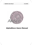
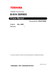
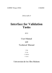
UP3 Education Kit
Reference Manual,Cyclone Edition
Version 01
August 2004
System Level Solutions Inc. (USA)
14702 White Cloud Ct.
Morgan Hill, CA 95037
System Level Solutions (India) Pvt. Ltd
9/B Radhakrishna Colony,
Mangalpura Road,
Anand - 388001.
UP3 Education Kit
2
System Level Solutions
UP3 Education Kit
Copyright©2004
System Level Solutions, Inc. (SLS) All rights reserved. SLS, an Embedded systems company,
the stylized SLS logo, specific device designations, and all other words and logos that are
identified as trademarks and/or service marks are, unless noted otherwise, the trademarks and
service marks of SLS in India and other countries. All other products or service names are the
property of their respective holders. SLS products are protected under numerous U.S. and foreign patents and pending applications, mask working rights, and copyrights. SLS reserves the
right to make changes to any products and services at any time without notice. SLS assumes
no responsibility or liability arising out of the application or use of any information, products, or
service described herein except as expressly agreed to in writing by SLS. SLS customers are
advised to obtain the latest version of specifications before relying on any published information and before orders for products or services.
System Level Solutions
3
UP3 Education Kit
About this
manual
How to find
the
information
About this manual
This is the first publication of the reference manual of the UP3
(University Program 3) Education Kit published in August, 2004.
•
•
•
4
The Adobe Acrobat Find feature allows you to search the contents of a PDF file. Use Ctrl + F to open the Find dialog box.
Use Ctrl + N to open to the Go To Page dialog box.
Thumbnail icons, which provide miniature preview of each
page, provide a link to the pages.
Links allow you to jump to related information.
System Level Solutions
How to contact SLS
How to
contact SLS
UP3 Education Kit
For the most up-to-date information about SLS products, go to the
SLS worldwide website at http://www.slscorp.com.
TABLE 1. Contact Information
System Level Solutions
Information Type
India & USA
Product literature services, SLS literature
services, Non-technical customer services.
http://www.slscorp.com
Technical support.
[email protected]
5
UP3 Education Kit
6
System Level Solutions
UP3 Education Kit
CONTENTS
ABOUT THIS MANUAL ...............................................................................4
How to find the information ........................................................................4
How to contact SLS ...................................................................................5
Features ...................................................................................................9
General Description.................................................................................10
COMPONENTS .........................................................................................11
Board Diagram ........................................................................................11
UP3 Education Kit ...................................................................................12
The Cyclone EP1C6Q240 Device ..........................................................13
Serial Configuration Device ....................................................................15
Active Serial & JTAG............................................................................15
Flash Memory Device ..............................................................................17
SRAM Device ..........................................................................................20
SDRAM Device .......................................................................................22
Liquid Crystal Display ..............................................................................25
LCD Initialization .................................................................................28
Initializing by instruction...................................................................28
Expansion Prototype connector .............................................................32
IDE .......................................................................................................... 38
Serial Port Connector .......................................................................39
I2C Bus ....................................................................................................41
I2C Memory (EEPROM) .....................................................................42
I2C RTC ................................................................................................42
USB ........................................................................................................44
B Type Connector ................................................................................44
PHY-Chip ..............................................................................................44
PS/2 Connector ......................................................................................46
Parallel Port .............................................................................................47
VGA Port .................................................................................................49
Push Button Switches .............................................................................51
Dip Switches ...........................................................................................52
LEDs ........................................................................................................53
Power Supply Circuitry ............................................................................54
Power Supply Configuration Jumper ...................................................54
Clock Circuitry ........................................................................................55
Reset Circuitry ........................................................................................59
System Level Solutions
7
UP3 Education Kit
8
System Level Solutions
Features
Features
UP3 Education Kit
The following are some of the features of the UP3 Education Kit.
•
•
•
•
•
•
•
•
•
•
•
•
•
•
•
•
•
•
•
•
System Level Solutions
Features an Altera EP1C6Q240 Device and EPCS1 configuration devices
Supports intellectual property based(IP-Based) design both
with and without a microprocessor
USB 1.1 (Full speed & Low speed)
RS 232 Port (Full Modem)
Parallel port (IEEE1284)
PS/2 Port
VGA port
IDE (Integrated Drive Electronics)
128KBytes of SRAM (64K X 16)
2MBytes of FLASH (1M X 16)
8MByte SDRAM (4M X 16)
2KBytes of I2C PROM (Expandable)
Supports multiple clocks like PCI clock, USB clock, IOAPIC
clock and CPU clock.
JTAG and Active Serial download capability
5V Santa Cruz long Expansion Card Header provides 72 I/O for
the development of additional boards providing various funtionalities
One user definable 4-bit switch block
Four user definable push button switches, and one global reset
switch
Four user definable LEDs
One 16X2 character display LCD Module
I2C Real Time Clock
9
UP3 Education Kit
General
Description
10
General Description
The UP3 Education Kit provides a powerful educational support and
also a low-cost solution for prototyping and rapidly developing products. The board serves as an excellent means for system prototyping, emulation and hardware as well as software development. The
board comes with a powerful Altera Cyclone FPGA. It gives scope to
a hardware design engineer to design, prototype and test IP cores or
any hardware design using HDLs like Verilog or VHDL. The entire
environment helps to quickly implement any processor as well as
any real time operating system on the kit. Along with that one can
simulate and test ‘C’ or assembly code also. The board has industry
standard interconnections, Memory Subsystem, Multiple clocks for
system design, JTAG Configuration, expansion headers for greater
flexibility and capacity and additional user interface features. The
board can be used for DSP applications by interfacing directly to a
DSP processor or implementing DSP functions inside the FPGA. In
short, it is a dual-purpose kit, which can be used for prototyping and
developing VLSI designs as well as designing and developing microprocessor based embedded system designs.
System Level Solutions
Components
UP3 Education Kit
Components
Board
Diagram
System Level Solutions
Figure 1 shows the top view of the board.
FIGURE 1. UP3 Board Top View (not to scale)
11
UP3 Education Kit
UP3
Education Kit
UP3 Education Kit
This section contains a brief overview of the important components
on the UP3 Board. Figure 2 shows the snapshot of the same.
FIGURE 2. UP3 Board Components
12
System Level Solutions
The Cyclone EP1C6Q240 Device
The Cyclone
EP1C6Q240
Device
UP3 Education Kit
U11 is an ALTERA Cyclone EP1C6Q240 in a 240-pin in a PQFP.
Table 2 lists the Cyclone device features.
TABLE 2. Cyclone EP1C6Q240 Device features
Logic Elements
5980
RAM Blocks
20
Total RAM Bits
92160
PLLS
2
Maximum User I/Os
185
FPGA uses SRAM cells to store configuration data. Since SRAM
memory is volatile configuration data must be downloaded to
Cyclone FPGA each time the device powers up. There are three
methods to configure the device Active serial configuration, Passive
serial configuration, JTAG- based configuration. The UP3 board supports two modes.
Active Serial Mode:
Active serial configuration is carried out through serial configuration
device EPCS1.
Serial configuration devices provide a serial interface to access configuration data. During device configuration, Cyclone FPGA read
configuration data via the serial interface, decompresses data if necessary, and program their SRAM cells. This scheme is referred to as
an AS configuration scheme because the FPGA controls the configuration interface. The Quartus II software automatically generates
.pof files that can be downloaded into the configuration device using
Byte-Blaster II for Active serial configuration.
JTAG Mode:
JTAG (Joint Test Action Group) interface. JTAG has developed a
specification for boundary-scan testing. This boundary-scan test
System Level Solutions
13
UP3 Education Kit
The Cyclone EP1C6Q240 Device
(BST) architecture offers the capability to efficiently test components
on printed circuit boards (PCBs) with tight lead spacing. The BST
architecture can test pin connections without using physical test
probes and capture functional data while a device is operating normally. The user can also use the JTAG circuitry to shift configuration
data into Cyclone FPGA. The Quartus II software automatically generates .sof files that can be downloaded using Byte-Blaster II for
JTAG configuration.
Cyclone is designed such that JTAG instructions have precedence
over any device operating modes. So JTAG configuration can take
place without waiting for other configuration to complete (e.g., configuration with serial or enhanced configuration devices). If the user
attempt JTAG configuration in Cyclone FPGA during non-JTAG configuration, non- JTAG configuration will be terminated and JTAG configuration will be initiated.
Passive configuration mode has not been supported here. This
board does not support multiple devices using Active Serial mode.
FIGURE 3. EP1C6Q240 Cyclone FPGA
EP1C6Q240
14
System Level Solutions
Serial Configuration Device
Serial
Configuration
Device
UP3 Education Kit
U15 is a serial configuration device (EPCS1) for the Cyclone FPGA
on UP3 board. Serial configuration devices are flash memory
devices with a serial interface that can store configuration data for a
Cyclone device and reload the data to the device upon power-up or
re-configuration. With the new data-decompression feature in the
Cyclone FPGA family, designers can use smaller serial configuration
device to configure larger Cyclone FPGA.
Active Serial & JTAG:
On UP3 board AS configuration scheme is combined with JTAGbased configuration. The MSE (Mode Select Enable) pins are tied
low to select the Active Serial Configuration mode. This setup uses
two 10-pin download cable headers on the board. The first header
(JP11) programs the serial configuration device in-system via the AS
programming interface, and the second header (JP12) configures
the Cyclone FPGA directly via the JTAG interface. If you try configuring the device using both schemes simultaneously, JTAG configuration takes precedence and AS configuration will be terminated..
TABLE 3. Header JP12
Header JP12 Pin No.
System Level Solutions
Signal
FPGA (U11) Pin No
1
TCK
147
2
GND
---
3
TDO
149
4
+3.3V
---
5
TMS
148
6
+3.3V
---
7
NC
---
8
NC
---
9
TDI
155
10
GND
---
15
UP3 Education Kit
Serial Configuration Device
TABLE 4. Header JP11
Header (JP11) Pib No.
Signal
EPCS1
(U15) Pin
No.
1
DCLK
6
36
2
GND
---
---
3
CONF_DONE
---
1454
4
+3.3V
---
---
5
CONFIG#
---
25
6
CE#
---
32
FPGA (U11)
Pin No.
7
DATA
2
25
8
CSO#
1
24
9
ASDO
5
37
10
GND
---
---
FIGURE 4. Active Serial & JTAG Header
JTAG
Header
AS
Header
16
System Level Solutions
Flash Memory Device
Flash
Memory
Device
UP3 Education Kit
U8 is a 2Mbyte of Flash memory (TC58FVB160AFT-70) connected
to the Cyclone device.
The TC58FVT160/B160A is a 16,777,216-bit, 3.0-V read-only electrically erasable and programmable flash memory organized as
2,097,152 words x 8 bits or as 1,048,576 words x 16 bits. The
TC58FVT160/B160A features commands for Read, Program and
Erase operations to allow easy interfacing with microprocessors. The
Program and Erase operations are automatically executed in the
chip. Table 5 shows the Flash signal description and its connection
with FPGA.
FIGURE 5. Flash Memory Devices
Flash
Memory
System Level Solutions
17
UP3 Education Kit
Flash Memory Device
TABLE 5. Flash Signal Description
18
Flash Pin
Signal
Name
FPGA Pin No.
Descritpion
1
A15
76
Address Line
2
A14
75
Address Line
3
A13
75
Address Line
4
A12
68
Address Line
5
A11
67
Address Line
6
A10
66
Address Line
7
A9
65
Address Line
8
A8
64
Address Line
9
A19
78
Address Line
10
NC
---
Not Connected
11
WE#
79
Write Enable Signal
12
RESET
----
System Reset
13
NC
----
Not Connected
14
NC
----
Not Connected
15
RY/BY#
80
Ready/Busy Signal
16
A18
81
Address Line
17
A17
82
Address Line
18
A7
63
Address Line
19
A6
83
Address Line
20
A5
84
Address Line
21
A4
85
Address Line
22
A3
86
Address Line
23
A2
87
Address Line
24
A1
88
Address Line
25
A0
93
Address Line
26
CE#
117
Chip Enable Signal
27
VSS
---
GND
28
OE#
118
O/P Enable Signal
29
DQ0
94
Data Line
30
DQ8
95
Data Line
System Level Solutions
Flash Memory Device
UP3 Education Kit
TABLE 5. Flash Signal Description
System Level Solutions
Flash Pin
Signal
Name
FPGA Pin No.
Descritpion
31
DQ1
96
Data Line
32
DQ9
97
Data Line
33
DQ2
98
Data Line
34
DQ10
99
Data Line
35
DQ3
100
Data Line
36
DQ11
101
Data Line
37
VDD
---
Data Line
38
DQ4
102
Data Line
39
DQ12
103
Data Line
40
DQ5
104
Data Line
41
DQ13
105
Data Line
42
DQ6
106
Data Line
43
DQ14
107
Data Line
44
DQ7
113
Data Line
45
DQ15/A-1
114
Data Line / Address Line
46
VSS
---
GND
47
BYTE
115
Word / Byte
48
A16
77
Address Line
19
UP3 Education Kit
SRAM Device
SRAM Device
U7 is the 128KBytes asynchronous SRAM (IS61C6416) device. It is
a high speed, 1,048,576-bit static RAM organized as 65,536 words
by 16 bits. It is fabricated using the ISSI’s high performance CMOS
technology. This highly reliable process coupled with innovative circuit design techniques, yields access times as fast as 10 ns with low
power consumption. Table 6 describes signals and pin connections
of SRAM..
TABLE 6. Pin Out for SRAM
20
SRAM Pin
No.
Signal
Name
FPGA Pin No.
Description
1
AD-15
76
Address Line
2
AD-14
75
Address Line
3
AD-13
74
Address Line
4
AD-12
68
Address Line
5
AD-11
67
Address Line
6
CE_n
116
7
DQ-00
94
Data Line
8
DQ-01
96
Data Line
9
DQ-02
98
Data Line
10
DQ-03
100
Data Line
11
VCC
---
Supply
12
GND
---
GND
13
DQ-04
102
Data Line
14
DQ-05
104
Data Line
15
DQ-06
106
Data Line
16
DQ-07
113
Data Line
17
WE_n
79
Write Enable Input
18
AD-10
66
Address Line
19
AD-09
65
Address Line
20
AD-08
64
Address Line
21
AD-07
63
Address Line
22
NC
---
Not Connected
23
NC
---
Not Connected
24
AD-06
83
Address Line
System Level Solutions
SRAM Device
UP3 Education Kit
TABLE 6. Pin Out for SRAM
SRAM Pin
No.
Signal
Name
FPGA Pin No.
Description
25
AD-05
84
Address Line
26
AD-04
85
Address Line
27
AD-03
86
Address Line
28
NC
---
Not Connected
29
DQ-08
95
Data Line
30
DQ-09
97
Data Line
31
DQ-10
99
Data Line
32
DQ-11
101
Data Line
33
VCC
---
Supply
34
GND
---
GND
35
DQ-12
103
Data Line
36
DQ-13
105
Data Line
37
DQ-14
107
Data Line
38
DQ-15
114
Data Line
39
LB_n
77
Lower Byte Control
40
UB_n
82
Upper Byte Control
41
OE_n
118
Output Enable Input
42
AD-02
87
Address Line
43
AD-01
88
Address Line
44
AD-00
93
Address Line
FIGURE 6. SRAM Device
Flash Memory
SRAM
System Level Solutions
21
UP3 Education Kit
SDRAM
Device
SDRAM Device
U6 is a 8MByte Synchronous Dynamic RAM (IS42S16400B). It is
organized as 1,048,576 bits X 16-bit X 4-bank for improved performance. The synchronous DRAMs achieve high speed data transfer
using pipeline architecture. All the input and output signals refer to
the rising edge of the clock input. Figure 7 below shows the pin configuration of the SDRAM and the figure 8 shows the SDRAM device.
Table 7 gives the pin description for the same.
TABLE 7. SDRAM Pin Configuration
22
SDRAM
Pin No.
Signal Name
FPGA Pin
No.
Description
1
VDD
---
Supply
2
DQ-00
94
Data Line
3
VDDQ
---
Supply
4
DQ-01
96
Data Line
5
DQ-02
98
Data Line
6
GNDQ
-
GND
7
DQ-03
100
Data Line
8
DQ-04
102
Data Line
9
VDDQ
---
Supply
10
DQ-05
104
Data Line
11
DQ-06
106
Data Line
12
GNDQ
---
GND
13
DQ-07
113
Data Line
14
VDD
---
Supply
15
LDQM
77
Lower Byte, I/O Mask
16
WE_n
79
Wrtie Enable Input
17
CAS_n
75
Column Address Strobe
18
RAS_n
76
Row Address Strobe
19
CE_n
119
Chip Enable Input
20
BA0
68
Bank Select Address
21
BA1
74
Bank Select Address
22
AD-10
66
Address Line
23
AD-00
93
Address Line
24
AD-01
88
Address Line
System Level Solutions
SDRAM Device
UP3 Education Kit
TABLE 7. SDRAM Pin Configuration
System Level Solutions
SDRAM
Pin No.
Signal Name
FPGA Pin
No.
Description
25
AD-02
87
Address Line
26
AD-03
86
Address Line
27
VDD
---
Supply
28
GND
---
GND
29
AD-04
85
Address Line
30
AD-05
84
Address Line
31
AD-06
83
Address Line
32
AD-07
63
Address Line
33
AD-08
64
Address Line
34
AD-09
65
Address Line
35
AD-11
67
Address Line
36
NC
---
No Connection
37
CKE
115
Clock Enable
38
CLK
11
SDRAM Clock
39
UDQM
82
Upper Byte, I/O Mask
40
NC
---
No Connection
41
GND
---
GND
42
DQ-08
95
Data Line
43
VDDQ
---
Supply
44
DQ-09
97
Data Line
45
DQ-10
99
Data Line
46
GNDQ
---
GND
47
DQ-11
101
Data Line
48
DQ-12
103
Data Line
49
VDDQ
---
Supply
50
DQ-13
105
Data Line
51
DQ-14
107
Data Line
52
GNDQ
---
GND
53
DQ-15
114
Data Line
54
GND
---
GND
23
UP3 Education Kit
SDRAM Device
FIGURE 7. SDRAM Pin Configuration
Note: To use the SDRAM, apply inverted clock from FPGA to the
SDRAM for the proper SDRAM operations.
FIGURE 8. SDRAM Device
SDRAM
24
System Level Solutions
Liquid Crystal Display
Liquid
Crystal
Display
UP3 Education Kit
U1 is a 16X2 character Liquid Crystal Display (GDM1602A). Here
16X2 represents 2 display lines with 16 characters per line. The display contains 2 internal byte wide registers, one for the command
and second for characters to be displayed. It also contains user programmed RAM area that can be programmed to generate any
desired character that can be formed using a dot matrix. GDM1602A
part is 5V operative so as to connect it to the FPGA, voltage level
shifting is required and this is performed by bus switches
(IDTQS3384).
TABLE 8. Liquid Crystal Display Signal Description
System Level Solutions
LCD Pin No.
Signal Name
FPGA Pin No.
Description
1
VSS
---
GND
2
VDO
---
+5 V
3
VO
---
Contrast Setting
4
RS(Resgister select)
108
All these
5
R/W (Read/
Write
73
All these signals are
6
E(Enable signal)
50
7
DB0
94
and are then con-
8
DB1
96
nected to the FPGA
level shifted
usingIDTQS3384
9
DB2
98
10
DB3
100
11
DB4
102
12
DB5
104
13
DB6
106
14
DB7
113
15
LED+
---
+5V
16
LED-
---
GND
25
UP3 Education Kit
Liquid Crystal Display
Table 8 gives full description about the signals and pin connection of
the LCD.The SRAM devices share address lines with the FLASH
memory and the data lines are shared with the FLASH and LCD
both.
FIGURE 9. LCD
Liquid Crystal Display
26
System Level Solutions
Liquid Crystal Display
UP3 Education Kit
TABLE 9. LCD Instruction Table
CODE
System Level Solutions
Instruct
ion
R
S
R/
W
D
7
D
6
D
5
D
4
D
3
D
2
D1
D0
Execute
Time
(max)
Clear
Display
0
0
0
0
0
0
0
0
0
1
1.64mS
Cursor
at Home
0
0
0
0
0
0
0
0
1
-
1.64mS
Entry
Mode
Set
0
0
0
0
0
0
0
1
I/D
S
40uS
Display
On/Off
Control
0
0
0
0
0
0
1
D
C
B
40uS
Cursor/
Display
Shift
0
0
0
0
0
1
S/
C
R/
L
-
-
40uS
function
set
0
0
0
0
1
D
L
N
F
-
-
40uS
CGRAM
address
set
0
0
0
0
DDRAM
address
set
0
0
1
ADD
40uS
Busy
Flag/
Address
Read
0
1
B
F
AC
40uS
CGRAM
/
DDRAM
Data
Write
1
0
Write Data
40uS
CGRAM
/
DDRAM
Data
Read
1
1
Read Data
40uS
ACG
40uS
27
UP3 Education Kit
Liquid Crystal Display
TABLE 10. LCD Instruction Table
SYMBOLS
DESCRIPTION
SYMBOLS
DESCRIPTION
I/D = 1
Increment
D/L = 0
4 Bit
I/D = 0
Decrement
N=1
1/16 Duty
S=1
With Display
Shift
N=0
1/8 Duty, 1/11 Duty
S/C = 1
Display Shift
F=1
5 X 10 dots
S/C = 0
Cursor Movement
F=0
5 X 7 dots
R/L = 1
Shift to the right
BF = 1
Internal Operation is
being performed
R/L = 0
Shift to the left
BF = 0
New Instruction
D/L = 1
8 Bit
acceptable
The above execution time is for fosc = 250KHz. However, when frequency
changes, execution time also changes. When fosc = 270KHz, then new execution time will be 40uS X (250/270) = 37uS.
LCD Initialization:
Normally LCD itself executes internal reset operations at power up.
But if the power supply condition is not satisfied the internal reset circuit would not operate properly. It is better to provide initialization
sequence by instruction.
Initializing by instruction
POWER ON - 15msec Delay - Function Set - 4.1msec Delay - Function Set - 100microsec - Function Set - 5msec Delay - Function Set Display OFF - Display ON - Entry Mode Set.
LCD on UP3 board is of N = 1 (1/16 Duty) and F = 0 (5X7 dots). After
this sequence LCD is ready for operation.
28
System Level Solutions
Liquid Crystal Display
UP3 Education Kit
TABLE 11. LCD Instruction Table
INSTRUCTION
System Level Solutions
DESCRIPTION
Clear Display
Clears all display and returns the cursor to the home position (Address 0).
Cursor at Home
Returns the cursor to the home position (Address 0). Also
returns the display being shifted to the original position.
DDRAM contents remain unchanged.
Entry Mode Set
Sets the cursor move direction and specifies or not to shift
the display. These operations are performed during data
write and read.
Display On / Off
Control
Sets On/Off of all diaplay(D), cursor On/Off(C), and blink of
cursor position character(B).
Cursor / Display
Shift
Moves the cursor and shifts the display without changing
DDRAM contents.
Function Set
Sets interface data length(DL), number of display lines(L)
and character font(F).
CGRAM
Address Set
Sets the CGRAM address. CGRAM data is sent and
received after this setting.
DDRAM
Address Set
Sets the DDRAM address. DDRAM data is sent and
received after this setting.
Busy Flag /
Address Read
Reads Busy flag(FB) indicating internal operation is being
performed and reads address counter contents.
CGRAM /
DDRAM Data
Write
Writes data into DDRAM or CGRAM
CGRAM /
DDRAM Data
Read
Reads data from DDRAM or CGRAM
29
UP3 Education Kit
Liquid Crystal Display
TABLE 12. Shared Lines on the UP3 board
Signal Name
30
FPGA Pin
No.
SRAM
SDRAM
FLASH
LCD
11
---
SDRAM CLK
---
---
63
AD-07
AD-07
AD-07
---
64
AD-08
AD-08
AD-08
---
65
AD-09
AD-09
AD-09
---
66
AD-10
AD-10
AD-10
---
67
AD-11
AD-11
AD-11
---
68
AD-12
BA0
AD-12
---
74
AD-13
BA1
AD-13
---
75
AD-14
CAS
AD-14
---
76
AD-15
RAS
AD-15
---
77
LB
LDQM
AD-16
---
78
---
---
AD-19
---
79
WE_n
WE_n
WE_n
---
80
---
---
RY/BY_n
---
81
---
---
AD-18
---
82
UB
UDQM
AD-17
---
83
AD-06
AD-06
AD-06
---
84
AD-05
AD-05
AD-05
---
85
AD-04
AD-04
AD-04
---
86
AD-03
AD-03
AD-03
---
87
AD-02
AD-02
AD-02
---
88
AD-01
AD-01
AD-01
---
93
AD-00
AD-00
AD-00
---
94
DQ-00
DQ-00
DQ-00
DQ-00
95
DQ-08
DQ-08
DQ-08
---
96
DQ-01
DQ-01
DQ-01
DQ-01
97
DQ-09
DQ-09
DQ-09
---
98
DQ-02
DQ-02
DQ-02
DQ-02
System Level Solutions
Liquid Crystal Display
UP3 Education Kit
TABLE 12. Shared Lines on the UP3 board
Signal Name
FPGA Pin
No.
System Level Solutions
SRAM
SDRAM
FLASH
LCD
99
DQ-10
DQ-10
DQ-10
---
100
DQ-03
DQ-03
DQ-03
DQ-03
101
DQ-11
DQ-11
DQ-11
---
102
DQ-04
DQ-04
DQ-04
DQ-04
103
DQ-12
DQ-12
DQ-12
---
104
DQ-05
DQ-05
DQ-05
DQ-05
105
DQ-13
DQ-13
DQ-13
---
106
DQ-06
DQ-06
DQ-06
DQ-06
107
DQ-14
DQ-14
DQ-14
---
113
DQ-07
DQ-07
DQ-07
DQ-07
114
DQ-15/A-1
DQ-15/A-1
DQ-15/A-1
---
115
---
CKE
BYTE_n
---
116
CE_n
---
---
---
117
-
---
CE_n
---
118
OE_n
---
OE_n
---
119
-
CE_n
---
---
31
UP3 Education Kit
Expansion
Prototype
Connector
Expansion Prototype Connector
Headers J1, J2, J3 and J4 collectively form the standard-footprint
mechanically stable connections that can be used as an interface to
a special function daughter card.
The expansion prototype connector interface includes
1. 72 pins for prototyping. All 72 I/O pins connect to user I/O pins
on the Cyclone device.
2. PCI Clock appears across J4 from master clock chip.
3. User clock appears across J4 from FPGA.
4. An Active LOW Power On Reset signal.
5. Five regulated 3.3V power-supply pins (1A total max load).
6. One regulated 5V power-supply pin. (1A total max load).
7. Numerous ground connections.
The output logic level on the expansion prototype connector pins is 5
Volt. There are two form of Santa Cruz headers. Short-header and
long-expansion header. In short-header there are J2, J3 & J4 connectors which are 14pins, 40pins and 20pins respectively. Where as
long expansion header has additional connector J1 having 40pins.
The UP3 Kit Santa Cruz Long header provides 72 I/O pins (5 Volt tolerant) for expansion purposes. Here all 72 I/O lines are buffered and
level shifted using bus switches. Figure 10 shows the Santa Cruz
connector.
32
System Level Solutions
Expansion Prototype Connector
UP3 Education Kit
FIGURE 10. Santa Cruz Connector
J3
Pin1
J2
Pin1
J4
Pin1
J1 Pin1
Figure 11, Figure 12, Figure 13 & Figure 14 show the pin description
of the connectors J1, J2, J3 & J4 respectively.
System Level Solutions
33
UP3 Education Kit
Expansion Prototype Connector
FIGURE 11. Expansion Prototype Connector-J1
34
System Level Solutions
Expansion Prototype Connector
UP3 Education Kit
FIGURE 12. Expansion Prototype Connector-J2
System Level Solutions
35
UP3 Education Kit
Expansion Prototype Connector
FIGURE 13. Expansion Prototype Connector-J3
* should be kept NC for standard Santa Cruz connector
36
System Level Solutions
Expansion Prototype Connector
UP3 Education Kit
FIGURE 14. Expansion Prototype Connector-J4
In the figure 14,
•
•
•
System Level Solutions
Connector pin 9 indicates clock from board oscillator
Connector pin 11 directs the clock from PLD
Connector pin 12 refers to the clock output from protocol to
PLD
37
UP3 Education Kit
IDE
IDE
J3 on Santa-Cruz connector can be used as IDE interface connector.
Floppy Drive, Hard Drive and CD ROM Drive usually connect to the
computer through an Integrated Drive Electronics (IDE) interface.
Essentially, an IDE interface is a standard way for a storage device
to connect to a computer.
Table 13 gives the pin connections of IDE.
TABLE 13. IDE
38
FPGA
Pin No.
Signal
---
RESET#
1
217
D7
3
Signal
FPGA
Pin No.
2
GND
---
4
D8
220
IDE Pin No. (S.C. J3)
216
D6
5
6
D9
219
215
D5
7
8
D10
218
206
D4
9
10
D11
221
207
D3
11
12
D12
222
208
D2
13
14
D13
223
213
D1
15
16
D14
224
214
D0
17
18
D15
225
---
GND
19
20
NC
---
199
DMARQ
21
22
GND
---
200
WE#
23
24
GND
---
201
OE#
25
26
GND
---
202
IORDY
27
28
CSEL
196
203
DMACK
29
30
GND
204
INTRQ
31
32
IOCS16
197
205
A0
33
34
PDIAG
179
176
A1
35
36
A2
178
174
CS0#
37
38
CSI
124
173
DASP#
39
40
GND
---
System Level Solutions
Serial Port Connector
Serial Port
Connector
UP3 Education Kit
SER2 is the standard DB-9 Serial connector. It has all 9-pin connections to the FPGA, a FULL Modem interface. This connector is typically used for communication with a host computer using a standard
serial cable connected to (for example) a COM port. U21 (MAX
3243) is a level translator for interfacing the SER2, Full Modem serial
port, with the FPGA.
Figure 15 shows Serial Port connector. Table 14 shows the pin
description of the Serial Port connector.
FIGURE 15. Serial Port Connector
Serial
Port
Connector
System Level Solutions
39
UP3 Education Kit
Serial Port Connector
TABLE 14. Pin Description for Serial Port
40
FPGA Pin
No.
DB-9
(SER2) Pin
No.
Description
---
1
DCD-232 LEVEL
4
RSIN1
---
2
RX-232 LEVEL
6
RSIN2
---
3
TX-232 LEVEL
9
RSOUT1
U21 (MAX 3243)
Pin No.
---
4
DTR-232 LEVEL
10
RSOUT2
---
5
GND-232 LEVEL
25
GND
---
6
DSR-232 LEVEL
5
RSIN2
---
7
RTS-232 LEVEL
11
RSOUT3
---
8
CTS-232 LEVEL
7
RSIN4
---
9
RI-232 LEVEL
8
RSIN5
39
---
DCD-TTL LEVEL
19 TTLOUT1
42
---
RX-TTL LEVEL
17 TTLOUT3
47
---
TX-TTL LEVEL
14
TLIN1
46
---
DTR-TTL LEVEL
13
TTLIN2
---
---
GND-TTL LEVEL
25
GND
41
---
DSR-TTL LEVEL
18 TTLOUT2
45
---
RTS-TTL LEVEL
12
TTLIN3
43
---
CTS-TTL LEVEL
16
TLOUT4
44
---
RI-TTL LEVEL
15 TTLOUT5
System Level Solutions
I2C Bus
I2C Bus
UP3 Education Kit
I2C is a two-wire, bi-directional serial bus that provides a simple and
efficient method of data exchange between devices. It is most suitable for short distance communication between many devices. I2C
standard is a true multi-master bus, which includes collision detection, and arbitration that prevents data corruption if two or more masters attempt to control the bus simultaneously.
It is the most widely used bus, which allows the connection of many
types of ICs that are used in a number of different applications. It provides an interface between microprocessor and peripheral devices
without wiring full address, data and control.
Two I2C buses have been provided on the UP3 board in which one
I2C hooks up with memory (IS24C16 [EEPROM]) and other to RTC
(M41T00). Both are 5V operative. These two buses are
1. Fast I2C Bus: 400Kbps, EEPROM is on this bus
2. Normal I2C Bus: 100Kbps, RTC is on this bus
TABLE 15. I2C Signal Assignments
System Level Solutions
Header Pin
No.
Signal
FPGA Pin No.
---
A0
---
---
A1
---
---
A3
---
---
GND
---
JP18.3
SDA
21
JP18.2
SCL
20
---
WP
---
---
VCC
---
41
UP3 Education Kit
I2C Bus
I2C Memory (EEPROM)
U16 is a 16 Kbits serial EEPROM (IS24C16). Headers are also provided for this I2C bus.
1. Address lines A0,A1,A2 are shoted to GND.
2. SDA and SCL lines are pulled high through 5.6K resistors.
3. Write Protect pin is left floating, not to write protect the memory.
It can be tied HIGH with 5.6Kohm resistor to write protect the upper
half of the memory.
I2C RTC
U5 is a Real Time Clock chip (M41T00) on I2C bus. The M41T00
TIMEKEEPER RAM is a low power Serial TIMEKEEPER with a builtin 32.768kHz oscillator (external crystal controlled). Eight bytes of
the RAM are used for the clock/calendar function and are configured
in binary coded decimal (BCD) format. Addresses and data are
transferred serially via a two-line bi-directional bus. The built-in
address register is incremented automatically after each WRITE or
READ data byte. The M41T00 clock has a built-in power sense circuit that detects power failures and automatically switches to the battery supply during power failures. The energy needed to sustain the
RAM and clock operations can be supplied from a small lithium coin
cell. Typical data retention time is in excess of 5 years with a 50mA/h
3V lithium cell.
1. On UP3 board the RTC is battery backed with 3 V lithium cell.
2. 32.768 KHz crystal is used for the RTC.
3. FT/OUT pin is taken out on the header at JP13.1 for frequency
test.
4. Clock, Data and FT/OUT lines are pulled up through 5.6K resistors.
42
System Level Solutions
I2C Bus
UP3 Education Kit
TABLE 16. RTC Pin Configuration
U5-RTC Pin
No.
Header Pin No.
Signal
FPGA Pin No.
1
---
OSC1
---
2
---
OSC1
---
3
---
VBAT
---
4
---
GND
---
5
JP18.4
SDA
121
6
JP18.5
SCL
120
7
JP13.1
FT/OUT
---
8
---
VCC
---
Headers for I2C bus (JP18)
Signals for both the I2C buses are taken out as headers. These
headers can be used to connect another I2C slaves or can be used
for debug purpose for existing I2C slaves (RTC and PROM).
TABLE 17. Headers for I2C Bus
System Level Solutions
JP18 Pin No.
Signal Description
1
GND
2
SCL - I2C Bus on which RTC is connected
3
SDA - I2C Bus on which RTC is connected
4
SDA - I2C Bus on which PROM is connected
5
SCL - I2C Bus on which PROM is connected
6
VCC +5 Volt
43
UP3 Education Kit
USB
USB
USB is a cable bus that supports data exchange between a host
computer and a wide range of simultaneously accessible peripherals. The attached peripherals share USB bandwidth through a hostdetached while the host and other peripherals are in operation.
The USB transfers signal and power over a four-wire cable as shown
in the figure below. The signaling occurs over two wires on each
point-to-point segment.
B Type Connector
The figure beside shows B-Type connector (J12 on
the UP3 board). This connector requires a transceiver
(PHY-chip) in order to communicate with FPGA.Table
17 shows pin connections of the B- type connector and
Table 18 describes the configuration jumpers.
PHY-Chip
U22, PHY Chip (1T11A) is the intermediate between FPGA & the two
differential lines. It converts the differential line in the three transmit
and three receive signals as shown in the figure 16.
FIGURE 16. USB PHY Chip interface diagram
44
System Level Solutions
USB
UP3 Education Kit
TABLE 18. Connection table B Type Connector to PHY Chip to FPGA
B-Type
Connector
Pin no.
Signal
PHY
Chip Pin
No.
---
Signal
FPGA Pin No.
---
1
Mode
---
---
---
2
OE
16
---
---
3
RCV
17
---
---
4
VP
18
---
---
5
VM
19
---
---
6
SUSPEND
---
J12.4
GND
7
GND
---
J12.1
NC
8
NC
---
---
---
9
SPEED
---
J12.2
D-
10
D-
---
J12.3
D+
11
D+
---
---
---
12
VPO
15
---
---
13
VMO/FSEO
14
---
---
14
VCC
---
TABLE 19. USB Configuration Jumpers
Mode Select
System Level Solutions
Speed Select
Low
Speed
Full
Speed
Jumper
Mode 0
Mode 1
JP8
Pin 1-2
Pin 2-3
---
---
JP9
---
---
Open
Pin 1-2
JP10
---
---
Pin 1-2
Open
JP11
---
---
Pin 2-3
Pin 1-2
45
UP3 Education Kit
PS/2
Connector
PS/2 Connector
JP1 is a PS/2 Connector. The PS/2 interface allows the connectivity
to a PS/2 device. The connector is a female 6-pin mini din type.
FIGURE 17. PS/2 Connector
PS/2
Connector
TABLE 20. PS/2 Signal Description
46
PS/2 Pin #
Signal
FPGA
Pin No.
Descritpion
1
DATA
13
PS/2 Device Data
2&6
NC
---
---
3
GND
---
---
4
+5 V
---
PS/2 Device Supply
5
CLK
12
PS/2 Device Clock
System Level Solutions
Parallel Port
Parallel
Port
System Level Solutions
UP3 Education Kit
CON1 is a standard DB25 Female parallel port connector.
TABLE 21. Parallel Port Signal Description
Parallel Port Pin No.
Signal
FPGA Pin No.
1
C0
8
2
D0
6
3
D1
1
4
D2
5
5
D3
3
6
D4
240
7
D5
238
8
D6
237
9
D7
239
10
S6
236
11
S7
235
12
S5
234
13
S4
233
14
C1
7
15
S3
2
16
+5 V
---
17
C3
4
18
GND
---
19
GND
---
20
GND
---
21
GND
---
22
GND
---
23
GND
---
24
GND
---
25
GND
---
47
UP3 Education Kit
Parallel Port
FIGURE 18. Parallel Port Connector
Parallel
Port
Connector
48
System Level Solutions
VGA Port
VGA Port
UP3 Education Kit
UP3 board has a standard VGA connector. It contains 5 active signals. Two signals compatible with TTL logic levels, horizontal sync
and vertical sync, are used for synchronization of the video. Three
analog signals with 0.7 to 1.0 volts peak-to-peak levels are used to
control the color.
The color signals are Red, Green, and Blue. They are often collectively referred as the RGB signals. By changing the analog levels of
the three RGB signals all other colors are produced.
FIGURE 19. VGA Port
VGA Port
System Level Solutions
49
UP3 Education Kit
VGA Port
TABLE 22. VGA Port Pin Configuration
VGA Pin No.
50
VGA Interface
FPGA Pin No.
1
Red
228
2
Green
122
3
Blue
170
4
NC
---
5
NC
---
6
GND
---
7
GND
---
8
GND
---
9
NC
---
10
GND
---
11
GND
---
12
NC
---
13
H_sync
227
14
V_sync
226
15
NC
---
System Level Solutions
Push Button Switches
Push Button
Switches
UP3 Education Kit
SW4, SW5, SW6 and SW7 are momentary-contact push-button
switches and are used to provide stimulus to designs in the Cyclone
device. Each switch is connected to the Cyclone general-purpose I/O
pin with pull-up resistor. The Cyclone device pin will see logic ‘0’
when each switch is pressed.
FIGURE 20. Push Button Swithces
Push
Button
Switches
TABLE 23. Push Button Switches Pin Out Table
Button
SW4
SW5
SW6
SW7
FPGA Pin No.
48
49
57
62
SW8 is a global reset switch connected to the RESET IC
(TL775BCP). The RESET IC pin RESETIN# will see logic ‘0’ when
pressed. The output of this RESET IC is (RESET# Active LOW) is
then connected to the FPGA pin U11.23. The Cyclone device pin will
see logic ‘0’ when SW8 is pressed.
System Level Solutions
51
UP3 Education Kit
Dip
Switches
Dip Switches
SW3 is a block of four switches. Each switch is connected to the
Cyclone general-purpose I/O pin with pull-up resistor. The Cyclone
device pin will see logic ‘1’ when switch is in ON condition.
FIGURE 21. Dip Switches
DIP
Switches
TABLE 24. Dip Switches Pin Out Table
Switch
FPGA Pin No.
52
SW 3.1
SW 3.2
SW 3.3
SW 3.4
58
59
60
61
System Level Solutions
LEDs
LEDs
UP3 Education Kit
D3, D4, D5 and D6 are four individual LEDs connected to the
Cyclone device general purpose I/O with current limiting resistors. All
of them are active low driven (Common Anode). The LED will glow
when there is logic ‘0’ at FPGA pin.
TABLE 25. LED Pin Out Table
LED
D3
D4
D5
D6
FPGA Pin No.
56
55
54
53
FIGURE 22. LEDs
LEDs
D8 is Configuration Done LED that indicates successful completion
of downloading process. The CONFIG_DONE pin (U11.145) of the
Cyclone device controls this LED.
D15 is INVALID indication LED that indicates faulty/no connection of
the serial cable at the serial port (SER2). If invalid voltage appears at
any receive lines of the MAX 3243 chip (U21) the LED will glow.
U21.21 pin controls this LED.
System Level Solutions
53
UP3 Education Kit
Power
Supply
Circuitry
Power Supply Circuitry
The UP3 board is powered with number of different regulated supply
voltages.
1. +1.5 Volt is for Cyclone core supply.
2. +3.3 Volt is for Cyclone I/O ring supply.
3. +5 Volt is for 5volt operative devices on the board.
The board accepts +9 Volt unregulated/regulated supply from external source (with center-terminal positive supply).
Debug headers provided for the power supply on the board are
described in Table 26.
TABLE 26. Headers on the board
Header
Purpose
JP6
+5 V regulated supply
JP7
+3.3 V regulated supply
JP8
Unregulated input voltage to the board
JP10
+1.5 V regulated supply
Power Supply Configuration Jumper
The board is provided with jumper setting for input supply to the
board. Jumper pins JP5.2 and JP5.3 are shoted when input supply
from external source is +9 volt regulated/unregulated, which is
default setting on the board. Jumper pins JP5.1 and JP5.2 are shoted when input supply from external source is +5 volt regulated. The
second setting is useful when the 5 Volt regulator chip is not stuffed
on the board.
54
System Level Solutions
Clock Circuitry
Clock
Circuitry
UP3 Education Kit
This development board supports number of IP blocks requiring different frequencies. The UP3 board provides multiple clocks. U18 is a
Master clock chip (PI6C106) which provides different clocks on the
board. The clock chip uses 14.318MHz crystal (Y1) for its inbuilt
oscillator. Table 28 gives pin description of clock chip.
JP3 is a 10-pin header for configuring the input clock to the Cyclone
device at CLK1 or CLK3 pins. J7 is a 3-pin header for configuring the
CPU clock outputs of the clock chip.
1.
2.
3.
4.
System Level Solutions
PCI clock (33.33MHz)
USB clock (48MHz)
IOAPIC clock (14.318MHz) and
CPU clock (100MHz / 66.66MHz).
55
UP3 Education Kit
Clock Circuitry
TABLE 27. Clocking Chip Pin Configuration
56
Clock Chip Pin
No.
Signal
Connection
1
GND1
Board ground
2
X1
Crystal Y 1.1
3
X2
Crystal Y 1.2
4
GND2
Board ground
5
PCICLK F
Clock setting Jumper JP 3.7
6
PCICLK F
NC
7
PCICLK0
Cyclone CLK0 (U 11.28)
8
PCICLK1
NC
9
VDD2
+3.3 Volt Supply
10
PCICLK2
Santa Cruz Connector J4.9
11
PCICLK3
NC
12
PCICLK4 /
SEL100/66#
CPU clock select jumper J7.2
13
VDD3
+3.3 Volt Supply
14
48 MHz
Clock Setting Jumper JP 3.3
15
GND3
Board ground
16
SPREAD#
Tied high +3.3 Volt
17
PD#
Tied high +3.3 Volt
18
CPU_STOP#
Cyclone U 11.123
19
PCI_STOP#
Cyclone U 11.122
20
GND
Board ground
21
VDDLC
+3.3 Volt Supply
22
CPUCLK2
Clock header Jp 4.1
23
CPUCLK1
NC
24
CPUCLK0
Cyclone CLK2 (U 11. 153)
25
VDDLA
+3.3 Volt Supply
26
IOAPIC
Clock header JP 19.1
27
VDD1
+3.3 Volt Supply
28
REF0
Clock setting Jumper Jp3.6
System Level Solutions
Clock Circuitry
UP3 Education Kit
Table 28 describes jumper setting for CLK1, table 29 describes
jumper setting for CLK3 and table 30 is for CPU clock select setting.
Table 31 describes details of other clock headers. Table 32 describes
the external clock input that can be adjusted by the user.
TABLE 28. Jumper Setting for Clock Input to the FPGA at CLK1
CLK1
Jumper Setting
FPGA Pin
No.
USBCLK (U18.14) 48 MHz
Shot JP3.4-JP3.3
29
REF0CLK (U18.28) 14.318 MHz
Shot JP3.4-JP3.6
29
TABLE 29. Jumper Setting for Clock Input to the FPGA at CLK3
CLK3
Jumper Setting
FPGA Pin
No.
PCICLK_E (U18.5)3.33MHz
Shot JP3.8 & JP3.7
152
REF0CLK (U18.28) 4.318 MHz
Shot JP3.8 & JP3.6
152
TABLE 30. CPU Clock Select Setting
System Level Solutions
CPU Clock
Jumper Setting
FPGA Pin
No.
66 MHz
Shot JP 7.1 & JP 7.2
153
100 MHz
Shot JP 7.2 & JP 7.3
153
57
UP3 Education Kit
Clock Circuitry
TABLE 31. Other Clock Header
Header
Signal
JP 4.1
CPUCLK2 ( U18.22)(100MHz) as per Jumper Setting
JP 19.1
IOAPIC (U 18.26)
It is strongly recommended to disable the clocks if not in use, using
CPU_STOP and PCI_STOP signals to disable CPU clocks and PCI
clocks.
TABLE 32. External Clock Input
58
Header
Signal
FPGA Pin No.
JP 2.2
USER CLOCK
38
System Level Solutions
Reset Circuitry
Reset
Circuitry
UP3 Education Kit
U19 (TL7705BCP) is an integrated-circuit supply-voltage supervisor.
The supply-voltage supervisor monitors the supply for under voltage
conditions at the SENSE input. During power up, the RESET output
becomes active (low) when VCC attains a value approaching 1 V. As
VCC approaches 3 V (assuming that SENSE is above VT+), the
delay-timer function activates a time delay, after which outputs
RESET and RESET goes inactive. When an under voltage condition
occurs during normal operation, outputs RESET and RESET goes
active. To ensure that a complete reset occurs, the reset outputs
remain active for a time delay after the voltage at the SENSE input
exceeds the positive-going threshold value.
TABLE 33. Reset Signal Assignment
System Level Solutions
U19 Reset IC
Pin No.
Signal
FPGA Pin No.
Connection
1
REF
---
---
2
RESETIN#
---
SW8
3
CT
---
---
4
GND
---
---
5
RESET#
23
---
6
RESET
---
NC
7
SENCE +5 V
---
---
8
VCC +5 V
---
---
59