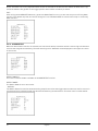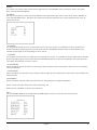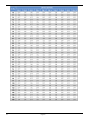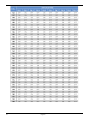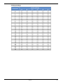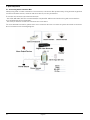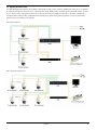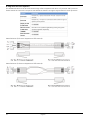
1
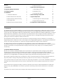
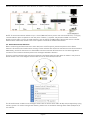
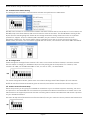
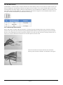
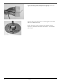
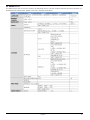
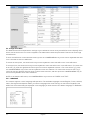
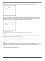
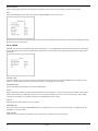
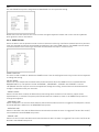
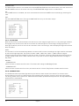
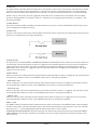
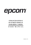
Owner´s Manual
Motorized Dome Cameras
GCA-C0335P
GCA-C0335P.28.1.10.08.2011
© ASP AG
Motorized Dome Day/Night Camera, 12x Zoom, WDR
Content:
6. Cable Connection
5
1. Introduction
1
5. Operation and Configuration
9
2. Important Safety Instructions
1
1. OSD Display Format
9
3. Package Contents
2
2. OSD Menu Tree
10
4. Installation
2
3. Configuration Menu
13
1. Installation Remarks
2
6. Switch Settings Index Table
35
2. Switch & Connector Definition
3
7. System Expansion
43
3. Communication Switch Setting
4
1. Connecting with a Connector Box
43
4. ID Configuration
4
2. Signal Distribution Unit
44
5. Camera Control Protocol Setup
4
8. Integration of a Pelco Keyboard
45
1. Introduction
The Swiftdome Camera GCA-C0335P is an innovative Dome Camera designed for middle and small surveillance
applications and possesses true Swiftdome Camera features, such as high speed and accurate Pan/Tilt, up to
12×12 zoom ratio, 180° Digital Image Flip, Speed by Zoom, and Preset Speed up to 400°/s. Additionally, it contains
256 Preset Points, 8 Sequence Lines, 4 Auto Pan Lines and 8 Cruise Lines to support automatic operations. It is
ideal for all surveillance requirements in hotels, department stores, intelligent buildings, amusement parks,
parking lots, factories, hospitals, schools, stations etc.
This Swiftdome Camera contains various solutions for low light and high contrast conditions. For example, a
bright background or shade can result in the subject of the image appearing darker. The backlight compensation
function can solve this problem for it produces a bright and beautiful image in these conditions.
The Dome Camera supports one cabling for easy installation, and can be combined with various digital
surveillance products, such as DVRs, Control Keyboards and various sorts of accessories for a total surveillance
solution. The camera is incorporated with multiple protocols: Pelco, VCL, Philips, etc. to enhance powerful
connectivity.
2. Important Safety Instructions
Be sure to use only the standard adapter that is specified in the specification sheet. Using any other adapter
could cause fire, electrical shock, or damage to the product. Incorrectly connecting the power supply or
replacing battery may cause explosion, fire, electric shock, or damage to the product. Do not connect multiple
products to one single adapter. Exceeding the capacity may cause abnormal heat generation or fire.
Do not place conductive objects (e.g. screwdrivers, coins or any metal items) or containers filled with water on
top of the product. Doing so may cause personal injury due to fire, electric shock, or falling objects.
If any unusual smells or smoke come from the unit, stop using the product. In such case, immediately disconnect
the power source and contact the service center. Continued use in such a condition may cause fire or electric
shock.
If this product fails to operate normally, contact the nearest service center. Never disassemble or modify this
product in any way. (GRUNDIG is not liable for problems caused by unauthorised modifications or attempted
repair.)
To prevent fire or electric shock, do not expose the inside of this device to rain or moisture.
English
1
3. Package Contents
These parts are included:
4. Installation
4.1. Installation Remarks
Do not install the product in a location subject to high temperature (over 50°C), low temperature (below -10°C),
or high humidity. Doing so may cause fire or electric shock. Keep out of direct sunlight and heat radiation
sources. It may cause fire. Avoid aiming the camera directly towards extremely bright objects such as sun, as
this may damage the image sensor.
Do not install the unit in humid, dusty or sooty locations. Doing so may cause fire or electric shock. Install it in a
place with good ventilation.
When installing the unit, fasten it securely and firmly. A falling unit may cause personal injury.
If you want to relocate the already installed product, be sure to turn off the power and then move or reinstall it.
If the PTZ system looses its power supply during freezing temperatures and the power supply returns
afterwards, the Swiftdome Camera will first heat up internally to +3° C and then the initialiasition will start. In
this way it can be prevented that the sliding contacts and the motors get damaged through a cold start.
General Operation Requirements:
At least one control device is required for operation, such as a Control Keyboard, a DVR or a PC. The Swiftdome
Cameras contain a built-in receiver that decodes commands originating from a control device.
2
English
Connect the Dome Cameras to other devices, as shown in the diagram, to complete a video surveillance system.
NOTE: To extend the network distance up to 1.2 km (4000 feet) and to protect the connected devices, it is highly
recommended to place a repeater at the mid-point. However, a repeater may be also needed in a network
distance of less than 1.2 km if the used cables are not the CAT 5 / 24 AWG cables (please see section 4.6.4 RS485 Connector Definition). Please refer to the repeater’s manual for detailed information.
4.2. Switch & Connector Definition
Before connecting the Dome Camera to other devices of a CCTV system, please complete first the Dome
Camera’s ID and communication switch settings. These switches are located on the bottom of the Dome Camera.
Additionally, the 22-Pin Connector for Data Cable connection and the ISP Connector for firmware upgrade kit
connection are located on the back plate of the analogue Swiftdome Camera.
There are various switches and connectors located on the Dome Camera’s back plate as shown in the pictures
below. Please refer to the diagram and the table for use of each switch/connector.
The ID and Protocol numbers of an analogue camera are set with a 10-bit and 6-bit dip switch respectively using
a binary system. For switch configuration details, please refer to the Switch Settings Index Table (Chapter 6) in
this manual.
English
3
NOTE: DO NOT change the Swiftdome Camera’s Communication Switch factory default settings.
4.3. Communication Switch Setting
The analogue Dome Camera’s communication switches are specified in the table below.
RS-485 is the interface for communication between the Dome Camera and its control device. For this reason, the
RS-485 setup of the Dome Camera and the control device must be the same. The RS-485 default setting is halfduplex (see the following diagram). Please do not change the default setting without the notice of a qualified
specialist or supplier. As for the switches SW 3 and SW 4, they are used for termination and Line Lock
adjustment respectively. The switch SW 5 is mainly used when users want to restore the camera to factory
default status; moreover, once a firmware upgrade was carried out, users need to reset switch SW 6 afterwards.
4.4. ID Configuration
Please change the analogue Dome Camera’s ID if there is more than one Dome Camera in the same network.
Use this switch to change your Swiftdome Camera’s ID by setting the 10-bit dip switch. For instance, if the
camera’s ID is 006, set the SW 8 and SW 9 to “ON”, the rest to “OFF,” as shown below.
For switch configuration details, please refer to the Switch Settings Index Table (Chapter 6) in this manual.
NOTE: No two Dome Cameras should be given the same ID, otherwise a communication conflict may occur.
4.5. Camera Control Protocol Setup
Define the protocol you are going to use based on the devices of your surveillance system. Generally, the use of
one protocol is recommended even if the devices are provided from different manufacturers. Please refer to the
table below for all supported protocols with their matching switch numbers and baud rate and choose a protocol
for your Swiftdome Camera.
Use the 6-bit dip switch (Camera Control Protocol Switch) to set your camera’s control protocol and its baud rate.
4
English
If you select the protocol Pelco D, which is to be set with switch no. 01 and baud rate 2400, for instance, set the
SW 6 to “ON”, the rest to “OFF,” as shown below.
4.6. Cable Connection
The Dome Camera is supplied with one integrated 22-pin Data Cable for connecting with the power, video, and
RS-485/audio input & audio output cables. Please read the following sections thoroughly before making
connections.
4.6.1. Cable Requirements
For operation, this Dome Camera requires video, RS-485 and power cables as described below:
- The video cable sends video signals to a remote viewing site. Using a coaxial cable to send video signals is
recommended.
- The RS-485 cable carries commands from a control device to the Dome Cameras. A CAT 5 / 24 AWG cable is
recommended.
- Power supply: DC 24V / AC 24V input voltage
NOTE: Please ensure that the power supply meets the Dome Camera’s power requirement, otherwise product
impairment may occur. If any mistake happens, please contact a qualified maintenance engineer.
English
5
4.6.2. 22-Pin Data Cable
The analogue Dome Camera’s Data Cables are illustrated as follows.
NOTE: Be careful not to pull the cables improperly during installation. Additionally, it is recommended to fasten
the cables after cable connection is completed. Furthermore, when wiring the power cable, make sure the
Ground wire is inserted into the mid-pin of the terminal block.
4.6.3. 22-Pin Connector Definition
With the 22-pin connector, installers can simply connect the power, video and RS-485 cables to the Dome
Camera at once. Particularly, the alarm pins are serviceable for connecting alarm input and output devices, such
as alarm sensors, sirens or flashing lights with the surveillance system. For the definition of each pin, please
refer to the tables below.
The analogue Dome Camera’s 22-pin connector definition is listed as follows:
6
English
4.6.4. RS-485 Connector
The RS-485 is a communication interface between the Dome Camera and its control device. Please connect the
Control Keyboard to the Swiftdome Camera through the terminal block. The recommended cables for RS-485
communication are CAT 5 cables; maximum cable length for over 24 AWG wire is 4000 feet (1219 meters). If the
total cable length exceeds 4000 feet, using a repeater to maintain the signals is recommended. Please refer to
the figure and the table below for pin definition and wiring.
4.6.5. Cable Wiring and Connection
Users may need to conduct cable wiring when: (1) Connecting self-provided cords to the connector housing
(shown in the figure below) instead of using the equipped data cable or (2) Connecting alarm input and output
devices. The following pictures will illustrate the way to wire cords into the connector housing. Please refer to
section 4.6.2. 22-Pin Connector Definition for the exact position of each cord.
Insert the terminal into the pin holes on the connector
housing, with the hook outwards, as indicated in the figure.
English
7
To unlock the terminal, press the hook, as indicated in the
figure, with a proper tool and pull it out gently.
Connect the 22-pin connector to its mating port on the back
plate of the Dome Camera.
NOTE: The figure is for illustration only. Please refer to
section 4.2. Switch & Connector Definition for correct back
plate layout.
8
English
5. Operation and Configuration
5.1. OSD Display Format
Regarding information about OSD display, position and function description, please refer to the table below.
9
English
5.2. OSD Menu Tree
The OSD setup menu structure is listed in the following section. The star symbol indicates the factory default. For
detailed function description, please refer to 5.3. Configuration Menu.
English
10
11
English
English
12
5.3. Configuration Menu
The detailed functions and parameter settings of your Swiftdome can be set by the OSD (On Screen Display) menu
with a control device such as a control keyboard. The tables below show the parameters that can be set through
the OSD menu.
To enter the OSD menu of the selected camera, press the <CAMERA MENU> key on the control keyboard and hold
it for 3 seconds to enter the OSD menu.
To select the setup item, use the direction keys on the keyboard to move the OSD cursor in the OSD menu.
To setup an item, use the direction keys on the keyboard to move the OSD cursor in the OSD menu. For items with
an arrow (→), press the right/left direction keys on the control keyboard to select it. For items with a (↓), press
the <CAMERA MENU> key on the control keyboard to enter the submenu. For items with several arrows (→↓),
users can use the right/left direction keys to select these functions, and then press the <CAMERA MENU> key on
the control keyboard to enter their submenus.
NOTE: In the Camera OSD menu, the <CAMERA MENU> key functions as “ENTER” and “EXIT.”
5.3.1. LANGUAGE
The camera supports a multi-language OSD operation. The available languages include English, French, German,
Italian, Portuguese and Spanish. When you select a language with the arrow keys on the Control Keyboard, the
OSD menu will automatically be displayed in the language you have selected. The default language is <ENGLISH>.
13
English
5.3.2. DEFAULT CAMERA
This item is for restoring the camera settings, including Backlight, Focus, AE, WBC, Digital Zoom, Slow Shutter,
Image Inverse and Aperture, to factory defaults. Once one of the parameters mentioned above is modified, the
DEFAULT CAMERA item will turn automatically to <OFF>. Select <ON> to recall the default settings for these
camera parameters.
5.3.3. BACKLIGHT
The Backlight Compensation function prevents the centre object from being too dark in surroundings where
excessive light is behind the centre object.
When you set this item to <ON>, the centre object will be brightened in contrast to the edge of the picture (where
backlight would most likely be located).
After completing the setup of backlight, go back to Main Page 1 and continue to set the focus values.
5.3.4. FOCUS
The Dome Camera’s focus can be operated in two modes: Manual Focus mode and Auto Focus mode.
AUTO:
There are three options available for the AF Mode, including Normal mode, Zoom Trigger (Z. TRIG.) mode and PTZ
Trigger (PTZ TRIG.) mode. The submenu of AUTO is shown below:
- Normal Mode:
In this mode, the camera will stay focussed automatically and continuously in any condition.
- Zoom Trigger Mode (Z. TRIG.):
In this mode, AF is activated at the time when zoom is changed.
- PTZ Trigger Mode (PTZ TRIG):
In this mode, AF is triggered when the Dome Camera is set to pan, tilt or zoom.
- EXIT+SAVE:
Press <YES> to save the selected AF Mode.
English
14
MANUAL:
In this mode, users can adjust the focus to near/far via the control keyboard’s Focus Near/Far key.
5.3.5. AE MODE
Exposure is the amount of light received by the image sensor and is determined by how wide you open the lens
diaphragm (iris adjustment), by how long you keep the sensor exposed (shutter speed), and by other exposure
parameters. With this item, users can define how the Auto Exposure (AE) function works.
EXPOSURE COMPENSATION:
The exposure value ranges from -10.5dB to 10.5dB. Select <OFF> to disable this function.
AE MODE:
- AUTO:
In this mode, the camera’s Brightness, Shutter Speed, IRIS and AGC (Auto Gain Control) control circuits work
together automatically to get consistent video output level.
- SHUTTER:
With this option, Shutter Speed takes main control of exposure, and both IRIS and AGC will function automatically
in cooperation with the shutter speed to achieve consistent exposure output. The shutter speed ranges from
1/10000 to 1/50.
- IRIS:
In this mode, the IRIS function adjusts exposure in higher property. SHUTTER speed and AGC circuit will function
automatically in cooperating with the IRIS to get consistent exposure output. The IRIS value is fixed at f1.6.
- Manual:
In this mode, users can adjust the shutter speed (1/10000 ~ 1/50 for PAL; 1/10000 ~ 1/60 for NTSC) and the gain
value (-3dB ~ 28dB) for optimised video output.
15
English
EXIT:
Exit the AE MODE menu and go back to the Main Page 1 to set the WBC mode.
5.3.6. WBC MODE
A camera needs to find a reference colour temperature, which is a way of measuring the quality of a light source,
for calculating all the other colours. The scale unit for measuring this ratio is in degree Kelvin (K). Users can
select one of the White Balance Control modes according to the operating environment.
Light Sources :
Cloudy Sky (Colour Temperature: 6,000 to 8,000 K)
Noon Sun and Clear Sky (Colour Temperature: 6,500 K)
Household Lighting (Colour Temperature: 2,500 to 3,000 K)
75-watt Bulb (Colour Temperature: 2,820 K)
Candle Flame (Colour Temperature: 1,200 to 1,500 K)
AUTO:
In this mode, white balance works within its colour temperature range. This mode computes the white balance
value output using the colour information from the entire screen. It outputs the proper value using the colour
temperature radiating from a black subject based on a range of values from 3000K to 7500K.
INDOOR:
3200 K Base mode.
OUTDOOR:
5800 K Base mode.
ATW Mode (Auto Tracing White Balance) :
The Dome Camera adjusts the White Balance continously in a range from 2000 K to 10000 K.
MANUAL:
In this mode, users can change the White Balance value manually; R gain and B gain are adjustable and range
from 0 to 127.
English
16
After the parameter setups relevant for WBC are completed, please exit the WBC MODE menu and go back to
Main Page 1 to continue to set other functions under the Setup Menu 1.
5.3.7. SETUP MENU 1
The SETUP MENU 1 is shown below.
The zoom speed of the Dome Camera is fixed (Value: 8). Users can choose to activate functions like Digital Zoom,
Slow Shutter, Noise Reduction, Image Inverse and Image Freeze. Please refer to the following description for use
of each function.
DIGITAL ZOOM:
With this item, users can enable or disable the 12× Digital Zoom. The Digital Zoom will start to activate after the
full Optical Zoom level is reached. A maximum of 12× digital zoom is allowed to be carried out. The default setting
is <ON>.
NOTE: The difference between optical and digital zoom is that the optical zoom uses the lens within the camera to
draw the image closer via zooming in or out for achieving the desired effect. Optical zoom keeps the same
resolution in the zoomed image as there was in the original image, therefore the image quality stays the same. In
contrast, the Digital zoom takes one part of the image and expands that image to the full size of the screen, in
doing so the image quality will be reduced.
SLOW SHUTTER:
The shutter speed determines how long the image sensor is exposed to light. The Dome Camera will
automatically adjust the shutter speed based on the light condition of the operating environment. With the Slow
Shutter function, the camera will still produce a clear image in low light conditions under 0.1 lux.
DIGITAL NOISE REDUCTION (D.N.R.):
With 2D / 3D Noise Reduction, the processor analyses pixel by pixel and frame by frame to eliminate
environmental noise signals so that the highest quality image can be produced, even in low light conditions. In
comparison with 2D D.N.R., the 3D D.N.R generates better denoising effects.
IMAGE INVERSE:
Users can select <ON> to inverse the displayed image vertically and horizontally (please see the figures shown
below). Occasions to employ the function include conferences, demonstration, testing, etc. The default setting is
<OFF>. When this function is enabled, the preset mask(s) will be set off automatically.
17
English
- Application:
Users can see the displayed images, as shown below, when a dome is placed on top of a desk, for instance.
FREEZE:
The Freeze function allows to hold the image while the camera is moving between preset positions like in
PRESET (please refer to 5.3.12) or SEQUENCE (please refer to 5.3.13) mode. For example, when the Dome
Camera is manipulated to run from point A to point B, if the Freeze function is activated, the first view that users
would see is point A. Then the next view would directly change to point B, without displaying the moving path.
APERTURE:
Users can adjust the enhancement of the edges of objects in the picture. There are 16 levels of adjustment; the
options are from <01> to <16>. <01> represents “no enhancement”. When shooting a text, this function can make
the text sharp.
EXIT:
Exit the SETUP MENU 1 and go back to the MAIN PAGE 1 to set other functions under the Setup Menu 2.
5.3.8. SETUP MENU 2
The SETUP MENU 2 is shown below.
FLIP:
Users can track an object continuously when it passes through underneath the Dome Camera by setting Flip to
IMAGE (digital flip) or M.E. (mechanical flip).
English
18
- IMAGE:
IMAGE represents a digital IMAGE FLIP, which enables users to keep tracking objects seamlessly. Under this
mode, almost no delay occurs, in contrast to M.E. mode.
NOTE: The Privacy Mask function will be automatically disabled if the Image Flip function is enabled, and the
screen will show “MASK WILL BE SET OFF.”
- M.E.:
M.E. is a standard mechanical operation. As the Dome Camera tilts to the maximum angle, it will pan 180°, and
then continue tilting to keep tracking objects.
- OFF:
Select this item to disable the flip function.
NOTE: To make the Dome Camera tilt between a specific range, such as -10° to +100°, please go to ANGLE
ADJUSTER (see next section) to set the angle range of the tilt. Otherwise, the camera will tilt 90° as set in the
default setting.
ANGLE ADJUSTER:
This item is for adjusting the camera view angle. The range of the view angle is between -10° and +100°.
SPEED BY ZOOM:
If this item is set to <ON>, the pan/tilt speed will be adjusted by internal algorithm when zooming automatically.
The larger zoom ratio leads to a lower rotation speed.
AUTO CALI. (Auto Calibration):
There is one horizontal and one vertical infrared ray check point in each dome. When the dome camera’s position
is moved during installation or maintenance, the relative distance between the original set point and the check
point can change. Enable the Auto Calibration function, so that the dome will automatically detect the distance
change and reset the point back to the original position.
PASSWORD:
The administrator can activate the OSD Password function for security concerns. Once the function is turned on,
the users are required to enter the password every time when accessing the OSD menu. The Password setting
menu is shown below:
19
English
The password setting procedure is like the following:
STEP 1:
Choose a number with the direction keys and then press the <CAMERA MENU> key (ENTER) for input. For
example: <0> <CAMERA MENU>, <1> <CAMERA MENU>, <2> <CAMERA MENU>, <3> <CAMERA MENU>.
PASSWORD: 0123
STEP 2:
In the second line, enter the same password again to confirm the setting.
STEP 3:
Move the cursor to <SAVE> and press <CAMERA MENU> to save the setting.
STEP 4:
Move the cursor to <EXIT> and press <CAMERA MENU to exit the password setting page.
If the OSD Password function is enabled and you press the <CAMERA MENU> key to enter the OSD menu, the
password request message will be displayed as shown below. Please enter the password, press <ENTER> to
access the OSD main menu.
NOTE: When you activate the Password Function for the first time, please enter first the following Master
Password to be allowed to setup the new password. The Master Password is: 9527.
OSD AUTO CLOSE:
Users can specify the duration during which the OSD menu stays on the screen. The time selection ranges from 5
to 30 seconds. To let the OSD menu stay on the screen, please set this option to “OFF”.
SYSTEM RESET:
Two types of system reset can be implemented under this item:
- SYSTEM RESET:
Select this function for system reboot. Press “ENTER” and the system reboot will start.
- DEFAULT SYSTEM:
This function allows users to restore the camera to its factory default state. Press “ENTER” to start the reset.
EXIT:
Exit the SETUP MENU 2 and go to MAIN PAGE 2 to set other functions.
English
20
5.3.9. ID DISPLAY
Users are allowed to choose whether the dome ID will be displayed on the monitor to identify each dome. For the
Dome Camera’s ID setting, please refer to 2.4. ID Configuration.
ON:
Display the ID of the selected dome at the right bottom of the monitor screen.
OFF:
Hide the ID of the selected dome.
5.3.10. TITLE DISPLAY
Users are allowed to name a certain view area and display its title for easy recognition. With this item, users can
choose to display or not to display the titles set in advance.
ON:
A title set for a certain view will be displayed when the dome stays in the view area.
OFF:
When the TITLE DISPLAY is set to <OFF>, no title will be displayed on the screen, even when titles were set in
advance.
5.3.11. TITLE SETTING
Up to 16 zone titles can be set with max. 20 characters for each title.
Follow the steps below to set a camera title.
STEP 1:
Move the dome to a view area for which you want to set a title.
STEP 2:
Access the OSD menu, go to MAIN PAGE 2 and select <TITLE SETTING>.
STEP 3:
Select a number that will represent the view area.
STEP 4:
Press the <CAMERA MENU> key (ENTER) to go to the editing page.
STEP 5:
Choose a character with the direction keys and then press the <CAMERA MENU> key (ENTER) for input. For
example: <A> <CAMERA MENU>, <B> <CAMERA MENU>, <C> <CAMERA MENU>
TITLE: ABC
21
English
STEP 6:
To delete the input characters, move the cursor to <LEFT> or <RIGHT> and press <CAMERA MENU> to select a
character in the entry field. Then move the cursor to <DELETE> and press <CAMERA MENU> to delete the
selected character.
STEP 7:
When the setting is completed, move the cursor to <SAVE> and press <ENTER> to save.
After completing the title setting, go back to MAIN PAGE 2 to set up preset points.
5.3.12. PRESET
PRESET SET:
In total, 256 preset points can be set. Follow the steps below in the preset setting menu.
STEP 1:
Press the RIGHT/LEFT direction key on the keyboard to select a number (1 represents Preset Point 1, 2
represents Preset Point 2, etc.)
STEP 2:
Press the <CAMERA MENU> key (ENTER) on the keyboard, and then rotate the dome camera to a target shooting
area/point.
STEP 3:
Press the <CAMERA MENU> key again to save the defined preset point.
Once the setup of a preset point is completed, users can move the cursor to the next item to run the preset point.
PRESET RUN:
Select the preset point that you want to execute. After pressing “ENTER”, the camera will move to the appointed
point.
EXIT:
Exit the PRESET menu and go back to MAIN PAGE 2 to set up a sequence.
NOTE: Users can set preset points through a keyboard. Please refer to the control keyboard’s quick guide for
further information.
English
22
5.3.13. SEQUENCE
The function executes the pre-positioning of the pan, tilt, zoom and focus features in a certain sequence for a
camera. Before setting this function, users must preset at least two preset points.
SEQUENCE LINE:
There are eight sets of sequence lines built in the Dome Camera. Please use the LEFT/RIGHT direction keys to
first select a line and then set its sequence points.
SEQUENCE POINT:
Up to 64 points can be specified for each sequence line. A Sequence Point represents the location of a preset in
an order of preset points that the Dome Camera will automatically run. The following setup items, including
PRESET POSITION, SPEED and DWELL TIME, will influence how the camera runs through each sequence point.
PRESET POSITION:
Users can assign a specific preset position to the selected sequence point with this item.
SPEED:
Users can set the speed of the transition from one sequence point to the next one. The range of speed is from 1 to
15. Within this range, PAN and Tilt speed varies from 5 to 300 degrees/sec.
DWELL TIME:
The DWELL TIME is the duration during which the Dome Camera stays at a sequence point. The range of duration
time is from <000> to <127> seconds. The Dome Camera will go to the next sequence point when the DWELL TIME
expires. If the setting is <000>, the Dome Camera will stay at this sequence point until the user manually moves
the camera.
RUN SEQUENCE:
With this item, users can command the Dome Camera manually to run the selected sequence line.
EXIT:
Select this item to exit the SEQUENCE menu and go back to MAIN PAGE 2 to set up an Auto Pan.
NOTE: Users can execute the sequence function through a keyboard. Please refer to the control keyboard’s quick
guide for further information.
23
English
5.3.14. AUTOPAN
To execute Auto Pan means scanning an area horizontally so that the Dome Camera can catch a horizontal view.
The parameters are listed as follows.
AUTOPAN LINE:
There are four sets of auto pan lines built in a Dome Camera. Users can choose to execute a line by using the
LEFT/RIGHT direction keys. In addition, users are able to command the Dome Camera to do endless panning by
setting the start point just like the end point.
START POINT:
Follow the description below to set the start position of the AUTOPAN path.
STEP 1:
Move the cursor to the <START POINT> and press <ENTER> while the item <TO FIND> is flashing. Then this item
will turn to <TO SAVE> automatically.
STEP 2:
Move the Dome Camera to a desired position and press <ENTER> to save the position as the start point; the
cursor will move to <END POINT> automatically. Make sure to set the end point to complete the Auto Pan setting.
NOTE: The tilt and zoom values of the start point will be recorded and fixed for the selected Auto Pan line.
END POINT:
Users are able to set the end point after the start point is defined. Pan the Dome Camera to another position and
press <ENTER> to save the position as the end point.
DIRECTION:
This item is for setting the AUTOPAN direction of the Dome Camera. The camera will start to pan clockwise from
the start point to the end point if your selection is <RIGHT>, and then return to the start point. The dome will start
to pan anti-clockwise from the start point to the end point if your selection is <LEFT>. Please refer to the diagram
below.
SPEED:
This item is for defining the Dome Camera rotation speed while running an Auto Pan. The speed is adjustable
from 1 to 4 (10 ~ 45 degrees/sec.).
English
24
RUN AUTOPAN:
After all settings related to Auto Pan are completed, select this item to execute the Auto Pan function.
EXIT:
Exit the AUTOPAN setup menu and go back to MAIN PAGE 2 to set up a cruise.
NOTE: Users can execute the Auto Pan function through a keyboard. Please refer to the control keyboard’s quick
guide for further information.
5.3.15. CRUISE
CRUISE is a route performed through manual operation, i.e. through adjusting the pan and tilt position manually.
A saved Cruise can be recalled repeatedly, which means this Cruise can be executed time and time again when
necessary.
CRUISE LINE:
There are eight sets of Cruise lines built in a Dome Camera. Please use the LEFT/RIGHT direction keys to first
select a line and then follow the steps below to start recording the cruise path.
RECORD START:
Follow the description below to record a CRUISE path.
STEP 1:
Rotate the Dome Camera to a desired view area (for some protocols, users may need to do it before entering the
OSD menu), and press <ENTER> to perform a cruise path using the joystick on the control device. The already
used up percentage of the memory buffer will be displayed on the screen.
STEP 2:
Pan and tilt the Dome Camera to form a path.
RECORD END:
The cursor will be moved to RECORD END while creating the cruise line; when the setting is completed, press
<ENTER> to save the path.
RUN CRUISE:
After the Cruise setting is completed, select this item to execute the Cruise function.
25
English
EXIT:
Exit the CRUISE setup menu and go back to MAIN PAGE 2 to set up a home setting.
NOTE: Users can also execute the cruise function through a keyboard. Please refer to the control keyboard’s
quick guide for further information.
5.3.16. HOME SETTING
Users are able to set an operation mode to ensure constant monitoring. If the Dome Camera idles for a period of
time, the selected function will be activated automatically; this is the HOME function. The HOME function allows
constant and accurate monitoring to avoid that the Dome Camera stops or misses events.
HOME FUNCTION:
The item is used to enable or disable the HOME function. Use the left/right direction keys of the control keyboard
to change the setting.
SELECT MODE:
Select one of the modes that the Dome Camera should execute when the HOME function is enabled and the
RETURN TIME is up. The options include <AUTOPAN>, <SEQUENCE>, <CRUISE> and <PRESET>. Use the
LEFT/RIGHT direction keys on the control keyboard to change the setting, and the items mentioned below will
change in cooperation with your selection.
- PRESET POINT:
Select a Preset Point to which the Dome Camera should go after the Return Time function, which will be
explained later, is activated. The preset point(s) should be set in advance, either in the PRESET setup menu or
through the keyboard.
- SEQUENCE LINE:
Select a Sequence Line that the Dome Camera should execute when an alarm is triggered. The Sequence Line(s)
should be defined in advance in the SEQUENCE setup menu.
- AUTOPAN LINE:
Select an Auto Pan Line that the Dome Camera should execute when an alarm is triggered. The Auto Pan Line(s)
can be defined in the AUTOPAN setup menu.
- CRUISE LINE:
Select a Cruise Line that the dome camera should execute when an alarm is triggered. The Cruise Line(s) can be
defined in the CRUISE setup menu.
English
26
RETURN TIME:
The Dome Camera starts to count down the selected RETURN TIME when the camera idles, and it will execute the
SELECT MODE function if the return time is up. The RETURN TIME ranges from 1 to 128 minutes.
GO:
If the HOME function is enabled, the users are allowed to execute the HOME function manually by selecting this
item.
EXIT:
Exit the HOME SETTING menu. Then go to MAIN PAGE 3 to carry on with other setups.
5.3.17. IR FUNCTION
With the IR cut filter, the Dome Camera can still catch a clear image at night time or in a very dark light condition.
During day time, the IR cut filter will be on to block the infrared light for a clear image. During night time or in
dark light condition, the IR cut filter will be removed to catch infrared light, and the displayed images will become
black and white.
AUTO:
The Internal circuit will automatically decide to remove the IR cut filter according to the light condition calculated
by the internal light algorithm. The options include <LOW>, <MID> and <HIGH>. <LOW> indicates a higher
sensitivity and can improve reliability of the lens so that it is quicker to switch to Day mode and relatively slow to
change to Night mode; while <HIGH> indicates that it is quicker to switch to Night mode and slow to change to
Day mode.
MANUAL:
- IR MANUAL ON:
Select the item to remove the IR cut filter. The camera will change to B/W (Night) mode.
- IR MANUAL OFF:
Select the item to attach the IR cut filter; the camera will be in Colour (Day) mode to disable the IR function.
5.3.18. ALARM SETTING
The Swiftdome Camera provides eight alarm inputs and one alarm output (N.O. and N.C.) to connect alarm
devices. With this function, the Dome Camera will cooperate with the alarm system to catch the event images.
For wiring, please refer to section 4.6. Cable Connection and/or qualified service personnel. The adjustable alarm
parameters are listed below.
27
English
ALARM PIN:
The Dome Camera provides 8 alarm inputs and 1 relay output (1× N.O. and 1× N.C.). Select the alarm pin of which
you want to set the alarm-related parameters, and then set its alarm-related parameters in the Alarm Setting
menu. For alarm pin definitions, please refer to section 4.6.2. 22-Pin Connector Definition or to the Quick Guide.
NOTE: If two or more alarm pins are triggered at the same time, a smaller alarm pin number will have higher
priority of being handled. For example, if Alarm-1 and Alarm-3 are triggered simultaneously, only Alarm-1 will
actually be handled.
ALARM SWITCH:
This item is used to enable or disable the selected alarm pin function. Use the LEFT/RIGHT direction keys on the
control keyboard to change the setting.
ALARM TYPE:
There are two kinds of alarm types: Normal Open and Normal Close, which are illustrated below. Select an alarm
type that corresponds with your alarm application.
ALARM ACTION:
The alarm actions include PRESET, SEQUENCE, AUTOPAN and CRUISE functions. Select one of these modes for a
certain action to be executed when an alarm is triggered. Use the RIGHT direction key of the control keyboard to
select a particular action mode. The items listed below will change according to your selected alarm action.
Additionally, when an alarm is triggered, there the flash warning notice "ALARM" will be displayed in the upper
right corner of the screen.
PRESET POINT:
Select a Preset Point to define where the Dome Camera should go when an alarm is triggered. The preset point(s)
should be set in advance, either in the PRESET setup menu or through the keyboard.
- SEQUENCE LINE:
Select a Sequence Line that the Dome Camera should execute when an alarm is triggered. The sequence line(s)
should be defined in advance, either in the SEQUENCE setup menu or through the keyboard.
- AUTOPAN LINE:
Select an Auto Pan Line that the Dome Camera should execute when an alarm is triggered. The Auto Pan Line(s)
should be defined in advance, either in the AUTOPAN setup menu or through the keyboard.
- CRUISE LINE:
Select a Cruise Line that the Dome Camera should execute when an alarm pin is triggered. The Cruise Line(s)
should be defined in advance, either in the CRUISE setup menu or through the keyboard.
DWELL TIME:
The DWELL TIME is the duration during which an alarm action is executed. If the PRESET mode is selected when
an alarm takes place, the Dome Camera will go to the selected preset position and stay there for a user-defined
period of time (1 ~ 127 seconds/Always) when an alarm takes place. If other modes
(SEQUENCE/AUTOPAN/CRUISE) have been selected, the camera will keep executing the selected mode (DWELL
TIME: ALWAYS) until the alarm condition is released or the users rotate the joystick to change the status of the
Dome Camera.
English
28
NOTE: The dwell time is only adjustable when Preset is selected as the alarm action. When the dwell time is up,
the Dome Camera will go back to the trigger position and recheck the alarm pin status.
EXIT:
After exiting the ALARM SETTING menu, go back to MAIN PAGE 3 to carry on with the setup of the Privacy Mask
function. Thus please skip the next section and go to 5.3.21. PRIVACY MASK to continue the setup of the Privacy
Mask function.
5.3.19. ALARM DETECT
When the Alarm Detect function is activated, the camera will detect movement within a monitoring area and then
send an alarm signal automatically. The flash warning notice "MOTION" will be displayed in the upper left corner
of the screen.
DETECT SWITCH:
This item is used to enable or disable the ALARM DETECT function.
DETECT MODE:
The Motion Mode is set in this section.
- MOTION:
The Motion Detection function allows detecting suspicious motion and triggers alarms when the motion volume in
the detected area reaches/exceeds the determined sensitivity threshold value. The main menu is shown below:
29
English
BLOCK MODE:
In Motion Detect Mode, users can set Block Mode to “ON” or “OFF”. When BLOCK MODE is turned on and there
are any variations (e.g. caused by intrusion in the observed area) in the sections of the monitoring image, the
affected parts will be highlighted dynamically.
FRAME SET:
In a monitored field, users can define specific areas as motion detection target zones. Please refer to the
following instructions to configure the parameters for each motion detection zone, the so-called “Frames”. When
motion is detected within a defined frame, the flash warning notice "MOTION" will be displayed in the upper left
corner of the screen.
In total, four frames can be set. Select a frame using the right/left keys on the keyboard, and press “ENTER” key
to enter the frame’s submenu, as shown below.
- LEFT LIMIT:
Move the frame right/left using the right/left keys on the keyboard.
- TOP LIMIT:
Shift the frame up/down using the right/left keys on the keyboard.
- H/V SIZE:
Adjust the frame size via changing the H/V size value using the right/left keys on the keyboard.
- MODE:
Assign a trigger action to a specific motion detection frame. The options include PRESET, SEQUENCE, AUTOPAN
and CRUISE. When motion is detected within a frame, the Dome Camera will execute the specific trigger action.
- DWELL TIME:
The DWELL TIME is duration of executing a trigger action. If select the PRESET mode, when motion is detected,
the Dome Camera will go to the selected Preset position and stay there for a user-defined period of time (1~127
seconds/Always). If you select other modes (SEQUENCE / AUTOPAN / CRUISE), the Dome Camera will keep
executing the selected mode (DWELL TIME: ALWAYS) until alarm condition is released or interrupted by
commands sent from a connected control device.
- EXIT:
Exit the FRAME setting page and go back to the ALARM DETECT main page.
FRAME DISABLE:
Select a frame to be deactivated and press “ENTER”. The selected frame will then be removed from the
monitored field.
THRESHOLD:
The Threshold range is adjustable from 1~255. The smaller the value, the more sensitive it is, i.e. 1: highest
sensitivity, 255: lowest sensitivity.
EXIT:
Exit the ALARM DETECT menu and go back to the MAIN PAGE 3 to set up the WDR function (refer to 5.3.20. WDR
FUNCTION).
English
30
5.3.20. WDR FUNCTION
The Wide Dynamic Range (WDR) function is especially effective in solving indoor and outdoor contrast issues to
enhance better image quality and video display. It enables the Dome Camera to catch detailed data from the dark
part (Indoor) without any saturation from the bright part (Outdoor).
NOTE: The Backlight function will be turned off automatically when the WDR function is enabled because the
WDR function has better effects than Backlight Compensation.
- ON:
Activate the WDR function by selecting this option. In this mode, the Dome Camera will operate the WDR function
automatically.
- OFF:
Deactivate the WDR function.
Exit the WDR FUNCTION menu and go down in to MAIN PAGE 3 to set up a Privacy Mask.
5.3.21. PRIVACY MASK
The Privacy Mask function aims to avoid any intrusive monitoring. Users can adjust the camera view position
using the joystick, and adjust the mask size and area via the direction keys on the control keyboard. When setting
a mask, it is suggested to set it at least twice bigger (height and width) than the masked object. The Dome
Camera will assume that the center of the selected view is the starting point, and the joystick will be locked as
users enter the SET MASK menu (this will be explained later). Please refer to the following description for setting
of privacy masks.
NOTE: The Image Flip function and the Image Inverse function will be disabled automatically when the Privacy
Mask function is enabled.
The available area for setting a privacy mask is restricted within a tilt angle of 70 degrees. Maximally 8 masks can
be displayed in one scene. Please see the following description of the settings:
PRIVACY SWITCH:
Users can enable or disable the Privacy Mask function through this item. Set this item to <ON> before configuring
mask zones.
TRANSPARENCY:
The colour of a privacy mask can be set as transparent. Select <ON> to display transparent masks.
31
English
COLOR:
The colour of a privacy mask can be set through this item. The available colours are black, white, red, green,
blue, cyan, yellow and magenta.
SET MASK:
Use the control device to move the Dome Camera to the area where you want to set a mask. Press <ENTER> to
enter the SET MASK menu. The dome will memorise the present position as a privacy mask position. Up to 16
masks can be set.
- H CENTER:
The original horizontal centre of a mask zone is the centre of a screen. It is possible to move a mask zone to
another position by adjusting the horizontal value with the LEFT/RIGHT direction keys on the keyboard. The
camera will pan right or left according to user’s control.
- V CENTER:
The original vertical centre of a mask zone is the center of a screen. It is possible to move a mask zone to another
position by adjusting the vertical value with the LEFT/RIGHT direction keys on the keyboard. The camera will tilt
up or down according to the user’s control.
- H SIZE (00~80):
Users can adjust the horizontal size of a privacy mask through this item. Setting the H and V size to 0 can delete
the selected mask.
- V SIZE (00~60):
Users can adjust the vertical size of a privacy mask through this item. Setting the H and V size to 0 can delete the
selected mask.
CLEAR MASK:
Users can delete a preset mask zone with this item. Please follow the steps listed below.
STEP 1: Select the mask zone that is to be erased (e.g. 01).
STEP 2: Press <ENTER> to confirm your selection.
EXIT:
Exit the PRIVACY MASK menu and go back to MAIN PAGE 3 to carry on with the time related setup.
English
32
5.3.22. TIME SETTING
The time setting function is used to set the TIME related parameters of the Swiftdome Camera. Each item in the
menu is listed as follows.
TIME DISPLAY:
Select <ON> to display Time information on the screen or <OFF> not to display this information.
SET YEAR / MONTH / DAY:
These items are for setting up the system date.
SET HOUR / MINUTE:
These items are for setting up the system time.
EXIT+SAVE:
Exit the TIME SETTING menu and go back to MAIN PAGE 3 to set up a schedule.
5.3.23. SCHEDULE FUNCTION
The schedule function enables users to program the performance of a preset point or function (Sequence/Auto
Pan/Cruise) automatically, in a specific period of time.
SWITCH:
Select <ON> to enable or <OFF> to disable the schedule function.
33
English
6. Switch Settings Index Table
Please refer to the switch settings below for the Dome Camera’s ID and protocol setup.
35
English
English
36
37
English
English
38
39
English
English
40
41
English
English
42
7. System Expansion
7.1. Connecting with a Connector Box
Ideally being used in indoor installation circumstances, a Connector Box provides easy wiring and well organised
connection between alarms, cameras and other devices, for easy installation.
To connect the connector box with other devices:
- Use a RS-485 cable (CAT 5 is recommended) to complete RS-485 communication wiring with control devices
such as DVRs and Control Keyboards.
- Use a 22-pin cable to connect the connector box to the dome.
For more detailed information, please refer to the connector box user’s manual. A system wired with a connector
box is illustrated in the following diagram.
43
English
7.2. Signal Distribution Unit
The RS-485 Signal Distribution Unit (SDU) is designed to relay control codes to Swiftdome Cameras. It is capable
of communicating with cameras up to 1.0 kilometers away. Additionally, the SDU can be installed eitherin a “star”
or in a “daisy chain” configuration with up to 160 cameras (see the diagrams below). Its versatile installation
configuration makes an easy integration into expanding surveillance systems possible. For more information,
please refer to the SDU's user manual.
Star Configuration:
Daisy Chain Configuration:
English
44
8. Integration of a Pelco Keyboard
The Swiftdome Camera can be controlled through a Pelco keyboard with built-in D protocol and P protocol.
Please follow the instruction to operate the Swiftdome Camera through a keyboard with D and P protocols.
Cable Definition (P Protocol Keyboard to PTZ Camera):
Cable Definition (D Protocol Keyboard to PTZ Camera):
45
English
Specifications GCA-C0335P
Image Sensor
1/4" CCD (Super HAD 2 CCD)
Pixels - total
976x582 (570k)
Resolution
650(H) lines
Col/B&W
On/Off/Auto, IR-cut filter removable (ICR)
Sensitivity
0.1 lux (Colour) / 0.01 lux (B&W)
Aperture Ratio
F 1.6 ~ C
Focal Length
3.8 ~ 45.6 mm
Zoom Ratio
x 12
Digital Zoom
Off/1 ~ 12x
Lens Drive Type
Auto iris, DC
BLC
On/Off
WDR
ON/OFF
White Balance
Auto / Manual
Camera ID
20 character
Number of Privacy Zones
16
Pan Speed
Manual: 1°/s ~ 80°/s, Preset: 400°/s (max.)
Tilt Speed
Manual: 0.5°/s ~ 90°/s,
Preset: 400°/s (max.)
Range Panning
360° endless
Range Tilting
-10° ~ 190°
Number of Preset
256
Number of Pattern
8
OSD
Yes
Regulation
CE, FCC, RoHS Compliant
Supply Voltage
12 VDC/24 VAC
Operating Temperature
-45°C ~ +50°C
Humidity
less than 90%
Power Consumption
14 W
Weight
1.2 kg
Dimensions (wxhxd)
ø131 x 200 mm
English
46
EC Declaration of Conformity
GCA-C0335P
Motorized Dome Day/Night Camera, 12x
Zoom, WDR
It is hereby certified that the products meet the standards in
the following relevant provisions:
EC EMC Directive 2004/108/EC
Low Voltage Directive 2006/95/EC
Applied harmonised standards and technical specifications:
EN 55022: 2006
EN 55024: (1998 + A1: 2001 + A2: 2003)
EN 61000-3-2: 2006
EN 61000-3-3: 1995 + A1: 2001 + A2: 2005
EN 60950-1 2006
ASP AG
Lüttringhauser Str. 9
42897 Remscheid
Germany
Remscheid, 16.08.2011
Ludwig Bergschneider
CEO
47
English