1
Lab 5
B441 LABORATORY MANUAL page 42
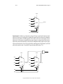
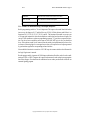
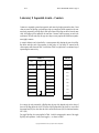
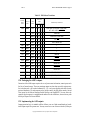
RESPONSE
What came back from the circuit (one or more values)
TEST VECTOR
The combination of stimulus and response
BEHAVIORAL MODEL
Software model of how the circuit should act
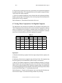
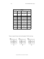
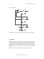
5.3.1 Guidance for automated testing of the 8-input multiplexer
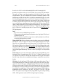
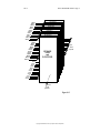
Build a programming model in C for an 8-input mux. The inputs to the model should be broken
into two sets: the Input set, I0..I7, and the Select set, S2..S0. Call this software model Mux; it is a
function of I0, I1, I2, I3, I4, I5, I6, I7, S2, S1, and S0. The function of the model is to accept a set
of 11 inputs and compute the value that a multiplexer would select based on that set of inputs. You
can use CASE statements or whatever programming construct "C" provides to compute this function. You do not have to model the mux in terms of AND, OR, NOT logic; in fact, you should not
do so. If the software model is well removed from the actual gate implementation you have a better chance of detecting logical or conceptual errors when you compare the real outputs generated
by your hardware against the corresponding software function.
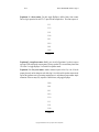
Now embed this function in a nested set of 11 FOR loops in a manner similar to that illustrated in
the Logic Engine users’s manual.
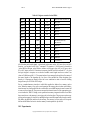
Run the program and let it generate all 2,048 input combinations. Read the result for each combination on LED1 or LED2. Compare the expected and measured results and print out appropriate
data if they disagree. You should now be confident of success when you submit this circuit for our
automatic grading program.
Copyright ©2000 Indiana University Computer Science Department