1
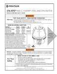
VIBRATION MEASURING SYSTEMS FOR DYNAMIC MACHINERY 1 INTRODUCTION The present document refers to the protection and monitoring of common dynamic machinery (pumps, fans, centrifuges, etc.), excepting turbo-machinery (turbines, compressors, etc.). The document focuses not only on the vibration measurement, but also on other relevant parameters for the correct assessing of dynamic machinery condition. 2 CLASSIFICATION OF MEASURING SYSTEMS Functionally speaking, the measuring systems can be classified as follows: a. Protection systems b. Monitoring systems c. Combined systems (protection and monitoring) The monitoring systems can also be classified as: Continuous monitoring systems - that continuously measures the monitored parameters (with the fixed mounted sensors on the machinery case). Discontinuous monitoring systems – these are usually portable instruments with a single transducer that can be used to perform a planed data collection of the important parameters (weekly, a monthly, etc.). Between protection systems and monitoring systems there are essential differences that will be next detailed. 3 PROTECTION SYSTEMS The main purpose of a protection system is to stop the machine anytime when the parameter values exceed a certain set limit, when the power supply fails or when the system itself fails. The protection systems may also have secondary functions, such as: the alert function, which offers an optical and/or acoustical signal when a set limit, lower than the shutdown limit, was exceeded; local display functions for the measured parameter; a function of long distance transmission (analog or digital) of information about the protection system condition and the measured parameters, as well. The Figure 1 shown below presents the block diagram of a protection system. 1 Sensor Transducer system RTDs Thermocouples Accelerometers Velocity Sensor leads Extension cables Accelerometer cables Machinery protection systems Signal processing Alarm/ Shutdown/ Integrity logic processing Monitor system Power supply(ies) Vibration Temperature Display indication Inputs/ Outputs Protective relays Figure 1 A protection system may consist of a single transducer (mono-channel protection system) or many transducers (multi-channel power system). The simplest protection systems are the vibration switches and they may be mechanic or electronic (Figure 2). Mechanical vibration switches provide basic, economical vibration protection by means of a simple and highly reliable “over center” snap action mass and spring mechanism. In the presence of sufficient vibration along the switch’s sensitive axis, the switch snaps from a stable “un-tripped” state to a stable “tripped” state, allowing automatic machinery shutdown or alarming when excessive vibration occurs. Figure 2 Once tripped, the switch must be returned to its un-tripped state via its local reset plunger or via voltage applied to its remote reset coil. A single set of SPDT relay contacts are provided as standard for connecting the switch to a machine control or annunciation circuit. Any protection system must have a response time less than 1 second. 2 The alarm response time should not be confused with the alarm delay time. The alarm response time is not programmable, but the alarm delay time is programmable .The alarm response time is the maximum time that can elapse in the system before detecting that a channel’s value has violated a set point. Once a set point violation occurs, the violation must be sustained for the alarm delay time before an alarm will be annunciated. This means that set point violations shorter than the alarm delay time will be detected, but not annunciated (output relay will not act). A special feature of the protection systems, named Set Point Multiplier Factor, is the capacity of temporary increasing the set alarm value for a short limited time, at the machinery startup. The Set Point Multiplier Factor is usually two or three times the set alarm value and the multiplication time is usually 10 to 20 seconds. At the machinery startup, a higher vibration limit may be temporary accepted, so only for vibration measurements is necessary to multiply the alarm limit. For each measured parameter, a protection system must provide two alarm levels: - A Warning Level, which it is just an annunciator that doesn’t lead to a radical decision to stop the machine. - A Danger Level, which leads to the triggering of a relay that consequently stops the machine. NOTE: The two alarm levels have different names and they are presented by API670 as follows: Warning – Alarm or Alert Danger - Shutdown or Danger Most of the protection systems have the retaining function (they memorize the alarms). Thus, even when the alarm condition disappears, the relay remains in the alarm position. To return the relay to the normal state, the system should be manually reset. The alarm relays can be: Normal energized, if the measured value remains under the alarm limit, the relay coil will be power supplied. Normal de-energized, if the measured value remains under the alarm limit, the relay coil will not be power supplied. The API670 standard recommends that Warning Relays to be normal deenergized and Danger Relays to be normal energized, because if the power supply is interrupted, the Danger Relays will become de-energized and they will determine a stop condition. Therefore, the machinery would remain unprotected if an accidental power loss occurs, which is undesirable. 3 As we already mention, any protection system should detect a transducer or a cable failure. Detection means: The triggering of an additional fail relay, eventually a light indicator; The direct triggering of the Danger Relay, in case of failure; If the failure is not detected by the protection system, then the machinery will work unprotected. To protect a machine, the vibration parameters should be: The Total Value, which normally means the vibration speed in mm/sec (according with ISO 10816 - "Mechanical vibration — Evaluation of machine vibration by measurements on non-rotating parts"). Bearing condition – A value that express the working state of bearings (gSE, SPM, Envelope, BC, etc.) The amplitude of fundamental (×1 RPM) or harmonics of it The Total Value in a well determined frequency range. The range recommended by the old ISO 7919 is 10 ÷ 1000 Hz. The most used transducers are the piezoelectric accelerometers placed onto the machinery case. Because the protection systems are expensive, people usually use only one transducer located on each bearing. Sometimes, a protection system with a single transducer is relevant and quite enough (for example, one transducer onto a fan bearing). Pay a special attention to the machinery located in potentially hazardous areas! In this case, the transducer that was located in a dangerous place must be separated from the protection system (located in the safe area), using some safety barriers. If the connection cable between transducer and electronic protection system is too long, then you should carefully select it. This means the cable should be screened and properly grounded, to avoid any electromagnetic interference. See below, in Figure 3, the connection diagram of a measuring channel to an accelerometer placed into a hazardous area. 4 Figure 3 If the equipment is located into a safe area, then protection barriers are useless. To measure temperature, into the combined protection systems, a RTD thermal resistance is usually located closer to the bearing. The RTD thermal resistance can be connected with two wires (for small distances between transducer and electronic protection system) or with three wires (to compensate the ohm resistance of the connection cable). Other facilities of protection systems are: Data transmission to a monitoring system (analog or digital); The possibility of measuring the signal from the transducer using an external system (such as a portable Spectra Analyzer); In this case, the output signal will have to be protected, so that any short-circuit 5 or any abnormal use of this signal does not affect the protection function. In conclusion, all the machinery protection systems must meet a number of special conditions: High reliability system; Short response time (less than 1 second); The system must protect the machine by stopping it, both from an accidental loss of voltage, but also from any self-failure or any cable connection failure. Alarm system must be latching type; this means it must memorize an alarm condition until it is manually reset; Protection system must have the facility of multiplication of Danger Value (eventually of Warning Value) during machinery startup. The relay which produces machinery shutdown must be normal energized; If the protection system is communicating either analogue or digital with a monitoring system, then no monitoring system malfunction should affect the functionality of the protection system. An external device (Spectra Analyzer) connected to the protection system should not interfere or affect anyhow its proper functionality. The use of common computers, PC type, in the protection system scheme (to switch the alarm relays) is not accepted! They can only be used in the monitoring system, which is outside of the protection system. The main conclusion is that the protection system must operate properly, unaffected by the monitoring system (if exists). This way, will be avoided any accidental stop, which is not the consequence of exceeding the alarm limits. 4 LOW-COST PROTECTION SYSTEM (EXAMPLE) A low cost protection system can be designed using CX-RLY-C Module. The system uses loop-powered CTC (LP250 Series) accelerometers, having the 4÷20 mA dc output. The output current represents the sensor zero-level (4 mA) and its full-scale output (20 mA). Only two wires are required to send the current signal and to ensure the power supply of the sensor. A loop supply voltage is used to power the remote sensor. The remote sensor regulates the loop current, so that the loop current represents the value of the parameter being measured by the sensor. A series resistor RL at the loop power supply converts this current to a voltage that can be used by the process monitor/controller to record the parameter being measured. The range, type, and units of the measurements are fixed and must be established when ordering the sensor. 6 Example: LP200 Series 4÷20 mA Velocity Sensors Loop Power Sensor, Velocity, 4÷20 mA Output for 0÷10 mm/sec rms. A single CX-RLY unit can be used to receive the vibration measurements from 2÷4 field transducers. See the typical wiring diagram in Figure 4 . In the wiring diagram, shown below, the +24 V power supply is considered to be external. To transform the transducers signal into voltage, two 250 Ω (0.1%) resistors are used. The output signal of 4 to 20 mA will be transformed in a 1÷5 V voltage range, suitable for CX-RLY-C Module. Because the input 3 and 4 are unused, the I-06 and I-07 are connected to +24 V. A single relay is used, so the RLY1 must be correctly mapped to both CH1 and CH2 inputs. Remember that the normal position of the relay contact can be NO or NC, depending of the settings. To fulfill protection system requirement the relay must be set to be CLOSE. A key-switch can be mounted between the I-02 terminal and +24 V. When the switch is closed, the relay will be placed onto the close position (nonalarm). If the I-01 terminal is temporary connected to +24 V exactly with the startup time, the alarm level will be doubled for 10 seconds. Only a pulse is required (a transition from the unconnected status to the +24 V status of the I-01 input). That’s how the machine will be still protected during startup, to avoid excessive vibrations that may damage it. A free relay contact from the electrical sub-station is required (an auxiliary contact of the machine start relay). For more details, see CX-RLY-C "User Manual". 7 Figure 4 The above diagram has two major disadvantages: Due to transducers’ type, dynamic signal (direct vibration for analysis) is not available. A remote indicator or the connection with an external SCADA system is not recommended. If the 4÷20 mA will be also connected to a SCADA input, the efficiency of the protection will be lost (any failure in the connection wire to the SCADA system will generate a false signal to CX-RLY-C module). A better protection system requires a supplementary device: a vibration converter. In the scheme below (Figure 5) is shown a protection system with two CTC SC200 series of vibration converter. 8 The SC200 converters accept direct standard accelerometer connections. The SC200 module has the following functions: transforms the accelerometer signal into velocity signal (by applying additionally HP and LP filters); transforms the velocity signal into a 4÷20 mA dc signal for the external remote indicators or for the acquisition systems (SCADA); transforms the velocity signal into a 0÷5 V dc signal to be directly connected to the CX-RLY-C module; ensures a buffered dynamic signal to a BNC connector (or to be used for an analyzer temporary connection, or to connect the dynamic signal to an external continuous monitoring system). Figure 5 For a detailed wiring diagram, download the SC200 User Manual from ctconline.com. NOTE: CX-RLY-C can also be connected to a temperature sensor with 4÷20 mA output. Using more CX-RLY-C modules, a combined vibration temperature protection system can be designed in the same way. 9 5 MONITORING SYSTEMS The purpose of machinery monitoring systems is to indicate/ to register the measured parameters. The main differences between monitoring and protection systems are: Monitoring systems allow a longer response time, including the measuring of parameters by channel multiplexing. Monitoring systems can be used for data processing, displaying and storing, including personal computer data. Monitoring systems cannot be used to stop a machine in alarm condition, but they can provide relevant data about the alarm condition of measured parameters. People often make confusion between these two systems, just because there are many instruments available on the market that meet both functions: protection and display/register. Protection system Figure 6 – Protection system Monitoring system Figure 7 – Monitoring system The response time of a monitoring system can be up to 20÷30 seconds. Usually, the monitoring systems are multichannel devices. The parameters can also be collected by channel multiplexing. The vibration monitoring systems were used almost exclusively in the past for critical or very expensive machinery. Nowadays, the monitoring systems are 10 used increasingly more often for common equipments, as well. A relevant example in this sense is the monitoring of machinery difficult to be accessed or placed in hazardous areas, where manual measurement involves a risk factor. Now, there are two different trends of using the vibration monitoring: to add vibration measurements (Total Value) on the list of monitored parameters of the plant (SCADA Systems, DCS, etc.), by using the wellknown loop powered 4÷20 mA sensors or to use independent monitoring systems, able to display more parameters than only Total Value, like vibration spectra, envelope, time waveform orbits or other relevant graphs. These systems can transfer by demand, even planned or only in alarm condition, information to a database, in order to establish the monitored machinery condition. In the first case, the number of relevant information is limited and the user can only compare the measured Total Value with a preset alarm limit. In the second case, the information provided by the independent monitoring system is helpful and relevant to accomplish a complex analysis and diagnose of machinery. NOTE: In a combined Machinery Protection (MPS) and Monitoring System (CMS), condition monitoring functionality is fed by machinery protection circuit, not vice-versa. Communications from MPS to CMS utilize completely separate busses and networks .Thus, the MPS is not compromised or impeded in any way by the CMS. Documentation Feedback Any suggestions and comments for improving this Application Notes should be e-mailed at [email protected] MaintTech Sweden uses feedback for continuous improvement of our documentation and for future MaintTech products. We request comments be specific and include the product name and version. We cannot provide personal responses to every message received, but please be assured that all feedback will be given careful consideration for future improvements to the MaintTech documentation or software. Technical Support Contact Details For any problem regarding this application, feel free to contact our support team at: [email protected] To know more about us, visit the following website: http://www.mainttech.se/ 11