1
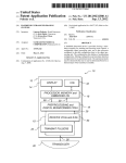
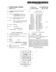
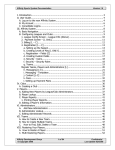
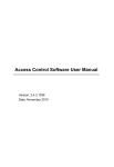
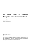
FPR-207 Fingerprint Reader
User Manual
Technological innovation originating from your desire !
Contents
Foreword …………………………………………………………………………………… 1
Chapter I : Product Introduction ………………………………………………………2
I. Brief introduction …………………………………………………………………………2
II. Construction ………………………………………………………………………………2
III. User authentication and signal characteristics ………………………………………3
IV. Functions …………………………………………………………………………………3
V. Performance indicators …………………………………………………………………4
VI. Packaging list ……………………………………………………………………………4
VII. Interfaces ………………………………………………………………………………5
VIII. Installation procedures ………………………………………………………………5
IX. Assembling diagram ……………………………………………………………………6
X. Notice on use of fingerprint registration ………………………………………………7
Chapter II : Setting ………………………………………………………………………… 8
[Short list of menu options] …………………………………………………………………8
[Description of menu options] ……………………………………………………………9
I. Start ………………………………………………………………………………………9
II. Standby image …………………………………………………………………………9
III. Fingerprint user management …………………………………………………………9
3.1 Register user & administrators (Enroll) …………………………………………………9
3.2 Delete user & administrators (Delete) …………………………………………………10
3.3 Browse user (Browse) …………………………………………………………………10
3.4 Clear user (Clear) ………………………………………………………………………11
IV. Card management ……………………………………………………………………11
4.1 Register card user ………………………………………………………………………11
4.2 Delete ID card (precaution) ……………………………………………………………11
4.3 Browse ID card …………………………………………………………………………11
4.4.1 Tamper (frequency of anti-tamper) ………………………………………………………13
4.4.2 Buzzer input setting (BUZ IN) …………………………………………………………13
4.5 Alarm ID setting (ALM ID) …………………………………………………………13
4 .6 Se tti ng of fi nge rp rin t collec tio n mode (CP MOD ) ……………………………… 13
V. Frequently used interface ……………………………………………………………14
User Manual of FPR-207 Fingerprint Reader
Foreword
Respected user: Thank you for choosing our product. Before installing and using the product, please read this
manual and the enclosed CD-ROM carefully and understand the basic construction, performance, function, and
basic knowledge about its installation, use, maintenance and system management. For inquiry, service, and
technical support, please contact the dealer for quick response.
Statement and notice
Nobody shall disassemble or copy the design of the device (including parts and components, circuit function,
and construction) without prior written authorization of our company.
Do not install and use the product in any area with inflammable or explosive substances and any sensitive areas
that may cause danger to electronic (electrical) devices! Please determine a correct location for installation and
install the power controller (higher than DC12V/2A) and prepare for connecting wires for the lock.
Do not use the device in any places with luminous intensity over 2000 Lux, direct sunshine exposure, rain,
vibration, and oscillation, with acidic gas or gas corrosive to metals, with the temperature lower than -10ºC or
higher than +55ºC, with the humidity less than 20% or over 90%, etc.
The application system does not contain any software and copyrights of Microsoft and other software and
copyrights that require authorization or licensed use. User shall understand and acknowledge: user may be required
to purchase or supplement the expenses of the copyright licensing or use of the software when applying the product
with system software about which no copyright has been granted or which is not yet authorized to use by the
copyright owner.
The product provider is not responsible for any losses because of improper use of the product (including
software and peripheral accessories).
Regular control and maintenance by designated personnel will further bring into play the reliability and
superiority of our product.
The user manual may be supplied with some mistakes in editing, typesetting and printing. The company reserves
the right to change any contents and parameters of this manual without further notice because of changes in
construction and technological upgrade. Please contact your dealer for any further inquiries.
Statement about human rights and privacy:
1. The civil-purpose fingerprint identification device only collects and saves feature points (numerical value) of
fingerprint other than fingerprint image, so this does not relate to reservation of privacy. The fingerprint image
shown by the software is collected on site and only for the purpose of observing fingerprint quality.
2. As an equipment provider, we are not responsible for any consequence as a result of use our equipment, directly
or indirectly.
3. If you should have any disputes about our equipment’s relationship with human rights or privacy or any other
issues, please contact your employer or provider directly.
-1-
User Manual of FPR-207 Fingerprint Reader
Chapter I Product Introduction
I. Brief introduction
Nowadays, in light of high technology, intelligent information processing has become a most effective way for
improving efficiency, standardizing administration and carrying out accurate identification, especially in the field
of enterprise and public undertaking management. Door access control system (entry and exit control and
management system) is now an important component of security protection system. In developed nations, door
access system is making progress rapidly with a growth rate much higher than that of other security protection
products. The fundamental reason for fingerprint door access system to overcome other door access systems is that
it changes the passive protection mode of previous products that “identifies article other than people”, preventing
unauthorized personnel from entering regular channels.
FPR-207 fingerprint and inductive card reader is capable of outputting Wiegand 26/34 standard signal and
supports online communication by RS485. It is compatible to traditional and new door access control system
readers so as to upgrade the system to fingerprint and inductive card door access control system. This product is
characteristic of universality, reliability, innovative design, pleasant configuration, and the ease of installation.
The product belongs to the fingerprint identification device with the widest application in the field of door
access system. It adopts wall-hanging installation and features the ease of operation, innovative structural design,
and pleasing exterior design. The product is suitable for modern application environment. To upgrade the system to
the all-purpose door access control system, will add to the satisfactory building environment.
II. Construction
The human-device interface consists of display, keys, fingerprint scanner and beeper. Their functions are
described as follows:
1. Display: Indicating user’s authentication status and result, management menu, etc.
2. Keys: 12 keys altogether, including numerical keys 0~9, * key and # key. Numerical keys are used for typing
ID and other information as well as selection of menu options. Press * key to cancel the operation or return. Press #
key to confirm operation. 0 and 9 keys also function to turn up and down pages in menu operation.
3. Fingerprint scanner: Collection and comparison for user fingerprints. The lit red indicator of fingerprint
scanner indicates it is waiting for the user to put the finger on it. The red indicator of the scanner is constantly lit
under automatic collection mode (refer to the collection mode setting in the management menu).
4. Buzzer: Key hinting and operating status and result hinting. One short sound indicates successful key
operation or authentication; one long sound indicates successful operation; three sounds indicate authentication or
-2-
User Manual of FPR-207 Fingerprint Reader
operation failure. Two sounds indicate successful previous operation and the start of second stage operation. This
hints the user to press the finger again during the process of fingerprint registration.
III. User authentication and signal characteristics
The user authentication consists of three types: fingerprint authentication, inductive card authentication and
conductive card + fingerprint indication.
1. Fingerprint authentication: Under automatic collection mode, put a finger on the fingerprint scanner so as to
start the 1:N type of authentication. Wiegand signal consisting of the user ID will be outputted upon fingerprint
authentication (see the format of Wiegand output as follows).
2. Inductive card authentication: Use the card in the keyboard zone under standby status and the card’s Wiegand
number will be output.
3. ID card + fingerprint authentication: Use the card and then fingerprint when the authentication logic is set to
ID + fingerprint. When “Card + fingerprint” function is in use, set the scanner first to the mode of “Card +
fingerprint”. Use the card when typing FPID during registration. The card number inputted is the FPID.
4. The format of Wiegand includes 26-digit and 34-digit. The inductive card authentication outputs directly the
Wiegand card number of the current ID card, of which the format is fully compatible to that of other Wiegand
inductive card readers. This facilitates mixed use or upgrade of traditional and new door access systems.
IV. Functions
Professional use: US dual-core Blackfin and SM&MTA door access fingerprint identification technology;
scratch-resistant, static-resistant diamond crystal high-resolution fingerprint scanner.
Extra-large capacity: Registration of 5 administrators, 3,500 users (3,500 fingerprints). Each user may register
more than one fingerprint. The number of fingerprints for each user is controlled by administrator.
ID card direct output: ID card signal is directly converted to Wiegand signal for output when inductive card is
used. It is fully compatible to the door access system.
High level of security: Grade 9 for fingerprint identification security. FRR≤0.0001% false rate.
Identification speed: High speed of identification: fingerprint identification≤1s, inductive card identification≤
0.5s.
Authentication: Three modes of authentication include fingerprint, inductive card, and inductive card +
fingerprint, facilitating system upgrade of existing and new door access control.
Output format: Standard Wiegand26 or Wiegand34 output format, compatible to door access controllers made
in China and abroad; similarity of the mode of connection by the scanner to ordinary inductive card reader, with
full compatibility and easy installation.
Human-machine interface: Human-machine interface with voice function and character LCD display, visual
and convenient.
Tamper alarm: Tamper alarm function, on-site alarm and level output, provision of external alarm or
connection to 110 network.
Duress alarm: Designated alarm ID could be outputted in case of fingerprint unlocking during duress alarm.
Confinement against wrong input: Options for 0~255 times against tryout; 180s confinement status after
tryouts.
Off-line operation: Mode of fingerprint identification access for administrator based on disconnection to PC,
supporting direct registration, modification, deletion, setting etc. on the local frame.
Network communication: 485 online communication, reading and writing with dedicated software in the
attached CD-ROM for fingerprint scanner, backup, copying of fingerprint information, setting of relevant
parameters, editing of user information in the software.
-3-
User Manual of FPR-207 Fingerprint Reader
V. Performance indicators
Item
Technical parameters
Fingerprint ID technology
US BlackfinTM Dual-core and SM&MTA technology, optical design,
high scratch resistance, static resistance
FRR
≤0.01%
FAR
≤0.0001%
Registered number of fingerprint
3,500 fingerprints (1 ID supports more than one fingerprint; the unit
may also be expanded to 6,000~16,000 fingerprints upon customer
request)
Max. capacity of registration
3,500 fingerprints, direct inductive card operationWiegand output,
based on door access Control system configuration
Mode of analysis
Speed
Type of inductive card
1:N, 1:1
≤1 second
EM card or compatible ID card
Reading distance
≥5cm
Reading speed
≤0.5s
Output
Output format
Alarm function
Confinement against wrong input
Direct output after use of inductive card, output after fingerprint
authentication, output of inductive card + fingerprint.
Wiegand 26/34
Tamper alarm, low level output
Optional number of tryouts of 0~255 times, 180s confinement status
after tryouts
Communication
Display
RS-485, supporting 255 frames online maximum
640 matrix, 2×8 dots character matrix LCD display
Ambient temperature
-10°C~+55°C
Ambient humidity
20%~80%RH
External power supply/power
Volume / weight
DC10~15V/≤3W
143mm×67mm×50mm / 255g
VI. Packaging list
No.
Equipment
Unit
Quantity
Set
1
Piece
1
Packaget
1
1
Fingerprint reader
2
CD-ROM of application management software
3
Dedicated connecting wire
4
Instruction manual (electronic form, in the CD-ROM)
Piece
1
5
Silica gel fillet
Piece
1
6
Drywall screw + Plastic expansion screw
Pair
4
7
Flat-head screw
Piece
3
8
Connecting accessories
Piece
Several
9
Bottom mounting cover plate
Piece
1
10
Certificate of conformity and quality assurance
Copy
1
Please check completion of above accessories. If there exists any discrepancy, please contact your distributor
immediately.
-4-
User Manual of FPR-207 Fingerprint Reader
VII. Interfaces
The hardware interfaces including power input, RS485 communication port, relay port, etc. The feet are
defined in the following table on the rear side of the fingerprint reader from left to right:
Socket foot position
Item
Color/position
1
+12V (DC10~12V input)
2
GND (power supply grounding)
Black
3
BUZ_IN (buzzer signal input, low level buzzer sound)
Green
4
WG_INT (Wiegand delay output, low level indicating that Wiegand
signal is being outputted)
White
5
WG_D0 (Wiegand signal D0)
Brown
6
WG_D1 (Wiegand signal D1)
Yellow
7
485B- (485 communication signal, negative)
Purple
8
485A+ (485 communication signal, positive)
White
9
GND (numerical, same to power supply grounding)
Black
10
NC (reserved, normally close contact switch of alarm output relay)
Blue
11
NO (reserved, normally open contact switch of alarm output relay)
Gray
12
COM (reserved) (common contact switch of alarm output relay)
JP2
OFF (close field alarm); NO (open field alarm)
KEY
Red
Temper switch: loosen for alarm, press to cancel.
Orange
Toggle switch
Pressure switch
VIII. Installation procedures
1. Locate 4 mounting holes with mounting hanging plate at a proper height (about 130cm above ground) and
then dismount the hanging plate. Drill the holes with Ö6 chopping bit and then mount the plastic expansion screws
attached in the accessories until the screw heads are even with the wall surface. Connect all necessary wires and
then mount the mounting hanging plate. Finally, fasten with drywall screws.
2. Insert the connecting plug to the mainframe socket. Connect to power supply to test the various functions.
Then, press the mainframe on the mounting hanging plate downward and fasten with attached 3×6 flat-head screw.
Finally, cover with the attached lower sealing cover plate and insert silica gel joint strip.
Installation dimensions of FPR-207 door reader
-5-
User Manual of FPR-207 Fingerprint Reader
8-3: Screw mounting drawing
8-1: Hanging plate
8-2: Installation
8-4: Lower sealing plate
8-5: Installation of
silica gel strip
IX. Assembling diagram
FPR-207 fingerprint scanner is compatible to all kinds of door access controllers made in China abroad. The
interfaces with controller include WG26 and WG34 (WG26 or WG34 is optional on the scanner). 485 interface
communication is supported for online operation of multiple fingerprint scanners. The addition of user, deletion,
copying of user data, etc. for different scanners are supported by the management tools. The installation diagram
for networking of the devices is shown as follows:
Figure 9-1: Online communication diagram of FPR-207 fingerprint reader
-6-
User Manual of FPR-207 Fingerprint Reader
X. Notice on use of fingerprint registration
1. To register a fingerprint, put a finger on the center of the prism; do no move freely to any direction.
2. Put a finger on the device with force, just like pressing a door bell.
3. Moist the finger properly: If the weather is dry, the user may breathe on the finger or wipe the finger on his
forehead.
4. Excessive water on finger or sweating may conceal lines on fingerprint, failing the scanning. Please wipe the
finger to dry properly.
5. Severe desquamation of finger may affect use of the system. Please change a finger without desquamation and
then register again.
6. It may be difficult for a user with a finger to register, of which the fingerprint is too closely distributed that
almost no fingerprint could be identified. In this circumstance, user may register a few fingerprints with relatively
larger fingers with force.
7. The fingerprint cannot be read accurately if there is any dirt or other foreign matters on the prism surface of
the fingerprint scanner. Clean the prism surface of fingerprint scanner regularly so as to keep the system operating
under optimum status.
8. In particular, fingerprint scanning may fail if the finger is dirty seriously. Therefore, please keep the finger
clean as possible during registration and use of the system.
The correct method of registering a fingerprint is shown in following Figure 10-1:
10-1: Correct posture to press a fingerprint
The incorrect method of registering a fingerprint is shown in following Figures 10-2~10-5:
10-2: Finger not placed evenly
10-4: Finger too oblique
10-3: Horizontal direction departing from the center
10-5: Vertical direction departing from the center
-7-
User Manual of FPR-207 Fingerprint Reader
Chapter II Setting
[Short list of menu options]
Power on. Hold * key for 3s in standby interface (authenticate administrator fingerprint in Verity Master
interface if any administrator is registered) and then enter management menu. “0~9” are for setting, * key is for
return, and # key is for confirmation.
1. Finger (fingerprint)
Notice:ID number of 1~5 will be deemed as administrators by the system in default.
1. Enroll
FP:_ (input ID)
1. Normal (normal finger)
2. Alarm (alarm finger)
2. Delete
FP:_ (input ID)
3. Browse
C:xxxxx (number of fingerprints)
M:xxxxx (capacity of fingerprints)
FP:xxxxxxxxxx (browse fingerprint: use UP and DOWN keys to change page and press
Confirm to confirm operation)
1. Enroll
FP:xxxxxxxxxx_ (input ID)
1. Normal (normal finger)
2. Alarm (alarm finger)
2. Delete
FP:xxxxxxxxxx_ (input ID)
4. Clear (clear)
DEL ALL Fingers?
2. Config (configure)
1. Number (device number)
Number:
xxx (1~255, default: 001; press Confirm to modify)
2. Logic (authenticating logic)
1. ID/FP (ID card or fingerprint)
2. ID+FP (ID card plus fingerprint)
3.WG FMT (Wiegand format)
1.26-bit (Wiegand 26)
2.34-bit (Wiegand 34)
4.1 Tamper (frequency of anti-tamper)
(Some model does not supply menu but the line function provides this.)
Tamper:
xxx (0~255, default: 0; press Enter to modify)
4.2 BUZ IN (buzzer input)
(Some model does not supply menu but the line function provides this.)
1.No
2.Yes
-8-
User Manual of FPR-207 Fingerprint Reader
5. ALM ID (alarm ID)
ID: xxxxxxxxxx (press confirm to change)
6.CP MOD (fingerprint collection mode)
1. Normal (normal)
2. Auto (automatic collection)
[Description of menu options]
I. Start
Connect DC12V±2V/2A power supply that meets safety requirements to the power line of the device. The
startup mode is entered.
SelfTest
…
II. Standby image
The standby status is entered after 1 second when the power supply is connected.
Welcome!
III. Fingerprint user management
Hold * key for 3s to enter menu management (the administrator must use fingerprint if any administrator is
registered). The main function menu consists of four options: 1. Finger (fingerprint user management); 2. Config
(system configuration).
1.Finger
2.Config
(设置)
3.1 Register user (Finger)
Notice:ID number of 1~5 will be deemed as administrators by the system in default.
Enter the subdirectory of the menu. Select 1. Finger. Press # key to enter fingerprint user management, which
contains: 1. Enroll (register user); 2. Delete (delete user); 3. Browse (browse user); 4. Clear (clear user).
1.Enroll
2.Delete
Select 1. Enroll. Press # key to enter the menu of user/administrator fingerprint registration.
FP:_
Enter user ID. The administrator IDs is 1~5. Users with ID number of 1~5 will be deemed as administrators by
the system in default (when any administrator is registered, it is required to hold * key for 3s and the administrator
must use the fingerprint to enter the menu).
Note: Please understand the minimum ID number of the door access controller connected when setting up user
ID. If the minimum allowable user ID is 100 for a certain door access controller, the user ID registered at the
scanner shall begin from 101. For example, enter user ID 101 and then press #.
To register a user with the authentication of “ID card + fingerprint”, the user shall first set the device to
the mode “ID+FP”. See Clause 4.2 authenticating logic (Logic) for detail. After setting to the mode “ID+FP”,
-9-
User Manual of FPR-207 Fingerprint Reader
use ID card in the interface of entering ID number for registered user. At this moment, the ID card number
is the ID of the current fingerprint user. Press #.
1.Normal
2.Alarm
Select 1. Normal. Press # to register “Normal
finger”.
2.Master
First
Capture.
According to above operating procedures, put the desired finger evenly on the fingerprint scanner. The scanner
indicator flickers for 2 times. Two short sounds “dip, dip” and one long sound “dip~” indicate the fingerprint is
registered successfully and then the system returns to user registration interface automatically.
To register more than one fingerprints for one user ID, a user shall press # again to continue registration. Put the
desired finger on fingerprint scanner for data collection. The method of registration is same to registration for the
first finger. The user shall repeat this operation for registration of several fingerprints under a same ID. Press # and
then change a finger for registration. The number of fingerprints to register under a same ID is not limited and the
user has the free choice for registration. To delete a user with several fingerprints registered, it is required to delete
the ID only and then all the fingerprints’ data under this ID will be deleted.
Note: 1. Normal means “Normal finger”. To register a fingerprint for normal unlocking, user needs only to select
1. Normal for registration. 2. Alarm means “Alarm finger” (duress alarm fingerprint). When an alarm fingerprint is
registered, user may press the alarm finger in an emergency condition and the scanner unlocks the door normally
and a group of present alarm ID numbers is transmitted to door access controller. The signal is also transmitted to
the management software for alarming and hinting the management personnel. Please refer to the following item
4.5 on alarm ID setting for the details of setting up alarm ID.
3.2 Delete user (Delete)
Notice:ID number of 1~5 will be deemed as administrators by the system in default.
Select 2. Delete. Press # key and the screen hints as follows to input the user ID to delete.
FP:
Press # to delete the user (precaution!). Press * to return.
Delete
ok
3.3 Browse user (Browse)
Select 3. Browse. Press # key and the screen hints as follows:
C:6
M :3584
C:xxxxx (number of fingerprints)
M:xxxxx (capacity of fingerprints)
Press # to browse registered user IDs, shown as follows:
FP:00000
00101
- 10 -
User Manual of FPR-207 Fingerprint Reader
FP:xxxxxxxxxx, browse fingerprint users; press “9 0” to turn pages.
If FP:xxxxxxxxxx S is displayed, S indicates the beginning figure and E indicates the ending figure.
3.4 Clear user (Clear)
Select 4. Clear. Press # key and the screen hints as follows:
DEL ALL
Fingers?
Press # to clear all the users. Press * to return without clearing.
IV. System configuration
Select 4. Config in main menu. Press # and six options are shown: 1. Number (device number), 2 Logic
(authenticating logic), 3. WG FMT (Wiegand format), 4. Temper (sensor delay) or 4. BUZ IN (buzzer input), 5.
ALM ID (alarm ID), 6.CP MOD (fingerprint collection mode).
4.1 Setting of device number (Number)
Select 1. Number. Press # key and the screen hints as follows:
Number :
001
Press # to change the door reader device number. The scope is: 001~255. Type the device number and press #
to confirm. User must set different device numbers and the default is 001 when door reader devices are in
networking by RS485.
4.2 Setting of authenticating logic (Logic)
Select 2. Logic. Press # key and the screen hints as follows:
1.ID/FP
2.ID+FP
Select 1. ID/FP. Press # to confirm. The door reader device may operate under ID card mode or fingerprint mode.
Select 2.ID+FP. Press # to confirm. The door reader device may only operate under ID card + fingerprint mode.
Use ID card under ID card + fingerprint mode first. Then, scan the finger corresponding to the ID card to unlock
the door.
Card +
Finger
ID Card
First
ID card + fingerprint authentication
ID card authentication + fingerprint
4.3. Wiegand format setting (WG FMT)
Select 3. WG FMT. Press # key and the screen hints as follows:
1. 26-bit
2. 34-bit
Select 1.26-bit to set the scanner to work 2.Master
under Wiegand 26 mode.
Select 2.34-bit to set the scanner to work under Wiegand 34 mode.
Note: Explanation of standard WG26/WG34 definitions: the maximum user ID is 16777216 under WG26 format
and the maximum user ID is 4294967296 under WG34 format. Please pay attention when the device is used with
door access controller.
- 11 -
User Manual of FPR-207 Fingerprint Reader
4.4.1 Tamper (frequency of anti-tamper) (Some models do not supply this menu.)
Tamper:
xxx (0~255, default: 0; press Enter to modify)
Tamper
xxx
2.Master
The purpose is to prevent against illegal tryout
and comparison. When illegal tryout reaches the set frequency
(0~255; press Enter to set; it is suggested to set to 20) in the device, the device will suspend for 180s. In this
period the screen shows timing. All the operations with the panel will not be available except for the exit button
function.
4.4.2 Buzzer input setting (BUZ IN)
(Some model does not supply menu but the line function provides this.)
Enter the subdirectory and select 4. BUZ IN, shown as follows:
Select 1. No which means no buzzer input.
Select 2. Yes which means buzzer input.
1. NO
2. Yes
2.Master
4.5 Alarm ID setting (ALM ID)
Select 5. ALM ID for alarm ID setting, shown as follows:
ID:00000
00110
Enter the user ID for alarm purpose (the alarm ID is user-defined; an ID cannot be used as regular user ID when
it is selected as an alarm ID). Press # to confirm. The administrator IDs is 1~5. Users with ID number of 1~5 will
be deemed as administrators by the system in default (when any administrator is registered, it is required to hold *
key for 3s and the administrator must use the fingerprint to enter the menu).
For example, set the alarm ID of a scanner to “110” and press # to confirm. In standby status of the scanner, the
user presses the registered “alarm fingerprint” (see aforesaid Clause 3.1 on user registration for the procedure of
registering an alarm finger). The scanner outputs the ID “110” to door access controller, which then sends the
signal to management software. The management software has defined the ID “110” as the alarm user. The
management personnel of the surveillance software, at this moment, could deal with the alarm event immediately.
Case of alarm finger application: When fingerprint scanner is in use in some important circumstances (vault,
financial room, warehouse, etc.) and a user is threatened by someone to put the finger on the scanner to open a door,
the user could use the registered “alarm finger”. Then, the door will open normally and the scanner outputs
automatically preset alarm ID “110” to the management software. The management personnel is notified on
threatening of door unlocking and then take immediate measures.
Note: Please understand the minimum ID number of the door access controller connected when setting up user
ID. If the minimum allowable user ID is 100 for a certain door access controller, the user ID registered at the
scanner shall begin from 101.
4.6 Setting of fingerprint collection mode (CP MOD)
Select 6. CP MOD. Press # and the screen hints as follows. Two modes are available: 1. Normal (normal mode),
2. Auto (automatic mode).
- 12 -
User Manual of FPR-207 Fingerprint Reader
1. Normal
2. Auto
2.Master
Under normal mode, the reader’s indicator light
is off for standby status. To analyze fingerprint, press # key and
the indicator is lit. Put a finger on the fingerprint scanner for analysis.
Under auto mode, the reader’s indicator light is lit for standby status. To analyze fingerprint, put a finger directly
on the scanner for analysis (it is recommended the device is used under auto mode for convenience of use).
V. Frequently used interface
Welcome !
Verify
Master
Standby interface
Administrator
authentication
ID: 0 0 0 9 5
9 6 8 8 8 OK
Card comparison passed
Invalid
Card
Invalid card
Broken
Alarm
Tamper alarm
Sensor
Close
Identify
Failed
Sensor closed
Identification failure
Card +
Finger
ID Card
First
ID card + fingerprint
authentication
- 13 -
ID card + fingerprint
authentication
Identify
Identification ready
Verify
Failed
Verification failure
Tamper
Lock: 180
180s anti-tamper
confinement