1
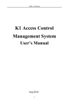
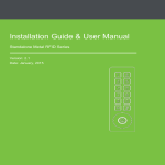
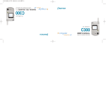
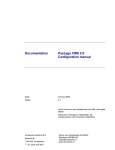
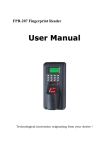
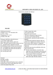
Dear Customer:
Thank you for purchasing our product, MF850 Fingerprint access control!
To fully enjoy the benefits of this product, please read instructions included in this
manual carefully.
Version: Ver 1.0 (Jan, 2010)
All images in this manual are for reference, and should be subject to the actual
product.
Because there might be print errors, inaccurate descriptions in this Manual, and the
Manual might be updated, this manual will be subject to change. In case any
modifications of this manual occur, the updated version will include these changes,
without any notice.
Guarantee on Human Rights and Privacy
We hereby guarantee that fingerprint access controls supplied by our Company only
acquire fingerprint minutiae and do not preserve fingerprint privacy. In addition, the
fingerprint minutiae cannot be restored to the original fingerprint images. Therefore,
your human rights will not be violated. Under no circumstances shall we, the provider
of the equipment, be liable to any direct or indirect consequences arising out of or in
connection with our equipment. In the event of any disputes with the user on human
right copying or privacy. Please communicate with your employer.
Fingerprint Access control User’s Manual
Table of Contents
Table of Contents
Chapter One Product Overview
1.1
System Overview ............................................................. - 3 1.2
Parameters ........................................................................ - 4 1.3
Hardware Installation ....................................................... - 6 1.4
Appearance Description ................................................... - 7 1.5
Interface Explanation ....................................................... - 8 1.6
Fingerprint Placement Guide ........................................... - 9 Chapter Two Basic Function
2.1
Keyboard ........................................................................ - 10 2.2
Menu .............................................................................. - 11 2.2.1 Menu structure ............................................................... - 11 Chapter Three Operation Flow
3.1
Initial Use ....................................................................... - 14 3.1.1 Hardware Installation ..................................................... - 14 3.1.2 User Registration ........................................................... - 14 3.1.1. Delete Registered Data .................................................. - 18 3.1.2. Settings Relating to Access Control ............................... - 19 3.1.5 Attendance/Access Control Operation ........................... - 22 3.1.6 Record Searching ........................................................... - 24 3.2
Daily Use ....................................................................... - 24 Chapter Four Management Operation
4.1
Enter Management Menu ............................................... - 24 4.2
Data Management .......................................................... - 24 4.3
Setting ............................................................................ - 25 4.4
Access Control Setting ................................................... - 30 4.5
System Information ........................................................ - 33 4.6
Shortcut Key Setting ...................................................... - 33 Chapter Five MF-10 Description
5.1
Product Overview .......................................................... - 35 5.2 Instruction for Connection of Access Control and MF-10- 35 -1-
Fingerprint Access control User’s Manual
5.3
MF-10 Operating Instruction ......................................... - 36 Technical Support
Appendix
-2-
Fingerprint Access control User’s Manual
Chapter One Product Overview
1.1 System Overview
A fingerprint Access control combines functions of access control and time and
attendance management. It provides safe access control function as well as convenient
time attendance management. A fingerprint access control management system
consists of a fingerprint access control terminal (hereinafter called access control),
electronic lock controller, electronic lock, door sensor, alarm bugle, button, door bell,
power, PC and access control management software.
The access control is responsible for user’s information registration and daily
identification of entry in and out. When used as access control, it allows the user to
open the door by pressing the registration finger, without using a key. When used for
both access control and time attendance, it allows that only registered fingerprints are
required for these purposes.
The access control system is designed to configure parameters, back up data of
the equipment, and download access record. It also conducts data statistics and
processing according to the time and attendance rules set forth by the administrator,
generates various statistical reports, and enquires in and out record logs. As a result, it
can fulfill the functions of access control, and time attendance.
The access control can operate in off-line mode, without being connected with
the management software. For an access control used without the management
software, functions of user validation period and real-time monitoring are not
available.
There are mainly two communication modes between the access control terminal
and access control management system, namely, RS485, TCP/IP.
The system configuration is shown in the following diagram:
-3-
Fingerprint Access control User’s Manual
Controlled
Lock Power
Electric Lock
Door Sensor
Access Control
Alarm
Bell
Push Button
Schematic for Installation of Access Control
TCP/IP、RS485
Outdoor
Indoor
1.2 Parameters
Description
MF850 fingerprint access control
Working voltage
12V
Static
working
current
Dynamic current
Relay
contact
current
250MA
3A 120VAC/28VDC
2.4’ TFT color screen
LCD
Operation
temperature
Dimension (mm)
Relative
150MA
operation
humidity
0℃-- +45℃
185 X 80 X 35
20%--60%
Fingerprint sampler
High-hardness optical fingerprint sampler
Keyboard
20 tact switch
Main board
Smart KM dual-core low-consumption
structure
Core algorithm
HAS 8.0
FRP
≤1%
-4-
Fingerprint Access control User’s Manual
FAR
≤0.0001%
Reaction time
≤1s
Working mode
Offline/ inline
Sensitivity
level
setting
1:N/1:1
Fingerprint-password-card, fingerprint +
Identification mode
password, fingerprint + card, card +
password, card + fingerprint + password
Capacity
of
fingerprint
Capacity
of
management record
Capacity of in and
out records
Communication
mode
1, 500
1,000
60, 000
RS485, TCP/IP
Language display
Simplified/ Traditional Chinese, English
Vocal instruction
Five parts of high quality voice
Name display
Long name display (in Chinese/ English)
Time group
30 groups
Time section
50 sections
Alarm
Alarm for removal prevention, alarm for
overtime opening, alarm for tamper
resistance, alarm for external input points
Fire
fighting
Available
blocking
Threatening alarm
Available
Exit button
Available
Wigand interface
Supports standard 26/34 input and output
Tamper resistance
Available
Real-time monitor
Available
Validity
Available
-5-
Fingerprint Access control User’s Manual
Extension module
ID / IC / HID
Bell ring function
20 groups of rings
Doorbell interface
Available
1.3 Hardware Installation
Installation Procedure
The access control is of mounting type. The steps for installation are as follows:
1) Positioning: Position four holes on appropriate wall according to iron board’s
holes.
2) Drilling: Drill four holes using screws (supplied with terminal)
3) Fixing iron board: Put an iron board on appropriate place of the drilling area.
And then fix the iron plate firmly by beating the screws.
4) Suspension: Hang up the terminal on the iron board (with the bottom 1.4m from
the ground).
5) Powering on: Connect the equipment as per the reference connection diagram,
and power on the equipment.
6) Connecting to the computer: The product may be connected to the computer
using RS485 or TCP/IP. Select a communication mode for the access control and
management computer. Then, set up communication parameters on the access control
(See Section 4.3). Connect the access control and computer with communication
cables. Then, install the management software on the management computer, and set
related communication parameters, which must be the same with the parameters on
the access control. (For operating modes, see the User’s Manual for Reference
Software).
Notices for Installation:
1) Environment: It is recommended that the access control be installed indoor. If
used outdoor, the equipment must be protected against strong rays and rains. It is also
recommended a sunshade and heat dissipation device be used in summer, and thermal
insulation facilities be used in winter.
2) If RS 485 communication cables are used, the cables must be double-core
shielded wire. Avoid using network cables. Do not connect the equipment to strong
power (220V). The maximum communication distance is 1100m. Additional repeaters
must be provided for communication distance greater than 800m, so as to ensure
communication reliability. For RS485 communications, it is recommended that Baud
-6-
Fingerprint Access control User’s Manual
rate be set to 19,200, because the communication reliability and transmission distance
increase when Baud rate reduces. But the transmission speed falls when the Baud rate
reduces.
3) Wiring for the exit button should not be too long, instead, it should be close to
the terminal as applicable.
4) The controlled lock power should be close to the terminal and electronic lock as
applicable.
5)
The relay can control the electronic lock directly and the maximum withstand
current is DC 30V/2A.
1.4 Appearance Description
-7-
Fingerprint Access control User’s Manual
1.5 Interface Explanation
(1) RJ45 communication interface (8P-2.54) definition
PIN
Definition
Description
7
RS485+
485+
8
RX485-
485-
(2) Access control interface 1 (12P interface on the left of the back) definition.
P
IN
Definit
Description
ion
1
BELL2
Doorbell interface 2
2
BELL1
Doorbell interface 1
3
P2
External signal input 2
4
P1
External signal input 1
5
GND
Power supply grounding
6
D1_IN
Wigand data 1 input
7
D0_IN
Wigand data 0 input
D1_O
Wigand data 1output
D0_O
Wigand data 0 output
8
UT
9
UT
-8-
Fingerprint Access control User’s Manual
1
GND
Power supply grounding
COM_
MF-10 interface
COM_
MF-10 interface
0
1
1
B
1
2
A
(3) Access control interface 2 (12P interface on the right of the back) definition.
1
+12V
Power supply (+12V)
2
GND
Power supply grounding
3
T_ALM_OUT
Output terminal of hidden alarm
control
4
T_ALM_IN
Input terminal of hidden alarm
control
5
ALM_OUT
Output terminal of exposed alarm
control
6
ALM_IN
Input terminal of exposed alarm
control
7
OPN_S
Door lock switch
8
OPN_K
Exit button
9
GND
Power supply grounding
10
NC
Normally closed terminal of lock
sensor
11
COM
Common terminal of lock sensor
12
NO
Normally open terminal of lock
sensor
1.6 Fingerprint Placement Guide
When installation of the terminal is completed, the fingerprint will be registered
first, which is followed by validating operation. The recommended finger for
registration is the forefinger and middle finger.
-9-
Fingerprint Access control User’s Manual
Correct
Too
perpendicul
ar
Too
deflective
Too oblique
Too low
Correct pressing manner: Correct finger placement method: Press with your finger on
the fingerprint gathering window. Make sure the fingerprint’s centre is aligned to the
centre of the gathering window as much as possible. Finger press method is shown as
the following figure.
Chapter Two
2.1
Basic Function
Keyboard
The configuration of the keyboard is shown in the following figure.
The function is described as follows:
ESC:To perform EXIT or CANCEL; OK: To confirm; MENU: To access menu
management; ▲ or ▼: Scroll-up/ down button for menu operation; 0…9: To input
numbers; F1-F4: Shortcut keys (The definition is given in Section 4.6)
- 10 -
Fingerprint Access control User’s Manual
Menu
For the access control, you
can use function keys and
numerical keys to perform
flexible menu selection, keyboard
input and various settings. The
level-1 menu includes three
categories: record management, setting and system information. Each
menu consists of different subordinate level-2 and level-3 menus to
perform corresponding operations.
2.2.1
Menu structure
2.2
The constitutions of the level 1 menu are:
1)
Data management: To register and delete the fingerprints, passwords and data on
inductive card for users or administrators, and all records, and to set safe value of
algorithm.
2)
Setting: To set system parameters for the terminal.
3)
Access control setting: To set parameters for the terminal.
4)
System information: To examine the information recorded in the terminal.
The structure of level 1 menu is shown in the figure above. Only a super
administrator is entitled to have access to ―Setting‖ and ―Terminal Setting‖ options in
the level 1 menu. An ordinary administrator is granted access to only a part of level 2
menu under ―Data management‖ (level 1 menu) and ―System information‖ of level 1
menu.
The structure of level 1, 2 and 3 menus are described as follows:
2.2.12.
Setting Menu
Select ―Data Management‖ using ▲/▼ in level 1 menu. Then press ―OK‖ to
access the level-2 menu, which has totally 5 items. Move the cursor using ▲/▼ to
select desired option among menus of the same level. Press OK to access the
sub-menus of the selected menu. Press ESC to return to the higher-level menu.
Level-4 menu is contained in the ―Super Administrator‖ and ―Registered
Administrator‖, which are level 3 menus. The content of the menu is identical with the
level-3 menu under ―User Registration‖.
The structure is shown below:
- 11 -
Fingerprint Access control User’s Manual
Password
User
Level 1 menu
Level 3 menu
Level 2 menu
Note: The ID cards are not included in the standard functions, and must be used with
an external reading head.
Only the super administrator is entitled to access the following items under the
level 3 menu: ―super administrator‖, ―registered administrator‖, ―1:1 safety setting",
―1:N safety setting‖, and ―delete all records‖. In addition, when executing ―Delete
registered data‖, the super administrator can only delete the user’s registered data and
data of an administrator belonging to the same level.
2.2.12.
Setting Menu
In the level 1 menu, when the cursor is at ―Setting‖, click ―OK‖ to enter the level
2 menu. This menu has three setting items, and there are corresponding sub-items
(level 3 menus) under the level 2 menu. The structure is shown in the following
figure.
- 12 -
Fingerprint Access control User’s Manual
Total No. of administrators
Language
Time setting
Time format
Vocal language
System Setting
Sensitivity adjustment
Restore factor setting
Machine No.
Baud rate
Setting
Port No.
Communication
password
Communication
setting
IP address
Level 1 menu
Subnet mask
Default gateway
Outgoing and incoming
records alert
Management records
alert
Record setting
Level 2 menu
Level 3 menu
Note: Only the super administrator is entitled to enter the following items under the
level 2 menus: ―system setting‖, ―communication setting‖ and ―record setting‖.
2.2.13.
Access Control Setting Menus
In the level 1 menu, when the cursor is at ―Access Control Management‖, click
―OK‖ to enter the level 2 menu. This menu has 9 setting items. The structure is shown
in the following figure.
Delayed door opening
Delayed door opening alert
Illegal door opening alert
Time section setting
Access control
setting
Level 1 menu
Time group setting
Level 2 menu
User control setting
Threatening alarm
Threatening action
Wigand format
Note: Only the super administrator is authorized to enter the level 2 menu under
- 13 -
Fingerprint Access control User’s Manual
―Access Control Management‖.
2.2.14.
System Information Menu
User
Administrator registration
Fingerprint registration
System information
Proximity card No. registration
Password registration
Level 1 menu
Level 2 menu
Outgoing/incoming records
Management records
In the level 1 menu, when the cursor is at ―System Information‖, click ―OK‖ to
enter the level 2 menu. This menu has 7 items. The menu structure is shown in the
above figure.
Chapter Three Operation Flow
Initial Use
3.1
The initial using steps are as follows:
Access control settings
User registration and deletion
Record searching
Detail operation steps are as follows:
3.1.1
Attendance/access control
in and out operation
Hardware Installation
For the detail installation steps and methods, please refer to Section 1.3.
3.1.2
User Registration
The fingerprint access control has three
registration identification methods: fingerprint,
password and inductive card. Before using, users
must be registered. When registering, each user
must use an exclusive ID number. ID number is the
Fig. 1
number of the user information in the management software corresponding to the data
in the access control. Each ID number can be registered with 3 fingerprints, 1 group of
- 14 -
Fingerprint Access control User’s Manual
password and one inductive card at most.ID number ranges 1- 65535.The standby
interface of the access control is shown in Fig. 1:
Fingerprint registration: Each user can register 3 fingerprints at most.
In standby mode, press ―MENU‖ key, enter Menu
Registration
Fingerprint Registration
Finger three times
New Registration
Data Management
User
Input ID Number
Press
Save, registration succeeds. The detail operation steps are as
follows:
Fig. 2
Fig.3
Fig. 2 ―MENU‖ key, the interface will
Fig. be
3 displayed (as shown in Fig. 2).
After pressing
If a administrator has been registered, the interface is shown in Fig. 3. Before entering
the menu, administrator verification must be done. For operating method, please see
Section 4.1.
Under the interface shown in Fig. 2, select ―Data Management‖, press ―OK‖ key, the
display is shown in Fig. 4.
Fig. 4
Fig.5
Select ―User Registration‖, Press ―OK‖ key to enter the registration type select
interface (as shown in Fig. 5):
After selecting ―Fingerprint Registration‖, press ―OK‖ key to enter the new
registration interface (as shown in Fig. 6): Press ―OK‖ key, the display is shown in
Fig. 7. If it is used for the first time, the default ID number is 00001, which can be
changed manually. Input corresponding ID number, then press ―OK‖ key (as shown in
- 15 -
Fingerprint Access control User’s Manual
Fig. 8):
Fig. 6
Fig. 7
Press with the same finger for three times according to the instruction on the
interface, the registration will be successful (as shown in Fig. 9):
Fig. 8
Fig. 9
Note: The last digit “0” in 00001-0 represents the first fingerprint, and so on. The
third fingerprint will be taken as the threatened alarm fingerprint by default.
Press ―OK‖ key to save the registration, After it is saved successfully, enter the
interface for continuing registration (as shown in Fig. 10).If you press ―ESC‖ key, you
will enter the back-up fingerprint registration interface (as shown in Fig. 11). For
backup, input the registered ID number, use another finger to press for three times,
and save it.
If three fingerprints are not identical, failure will be prompted and
re-registration will be required. When registering, if the system finds similar
fingerprints, the registration will be rejected and ―The fingerprint is repeated‖ will be
displayed.
Fig.10
0
- 16 -
Fig. 11
Fingerprint Access control User’s Manual
Password registration: Each user can register one group of password besides 3
fingerprints.
Under the interface shown in Fig. 5, select ―Password Registration‖, press ―OK‖
key, the display is shown in Fig. 12.
Fig.12
Fig.13
Under the interface shown in Fig. 12, press ―OK‖ key to enter the input state for
registering numbers. After inputting numbers (for example: 00001), press ―OK‖ key,
the display is shown in Fig. 13. Input an identical password (1-4 digits) twice, press
―OK‖ key again to save it.
Under the interface shown in Fig. 12, press ―ESC‖ key
and input the registered ID number, a group of password can be registered for back-up
or a registered password can be changed.
Inductive card registration: Each employee can register 1 inductive card.
Under the interface shown in Fig. 5, select ―Inductive Card Registration‖, press
―OK‖ key, the display is shown in Fig. 14:
Fig.14
Fig.15
Press ―OK‖ key to enter the input state for registering numbers. After inputting
numbers (for example: 00001), press ―OK‖ key, the display is shown in Fig. 15. After
slotting the card, the card number will be filled in automatically. Press ―OK‖ key
again to save it. Under the interface shown in Fig. 14, press ―ESC‖ key, input the
registered ID number, a back-up inductive card can be registered or a new registration
- 17 -
Fingerprint Access control User’s Manual
can be done.
Tips:
1> If no administrator is registered, anybody can change settings of the access control.
After administrators are registered, the management menu for changing settings of the
access control cannot be entered without administrators’ verification.
Therefore, it is
recommended to register one administrator at least for managing data and settings of
the access control.
Enter [Administrator Registration] menu, and then register
according to the instructions. The operating steps of administrator registration is the
same as that of user registration.
2> After administrators are registered, non-administrator users (ordinary users) have
the rights to do attendance or open the door only.
3> Administrators include two types: ―Super Administrator‖ and ―Registration
Administrator‖. The ―Super Administrator‖ has the highest privilege and can conduct
any operation on the access control. The ―Registration Administrator‖ has less right
than the ―Super Administrator‖, and can only conduct operations such as ―User
Registration‖, ―Delete Registration Data of Ordinary Users‖ and check ―System
Information‖.
If you lost your management privilege, you can cancel the
administrator privilege through the management software of the access control.
4> When conducting administrator verification, ―Illegal Operation‖ will be prompted
if registered information of ordinary users is input, the main menu cannot be entered
to conduct setting operation.
5> When inputting an ID number or a password, you can omit the front zeros of the
numbers and directly input the rear numbers. For example: If your ID is 00050, just
input ―50‖.
6> When the registration is completed, verify your fingerprints to test the
effectiveness of your fingerprint registration.
The testing method: In standby mode,
press your registered fingerprints. If the identification is successful, it means that your
fingerprints are clear and the registration quality is good. If the identification is
difficult to pass, it means that the quality of your registered fingerprint is not good
enough or your registered fingerprint is not clear, new registration or registration with
another finger are needed.
3.1.1.
Delete Registered Data
When an employee is resigned or the registration is error, the existing
- 18 -
Fingerprint Access control User’s Manual
registration number should be deleted.
Enter ―Menu‖ – ―Data Management‖ – ―Delete Registered Data‖, enter the data delete
state (as shown in Fig. 16), input the registered number to be deleted (for example:
00001), press ―OK‖ to confirm (as shown in Fig. 17), press ―OK‖ key again to enter
the interface for deleting, press ―OK‖ key directly to confirm and deletion will be
done.
Fig.16
Fig.17
Note: The last “0” of 0001-0 represents the first fingerprint, similarly, “1” and “2”
represents the second and third fingerprint respectively. If it is “P”, it means that the
password data will be deleted. If it is “C”, it means that the data of the inductive card
will be deleted. Press up and down keys to select.
3.1.2.
Settings Relating to Access Control
After the user registration is successful, the user type should be selected through
the [User Control Setting] menu. If ―Attendance‖ is selected, the user can do the
attendance only, is not controlled by the privilege of the access control and does not
have the right to open the door, and only the single identification mode can be used. If
―Access Control‖ is selected, the user is controlled by the privilege of the access
control, and have the right to open and close the door.
When using the access control function of the access control for the first time, settings
such as ―Time Section‖, ―Time Group‖ and ―User Control Setting‖ must be set so that
users can open and close the door normally.
In standby mode, press ―MENU‖ key,
select ―Access Control Setting‖, enter the access control setting interface, there are 9
setting items (as shown in Fig. 18 and Fig. 19).
- 19 -
Fingerprint Access control User’s Manual
Fig.18
Fig.19
3.1.4.1 Time Section Setting
Fifty in and out time sections of the access control can be set at most. In and out
time from Monday to Sunday can be set for each time section. Under the interface
shown in Fig. 18, select ―Time Section Setting‖, press ―OK‖ to enter the setting
interface (as shown in Fig. 20). Press Up and Down keys to move the cursor to select
the time section to be set, press ―OK‖ key to confirm. Use Up and Down keys to
select the date to be set, press ―OK‖ key to move the cursor to the number, directly
input numbers or press UP and Down keys to input the setting value, press ―OK‖ key
to confirm, finally press ―ESC‖ key to exit and save it.
Fig.20
Fig.21
3.1.4.2 Time Group Setting
Set the time group of the access control. Users can be divided into different time
groups. Thirty time groups can be set at most. Under the interface shown in Fig. 18,
select ―Time Group Setting‖, press ―OK‖ to enter the setting interface (as shown in
Fig. 21). Press Up and Down keys to select the time group to be set, press ―OK‖ key
to confirm, and press ―OK‖ key, move the cursor to the setting item ―Multi-user‖,
―Time Group‖ or ―Identification Mode‖, and set each item. After setting is successful,
press ―OK‖ key to confirm, and press ―ESC‖ key to exit and save.
Description:
1> Multi-user: The setting range is 0 – 5. Each time group can be set with 5 users at
most.―0‖ means that the multi-user function is not enabled. If ―1-5‖ is set, it means
that the multi-user function is enabled, and the door will be opened only when users in
- 20 -
Fingerprint Access control User’s Manual
the same time group sign in/out within 30 seconds, otherwise the door will not be
opened.
For example: If the value is set as ―3‖, the door will be opened only when 3
users in the same time group sign in/out within 30 sections.
2> Time section: Three different time sections can be set at the same time at most. If a
user is not in the range of the set time section, the user cannot open the door.
3> Identification mode: Users of this group have 5 identification modes: Fingerprint –
Password – Card, Fingerprint + Password, Card + Fingerprint, Card + Password, Card
+ Fingerprint + Password.
Note: If the multi-user function is started, the multi identification mode is invalid for
multi-user, multi-user can only use single identification mode. The input order for
time section in 01-01-01 can be random.
3.1.4.3 User Control Setting
Each user of the access control has an user
control setting parameter. In the interface shown in
Fig. 18, select ―User Control Setting‖, press ―OK‖
key, input the ID number to be set, press ―OK‖ key
to enter the interface shown in Fig. 22, press Up
and Down keys to select the parameter type to be
Fig.22
set and press ―OK‖ key to confirm, press Up and Down keys to select parameters and
press ―OK‖ key to confirm, and press ―ESC‖ key to exit and save.
Setting item description:
1> Type: Include two parameters: ―Attendance‖ and ―Access Control‖. Users of
attendance type are not controlled by the privilege of the access control and do not
have the right to open the door, only the single identification mode can be used and
attendance records will be produced. Users of access control type are controlled by
the privilege of the access control and have the right to open and close the door.
2> Time group: Each access control user must be distributed to a time group and is
controlled by the settings of the time group. There are 30 time groups can be selected.
3> Enable user time section: It is a switch setting. It controls whether the user uses his
own time section or uses the time section of the time group. If ―Yes‖ is selected, the
user uses his own time section and is not controlled by the time section of the time
group.
4> Time section: The user’s own time section is the same as the time section of the
- 21 -
Fingerprint Access control User’s Manual
time group. If ―Yes‖ is selected in the ―Enable User Time Section‖, this time section
will be effective, otherwise the time section of the time group will be effective. Note:
After it is enabled, the user still is controlled by the ―Multi-user‖ function of the user’s
time group. If the user time section is enabled, it is recommended that the time group
of multi-user is not enabled.
5> Enable user identification mode: It is a switch setting. It controls whether the
user’s own identification mode is enabled or the identification mode of the time group
is used.
6> Identification mode: It is the user’s own identification mode. If ―Yes‖ is selected in
the ―Enable User Identification Mode‖, this identification mode is effective, otherwise
this mode is not enabled.
7> Enable user valid period: User valid period must be set by the supporting software.
If It is set as ―No‖, this function is disabled. If it is set as ―Yes‖, this function is
enabled.
3.1.5
Attendance/Access Control Operation
After user registration and access control settings are completed, the access
control can be put into use.
1. Access control identification operation: According to parameter settings of
identification mode of the access control, 7 identification modes can be used:
Fingerprint, Password, Card, Card + Fingerprint, Card + Password, Fingerprint +
Password and Card + Fingerprint + Password.
1) Fingerprint identification: Fingerprint identification can be done by two ways:
1: N identification: Press your fingerprint on
the fingerprint sensor. If the identification
succeeds, voice prompt (―Thank You‖) will be
given out (as shown in Fig. 23).
1: 1 identification: Input your ID number on
the keyboard, press your fingerprint when the
Fig.23
screen is displaying ―1: 1 Fingerprint Confirmation‖. If the identification succeeds,
voice prompt (―Thank You‖) will be given out. If the identification fails, voice prompt
(―Please Re-press Your Finger‖) will be given out, meanwhile, the screen will display
―Please Re-press Your Finger‖.
- 22 -
Fingerprint Access control User’s Manual
2) Password identification:
In standby mode, input your ID number, press ―OK‖ key – input password (1-4 digits)
– press ―OK‖ to confirm. If the identification succeeds, voice prompt (―Thank You‖)
will be given out. If the identification fails, the access control will sound ―Click‖, then
the screen will display ―Please input again‖, you should conduct the identification
again.
3) Inductive Card identification: In standby mode, put your inductive card close to the
card slotting area of the access control. When your card is close enough to the card
slotting area, the access control will conduct identification and give voice prompt
(―Thank You‖). If the identification fails or your card has not been registered, the
access control will sound ―Click‖, and then the screen will display ―Please input
again‖.
4) Card + Fingerprint: In standby mode, slot your card and press your fingerprint (The
registered number of your fingerprint must be the same as that of your card), If the
identification succeeds, voice prompt (―Thank You‖) will be given out.
5) Card + Password: In standby mode, slot your card and input your password (The
registered number of your password must be the same as that of your card), If the
identification succeeds, voice prompt (―Thank You‖) will be given out.
6) Fingerprint + password: In standby mode, press your fingerprint and then input the
corresponding password. If the identification succeeds, voice prompt (―Thank You‖)
will be given out.
7) Card + Fingerprint + Password: In standby mode, slot your card, press your
fingerprint, and input your password. If the identification succeeds, voice prompt
(―Thank You‖) will be given out.
2. The identification on the external reader is conducted as follows:
You can do attendance/access control identification on the access control. In
addition, you can do the identification on the MF-10 and external inductive card
reader which are connected with the access control.
A. MF-10 identification operation:
The MF-10 only supports 3 single identification
ways such as Fingerprint, Password and Inductive Card. Even the access control is set
with multi identification mode, the multi identification mode will automatically
change to the single identification mode when identification is conducted on the
MF-10. For detail identification operating steps, please refer to Section 5.3.
- 23 -
Fingerprint Access control User’s Manual
B. Identification on the external inductive card reader is operated as follows: The
inductive card reader only supports the single inductive card identification way. Even
the access control is set with multi identification mode, the multi identification mode
will automatically change to the single identification mode when identification is
conducted on the inductive card reader. Its operating method is the same as the card
slotting method of the access control and the MF-10.Please refer to Section 5.3.
3.1.6
Record Searching
After you do attendance or go in/out, records will be saved on the access control.
You can download and view the records through the supporting management software.
For detail operating steps, please see the instruction of the supporting software.
3.2
Daily Use
When you go in/out daily, you press your registered finger on the fingerprint
sensor of the outdoor host machine. If the identification succeeds, the door will be
opened and you can go in the door. When you go out the door, press the open button
installed indoor (usually it is installed beside the door) to open the door.
Chapter Four Management Operation
4.1
Enter Management Menu
Under standby state, press MENU key to enter management menu (as shown in
Fig. 2). If a administrator has been registered, it cannot be entered without
administrators’ verification. Press MENU key, wait until the interface displays
―Administrator Identification‖, then perform identification. The identification method
is the same as that for user identification. If the administrator identification failed
(incorrect fingerprint, password or inductive card), ―Illegal Operation !‖ will be
displayed and audible indication will be given out. The administrator identification
must be re-conducted. If the identification succeeds, the management menu interface
can be entered.
4.2
Data Management
The ―Data Management‖ menu includes user registration, administrator
registration, delete all data, delete all records and safety level setting.
- 24 -
Fingerprint Access control User’s Manual
User registration: please refer to Section 3.1.2.
Administrator registration: Under the data management interface (as shown in Fig. 4),
select Administrator registration, press OK key to enter the selection interface of
administrator right (as shown in Fig. 24). The registration method is the same as that
of user registration.
Fig.24
Fig.25
Delete all data: Please refer to Section 3.13.
Delete all records: Enter Menu → Data management → Delete all records, press OK
key , all records will be deleted (as shown in Fig. 25).
Note: All records deleted from the above menu cannot be recovered, please be careful.
Safety level setting: The detail functions are as follows:
Setting items
Setting
Description
value
1:1
Safety
1~50
setting
For some users who are difficult to
pass identification, this value can
be lowered so as to improve
identification pass rate.
1:N
Safety
setting
Factory default
1~4
Based on all users’ safety level
value, generally it is set as 1.
1:1 default as 27, 1: N default as 1
setting
4.3
Setting
It is used to set system parameters. Press [MENU] → [SETTING] to enter the
menu, including 3 items: system setting, communication setting and record setting (As
shown in Fig. 26).
- 25 -
Fingerprint Access control User’s Manual
Fig.26
Fig.27
System setting: Under the interface as shown in Fig. 26, select System setting, press
OK to enter it, its interface is shown in Fig. 27.The detail description is as follows:
Setting items
Setting value
Description
Total
1~10
Set
number
the
total
number
of
of
of
administrators
access
administrators
control The factory default is
5.
Language
-------
Including Simplified Chinese,
Traditional
Chinese
English.
The
displays
in
and
interface
Simplified
Chinese, Traditional Chinese
and
English.
The
factory
default is Simplified Chinese.
Time setting
---------
Use the up and down arrows
to select correct date numbers
to set the date of the access
control.
Time format
Year/Month/Day
Press up and down arrows to
or
select the display order of the
Month/Day/Year
date of the access control. The
factory
default
is
―Year/Month/Date‖.
Voice prompt
If you select ―Yes‖, you will
Yes or No
hear
- 26 -
voice
prompt
when
Fingerprint Access control User’s Manual
conducting identification. If
you select ―No‖, you will not
hear
voice
prompt
when
conducting identification. If
the identification succeeds,
the buzzer will sound ―Click,
Click, Click‖ three times. If
the identification fails, the
buzzer will sound ―Click‖ one
time only.The factory default
is ―Yes‖.
Sensitivity
-------
adjusting
If this item is selected, the
access control will adjust the
inductor to the best state.
Restore
to
-------
factory setting
After this item is selected, all
data on the equipment will be
cleared and all settings will be
restored to factory default
value. Please be careful when
using this function.
Communication setting: communication settings includes 7 items such as machine
number, baud ratio, port number, communication password, IP address, subnet mask
and default gateway. The detail description is as follows:
1> Machine number
Setting
Description
value
1~255
Set the number of the access control
Factory
1
setting
Note: Machine number is the unique ID for the machine. If access controls with the
same machine number are used in the same network, not only can they not work
properly, but also the access control management software will be confused when
acquiring the time attendance record, therefore, one access control can be set with a
- 27 -
Fingerprint Access control User’s Manual
unique number only when connecting to the network.
2>
Baud Ratio
Setting items
Setting
Description
value
Baud ratio
-------
The lower the setting value is, the
more stable the communication
will
be,
the
further
the
transmission distance will be, but
the transmission speed will be
slower.
Setting value includes
9600bps,19200bps, 38400bps and
115200bps.
Factory setting
19200bps
Note: If RS485 communication mode is selected, this value will be effective,
furthermore, the value must be set consistently to the communication ports, otherwise,
no communication can be made. It is recommended to use baud ratio 19200 bps.
3> Port Number
Setting
Description
items
1—9999
Set
the
software
port
of
the
TCP/IP
communication of the terminal
Factory
5005
setting
Note: The port must be consistent to the port number of the software in the PC
administration machine.
4> Communication Password
Setting items
Description
0—999999
Set the access password when using TCP/IP
communication
Factory
No
setting
5> IP Address
- 28 -
Fingerprint Access control User’s Manual
Setting items
Description
192.168.10.224
Set the IP address to access the machine when
using TCP/IP communication
Factory setting
192.168.10.224
Note: The IP address in the LAN is unique.
6> Subnet Mask
Setting items
Description
255.255.255.000
Set the subnet mask of the LAN when using
TCP/IP communication
Factory setting
255.255.255.000
Note: The subnet mask must be consistent to that of the LAN.
7> Default Gateway
Setting items
Description
192.168.010.001
Set the default gateway of the LAN when
using TCP/IP communication
Factory setting
192.168.010.001
Note: The default gateway must be consistent to that of the LAN.
Record setting: Record setting includes 2 items. The detail description is as follows:
1> Management record warning
Setting
Description
value
No
The terminal will not warm when the records are
overflowed.
If
the
management
records
are
overflowed, the terminal will be overwritten with
previous management records.
1—255
The terminal will inform the overflow of management
records based on the set value. If the value is 100,
warning will be given out from the 901st record. If the
management records are overflowed, the terminal will
be overwritten with previous management records.
Factory
100
setting
- 29 -
Fingerprint Access control User’s Manual
Note: If the memory space of user management records is nearly full, display or
warning tone will be given out, please handle the records in time.
2> In and out record warning
Setting
Description
value
No
The terminal will not warm when in and out records are
overflowed. If identification records are full, read
identification
records
in
the
terminal
will
be
overwritten.
1-1500
When the remaining record space in the terminal is at
the set value, warning will be given out. If
identification records are full, read attendance records
in the terminal will be overwritten.
Factory
1000
setting
4.4
Access Control Setting
It is used to set user rights, Press [MENU] → [Access control setting] to enter its
menu. The menu include 9 settings: opening delay, opening overtime alarm, illegal
opening alarm, time section setting, time group setting, user control setting, threatened
alarm, threatened action and Wigand mode. The interface display is shown in Fig. 18
and Fig. 19.
For ―Time Section Setting‖, ―Time Group Setting and ―User Control Setting‖,
please refer to Section 3.1.4. For opening delay, opening overtime alarm, illegal
opening alarm, threatened alarm, threatened action and Wigand mode, the detail
descriptions are as follows:
1> Opening delay
Setting
Description
items
No ~ 255
setting the length for opening door, the unit is
―second‖
- 30 -
Fingerprint Access control User’s Manual
Factory
5
setting
Note: If it is set as ―0‖, the door will be opened for a long period and will not close
automatically after it is opened.
2> Opening overtime alarm
Setting
Description
items
No~3600
Set the overtime period for giving an alarm after the
door is opened. The unit is ―second‖. When it is set
as ―No‖, the alarm function will not be started.
Factory
No
setting
3> Illegal opening alarm
Setting
Description
items
No~255
After the value is set, if the door sensor detects that
the door is opened illegally, the machine will start
alarming. The unit is ―second‖. When this value is
set as ―No‖, the alarm function will not be started.
Factory
No
setting
Note: There are three ways to disable the illegal alarm relay: 1. Shut down the illegal
opening alarm from the controller.2. Send ―shutdown ‖ order to the controller from
the host computer.3. After the door is closed, give a normal opening lock signal.
4> Threatened alarm
Setting
Description
items
Yes
Start the threatened alarm function
No
Close the threatened alarm function
Factory
No
setting
5> Threatened action
- 31 -
Fingerprint Access control User’s Manual
Setting
Set value
Description
Yes
When identification is done by the third
items
Open
the
door
back-up fingerprint, the door will be
opened only.
No
When identification is done by the third
back-up fingerprint, the door will not be
opened.
Alarm
Yes
When identification is done by the third
back-up fingerprint, the alarm will give
out silent alarm, but the door will not be
opened.
No
When identification is done by the third
back-up fingerprint, the alarm will not
give out silent alarm and the door will
not be opened.
Open
the
door
Yes
+
When identification is done by the third
back-up fingerprint, the door will be
alarm
opened and the alarm will give out
silent alarm.
No
When identification is done by the third
back-up fingerprint, the door will be
opened only or alarm will be given out
only.
Note: Threatened alarm action is effective only when the threatened alarm function is
started and only one of above three items can be set as ―Yes‖. Three fingerprints must
be registered. The third fingerprint is used as the threatened fingerprint by default.
When a normal opening signal is given, alarm can be removed.
6> Wigand mode
Set value
Description
26
The Wigand output mode is WG26 mode
34
The Wigand output mode is WG34 mode
- 32 -
Fingerprint Access control User’s Manual
Factory
26
setting
Note: If the Wigand output mode is 26, its external card reader must be WG26 mode.
If the Wigand output mode is 34, only the external card reader with WG34 mode can
be compatible.
4.5
System Information
It is used check the storage state of the access control, press [MENU] → [System
Information] to enter its menu, which includes 7 items. The detail descriptions are as
follows:
Setting items
Description
User
Check the total number of user registration
registration
Administrator
Check the total number of administrator
registration
registration
Fingerprint
Check
registration
registration
Inductive
card
number
the
total
number
of
fingerprint
Check the total number of inductive card
number registration
registration
Password
Check
registration
registration
In
and
out
the
total
number
of
password
Check the total number of in and out records
record
Management
Check the total number of management records
record
4.6
Shortcut Key Setting
There are 4 shortcut keys such as F1, F2, F3 and F4 on the surface of the access
control. They can be set using the supporting software. Their meanings include default
definition (including F1 – Dayshift sign in, F2- Dayshift sign out, F3 – Overtime sign
in, F4 – Overtime sign in), enquiry system information, voice warning, silent warning
and communication information display. The detail descriptions are as follows:
- 33 -
Fingerprint Access control User’s Manual
Set value
Description
Dayshift sign in
Set the F1 key as the default definition using the
software. When pressing F1 key on the machine,
the LCD will display ―Dayshift sign in‖. The
record is dayshift sign in.
Dayshift sign out
Set the F2 key as the default definition using the
software. When pressing F2 key on the machine,
the LCD will display ―Dayshift sign out‖. The
record is dayshift sign out.
Overtime sign in
Set the F3 key as the default definition using the
software. When pressing F3 key on the machine,
the LCD will display ―Overtime sign in‖. The
record is overtime sign in.
Overtime
sign
out
Set the F4 key as the default definition using the
software. When pressing F4 key on the machine,
the LCD will display ―Overtime sign out‖. The
record is overtime sign out.
System
Select one key among F1, F2, F3 and F4 keys
information
and set it as the ―System information enquiry‖
enquiry
using the software. Press the key, the LCD will
display the system information on the equipment.
Voice warning
Select one key among F1, F2, F3 and F4 keys
and set it as the ―Voice warning‖ using the
software. Press the key, the warner will give out
voice warning.
Silent warning
Select one key among F1, F2, F3 and F4 keys
and set it as the ―Silent warning‖ using the
software. Press the key, the warner will start
silent warning.
Communication
Select one key among F1, F2, F3 and F4 keys
information
and set it as the ―Communication information
display
display‖ using the software. Press the key, the
- 34 -
Fingerprint Access control User’s Manual
LCD will display the communication information
on the equipment.
Note: If no any action is done for 20 seconds after clocking in, the dayshift sign in/out
and overtime sign in/out displaying will disappear automatically. If voice warning or
silent warning has been started, warning can be stopped when a normal opening signal
is given out.
Chapter Five MF-10 Description
5.1
Product Overview
MF-10 is a multifunction reader, which can be connected with any professional
access control and can be seamlessly connected with our company’s access control.
MF-10 features single identification modes such as fingerprint identification,
password input and card identification. It is completely compatible with profession
password keyboard readers in present market, and can manage fingerprint data
through communication between computer and TCP/IP and RS485. (For detail
software management operation, please refer to the MF-10 software manual.)
The MF-10 appearance is shown in the following picture.
Keyboard
Fingerprint
sensor
Doorbell button
Sensing area
5.2
Instruction for Connection of Access Control and MF-10
MF-10 can be connected to our company’s access control with 2 data lines
(connecting to COM-A and COM-B of interface 1 of the access control). After they
are connected, fingerprint, password and cards can be transmitted without any
- 35 -
Fingerprint Access control User’s Manual
back-management software. All operations (including registration and deletion of
fingerprint, password and card) can be done on the access control without any
operation on the MF-10. Multi-identification mode can be used on the access control
only. If the external MF-10 fingerprint reader is connected, multi-identification mode
can not be used on the MF-10, only single identification mode can be used on the
MF-10.After the access control is connected with the MF-10, ensure power them up at
the same time, or power up the MF-10 first, otherwise seamless connection cannot be
achieved. The connection schematic is shown as the following figure:
Outside
5.3
Door contact
Door switch
Alarm
Doorbell
Access control
MF-10
Electric lock
Lock controlling
power
Installation of MF-10 Access Control
Computer
Inside
MF-10 Operating Instruction
1. Operation Flow:
Identification operation
Register fingerprint/password/card
2. Registering Fingerprint/password/card:
1) Registering fingerprint: Fingerprint can be registered by two methods.
A. After connecting to the access control, all registration can be done through the
access control, no any operation is needed on the MF-10. All fingerprint data that are
registered successfully on the access control will be automatically transmitted to the
MF-10.
B. After connecting to the management software in the computer, fingerprint can be
registered and fingerprint data can be managed through the software.
Note: Each MF-10 can store 2000 fingerprints.
2) Registering password and inductive card:
- 36 -
Fingerprint Access control User’s Manual
Passwords and inductive cards can be registered by one method, i.e., they are
connected to the access control and are registered through the access control. The
registered data will be automatically transmitted to the MF-10, no any operation is
needed on the MF-10.
Note: The MF-10 does not have the function of registration of password and inductive
card. When it is connected to the access control, data of password and inductive card
in the access control can be transmitted to the MF-10. Therefore the MF-10 does not
save data of password and inductive card. Registration information in the MF-10 can
be read only by the management software.
3) Identification operation:
Identification in the MF-10 can be operated by fingerprint, password or inductive card.
The MF-10 supports single identification mode only. Even the access control is set
with multi identification mode, the MF-10 will automatically turn to single
identification mode.
A) Fingerprint identification: Only 1: N identification mode can be done. Press your
finger directly on the fingerprint sensor. If the identification succeeds, the access
control will prompt ―Thank You‖ in voice, and the MF-10 buzzer will sound ―Click,
Click, Click‖ three times.If the identification fails, the buzzer will sound ―Click‖ one
time only.
B) Inductive card identification: Put the inductive card near the inductive area. When
the inductive card is close enough to the inductive area, the MF-10 can identify it and
identification will be successful. If the identification succeeds, the access control will
prompt ―Thank You‖ in voice, and the MF-10 buzzer will sound ―Click‖ one time. If
the identification fails, the buzzer will sound ―Click‖ one time too.
C) Password identification: The input method for password identification: ID number
+ # number + Password + # number. For example: If the user ID is 00050, the
password is 123, when inputting on the MF-10, the inputting order is 00050#123# or
50#123# (the front ―0‖ can be omitted).
Note: Administrator identification cannot be performed on the MF-10. The MF-10
does not support the password starting with ―0‖ at present. Therefore, when
registering password, please do not input any password starting with ―0‖. If any input
error occurs, press ― * ‖ to delete the input error data.
Note: The MF-10 can save 2000 fingerprints, but it does not save data of password,
- 37 -
Fingerprint Access control User’s Manual
inductive card and identification record data. Therefore search and collection of
records and other operations relating to records cannot be conducted on the MF-10,
they can be conducted on the access control to which the MF-10 is connected.
Technical Support
To obtain more information and technical support, you can:
1)
Read the detailed electronic hardware instruction in the supporting VCD that
requires PDF reader for viewing.
2)
Read the detailed electronic hardware instruction in the supporting VCD that
requires PDF reader for viewing to learn information on installation and operation of
the management software.
Appendix
Access Control Neworking Schematic
Computer
RS485 converter
Computer network switch
Alarm
F-10 reading head
- 38 -
Electric lock
No. 2
Access
control
Door switch
No. 1
Access
control
TCP/IP Communication
Door contact
RS485 communication
Fingerprint Access control User’s Manual
- 39 -