1
US008920325B2
(12) United States Patent
(10) Patent N0.:
(45) Date of Patent:
Pelissier et a].
(54)
(56)
HANDHELD ULTRASOUND IMAGING
SYSTEMS
US 8,920,325 B2
Dec. 30, 2014
References Cited
U.S. PATENT DOCUMENTS
(75)
Inventors: Laurent Pelissier, North Vancouver
5,295,485 A
(CA); Kris Dickie, Vancouver (CA);
Kwun-Keat Chan, Vancouver (CA)
(73) Assignee: UltrasoniX Medical Corporation,
British Columbia (CA)
(*)
Notice:
Subject to any disclaimer, the term of this
patent is extended or adjusted under 35
May 21, 2012
(65)
Prior Publication Data
US 2012/0232380 A1
1/1997
3/1998
10/1998
8/2000
Chiang et 211.
P?ugrath et 211.
Ogle et a1.
Chiang et 211.
6,203,498
6,251,073
6,569,102
6,575,908
6,638,226
B1
B1
B2
B2
B2
3/2001
6/2001
5/2003
6/2003
10/2003
Bunce et 211.
lmran et a1.
lmran et a1.
Barnes et a1.
He et a1.
6,953,433
7,115,093
7,221,972
2004/0138564
2004/0147840
2004/0158154
(21) App1.No.: 13/476,142
(22) Filed:
A
A
A
A
6,837,853 B2 *
U.S.C. 154(b) by 109 days.
Sep. 13,2012
3/1994 Shinomura et 31.
5,590,658
5,722,412
5,817,024
6,106,472
B2
B2
B2
A1
A1
A1
1/2005
10/2005
10/2006
5/2007
7/2004
7/2004
8/2004
Marian ....................... .. 600/437
Kerby et a1.
Halmann et 211.
Jackson et a1.
Hwang et a1.
Duggirala et al.
Hanafy et a1.
2004/0171935 A1*
9/2004
2004/0181154 A1
9/2004 Peterson et a1.
Van Creveld et al. ....... .. 600/437
2005/0049494 A1
2005/0054927 A1
3/2005 GritZky et al.
3/2005 Love
(Continued)
FOREIGN PATENT DOCUMENTS
Related US. Application Data
(63)
Continuation of application No. 12/188,122, ?led on
Aug. 7, 2008, now abandoned.
(60)
Provisional application No. 60/977,353, ?led on Oct.
3, 2007.
WO
WO
W02008009044
W02009129845
* 1/2008
* 10/2009
Primary Examiner * Christopher Cook
(51)
BC/OO
(74) Attorney, Agent, 0rFirm * Anthony M. Del Zoppo, Ill;
Driggs, Hogg, Daugherty & Del Zoppo Co. LPA
(57)
ABSTRACT
(200601)
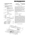
A handheld ultrasound'device is provided, havinga trans
ducer assembly for emitting and rece1vmg son1c s1gnals, a
(52) US“ Cl“
con?gurable signal processing unit, and a data processor
CPC ............... .. A61B 8/00 (2013.01); A61B 8/4455
con?gured to provide con?guration data to the Signal pro
(201301); A613 8/462 (201301); A613 8/465
cessing unit. The con?guration data de?nes a beamforming
(201301)
con?guration, ?ltering con?guration and envelope detection
USPC ......................................... .. 600/446; 600/443
Field of Classi?cation Search
con?guration for an operational mode. The operational mode
may be selected by the user or may be determined based on a
See application ?le for complete search history.
detected type of the transducer assembly.
20 Claims, 8 Drawing Sheets
(58) None
meet/w
ms
i
5
ENE FLQQEMENT
"
“5
£252FTWAR€
i
32
" ~~ $5.4
1
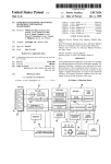
LINE PiAE?EME¢VTiMAG/NG
S'EGUE'I’WIE QM? GU3DE
~ 1.
“'~-~ 1:3,}
a
,...~ 24
951,15 IVE VGAE ant} {tilts '
KRPa
1
'f HANSOUEJKQ
m
US 8,920,325 B2
Page 2
(56)
References Cited
US PATENT DOCUMENTS
2005/0228281 A1 *
10/2005 Nefos ......................... .. 600/446
2007/0073155 A1
3/2007 Park et a1.
2007/0161904 A1*
7/2007
2008/0221446 A1*
9/2008 Washburn et a1. .......... .. 600/437
* cited by examiner
Urbano ....... ..
.. 600/459
US. Patent
Dec. 30, 2014
I
US 8,920,325 B2
DISPLAY
J
/
Sheet 1 0f8
\
CONTROLS
[/08
k 32
\
PROCESSOR, MEMORY and
EMBEDDED 05
28
y
\
RM
L16
30
PREPROCESSING and
\L
DIGITAL BEAMFORMEF? FPGA
M
f
18
’29
RECEIVE VCAS and A/DS \L
24
22 ,J’
TRANS/WT PULSERS
I
‘1 26
20
TRANSDUCER
FIG. 1
US. Patent
Dec. 30, 2014
Sheet 2 0f8
US 8,920,325 B2
US. Patent
Dec. 30, 2014
Sheet 3 0f8
US 8,920,325 B2
U.S. Patent
Dec. 30, 2014
Sheet 4 0f8
US 8,920,325 B2
US. Patent
Dec. 30, 2014
Sheet 5 0f 8
US 8,920,325 B2
1r
't
away m zwmg
US. Patent
Dec. 30, 2014
Sheet 6 0f8
US 8,920,325 B2
3
'mew m; am y
,
Q.
-
My“
my
F7624
'3
.
v
--
MM
76
US. Patent
Dec. 30, 2014
Sheet 7 0f 8
US 8,920,325 B2
.1
é
aga
mmazwsw
$56
US. Patent
Dec. 30, 2014
Sheet 8 0f8
US 8,920,325 B2
US 8,920,325 B2
1
2
HANDHELD ULTRASOUND IMAGING
SYSTEMS
sound systems. Ultrasound systems described in the patent
literature include the following US patents:
US. Pat. No. 5,295,485 to Shinomura et al. describes a
handheld ultrasound imaging system that canbe adapted
REFERENCE TO RELATED APPLICATIONS
m
This application is a continuation of US. patent applica
tion Ser. No. 12/188,122 ?led 7 Aug. 2008, which claims the
bene?t under 35 U.S.C. §119 of US. patent application No.
60/977,353 ?led 3 Oct. 2007, all of which are entitled HAND
to support multi element array transducers and includes
a beamformer.
US. Pat. No. 5,722,412 to P?ugrath et al., US. Pat. No.
5,817,024 to Ogle et al., and US. Pat. No. 6,203,498 to
Bunce et al. describe handheld ultrasound systems built
aron a set of ASIC (Application Speci?c Integrated
Circuit) chips. The systems include a transducer array,
HELD ULTRASOUND IMAGING SYSTEMS and are
hereby incorporated by reference. This application claims the
bene?t under 35 U.S.C. §120 of US. patent application Ser.
No. 12/188,122 ?led 7 Aug. 2008 and entitled HANDHELD
an ASIC transmit/receive front end, an ASIC that
includes digitization and digital beamforming capabili
ULTRASOUND IMAGING SYSTEMS.
ties, an ASIC for signal processing and an ASIC for
display processing.
TECHNICAL FIELD
US. Pat. Nos. 6,251,073 and 6,569,102 to Imran et al.
describe a handheld ultrasound system that can con
This invention relates to medical monitoring systems. The
invention relates particularly to systems which apply ultra
sound to detect physiological features or characteristics of a
20
The handheld system has the ability to output a diagnos
subject. Embodiments of the invention provide handheld
ultrasound imaging devices.
tic image built from multiple transmit/receive acquisi
tions.
US. Pat. Nos. 5,590,658, 6,106,472, and 6,638,226 to
Chiang et al. describe a handheld ultrasound system that
BACKGROUND
Ultrasound imaging systems are used in medicine to
includes a transducer coupled to a CCD-based analog
explore internal areas of a subject’s body. Ultrasonic imaging
is non-destructive and versatile and can provide high quality
beamformer and post processing electronics. The sys
tem uses a separate back-end to further process and
diagnostic images.
A typical medical ultrasound imaging system has a trans
struct an image built from multiple transmit/receive
acquisitions that are temporarily stored in a memory.
display diagnostic images.
30
US. Pat. No. 7,115,093 to Halmann et al. describes a
ducer, a custom built electronic controller, and a user inter
handheld ultrasound imaging system comprising a
face. The transducer typically comprises an array of at least
detachable scanhead coupled to a traditional beamform
ing module, that is connected via a USB (Universal
Serial Bus) port to a commercially available PDA (Por
several regularly-spaced piezoelectric transducer elements.
The transducer elements may be arranged in any of several
different geometries, depending upon the medical application
35
for which the transducer will be used.
The controller drives the transducer to emit ultrasound
signals and collects and processes data from the transducer to
provide, store, display and manipulate images. The user inter
faces for typical ultrasound imaging systems typically
table Digital Assistant). The PDA performs post pro
cessing functions to yield ultrasound images.
The inventors have recognized a need for a handheld ultra
sound imaging device that is cost effective and can be con
40
?gured to operate in multiple different modes to address
different application-speci?c needs.
include various input/output devices which allow a user to
control the operation of the imaging system. The input/ output
BRIEF DESCRIPTION OF THE DRAWINGS
devices typically comprise at least a control panel, a video
display, and a printer.
The electronic controller can send and receive electric sig
Non-limiting example embodiments are illustrated in the
45
closed herein are examples that illustrate ways in which the
invention may be implemented. The invention is not limited
to the illustrated embodiments.
nals to and from any of the transducer elements. To create a
diagnostic image, the controller transmits electrical excita
tion signals to the transducer elements. The transducer ele
ments convert the excitation signals into ultrasonic vibra
tions, which are transmitted into the subject’s body. The
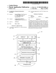
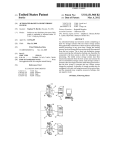
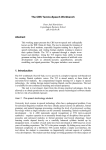
FIG. 1 is a block diagram illustrating major functional
50
ultrasonic vibrations typically have frequencies in the range
of about 2 MHZ to about 12 MHZ. The ultrasonic vibrations
are scattered and re?ected by various structures in the sub
ject’s body. Some of the re?ected and/ or scattered ultrasonic
vibrations, which may be called echoes, are received at the
accompanying drawings. The embodiments and ?gures dis
55
components of a ultrasound imaging device according to an
embodiment of the invention.
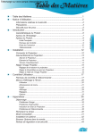
FIGS. 2A, 2B and 2C illustrate an ultrasound imaging
device according to an example embodiment of the invention
equipped with different transducer assemblies for use in dif
ferent operational modes. In FIG. 2A the transducer assembly
transducer. The echoes cause the transducer elements to gen
has elements arranged in a convex array. In FIG. 2B the
erate electrical signals. After the excitation signals have been
transducer assembly has elements arranged in a linear array.
In FIG. 2C the transducer assembly has elements arranged to
provide a phased array.
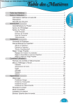
FIG. 3 is a ?ow chart illustrating a method for initializing
an imaging device according to an embodiment of the inven
tion.
transmitted the controller receives and processes the electric
signals from the transducer elements.
The resulting image is displayed in real time on a display.
The classic presentation of the display, called B-mode, is a
60
two-dimensional image of a selected cross-section of the
patient’s body. Modern ultrasound systems also provide
?ow-imaging modes such as Color Doppler and Pulsed Dop
pler, which show and can help to quantify blood ?ow.
Recent miniaturization of electronics has enabled the
design of a generation of lighter, portable or handheld ultra
FIG. 4 is a more detailed view illustrating features of a
65
processor unit and a signal processing unit in an example
embodiment.
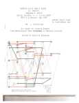
FIG. 5A is a block diagram illustrating an ultrasound imag
ing device con?gured for line placement and FIG. 5B is an
US 8,920,325 B2
4
3
example of an image that could be generated by the ultra
sound imaging device of FIG. 5A.
WIRELESS NETWORK HAVING PORTABLE ULTRA
SOUND DEVICES (claiming priority from application
No. 60/955,331)
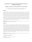
FIG. 6A is a block diagram of an ultrasound imaging
all of which are hereby incorporated herein by reference.
device con?gured for monitoring labour and delivery in
obstetrics applications and FIG. 6B is an example of an image
5
of the type that could be produced by the ultrasound imaging
FIG. 1 shows an ultrasound imaging device 10 according to
an example embodiment of the invention. Device 10 has a
housing 12 containing electronic circuitry which controls
device of FIG. 6A.
transducer elements in a transducer assembly 20 to transmit
ultrasound signals into a subject. The electronic circuitry also
receives ultrasound signals that have been re?ected from
within the subject and processes those ultrasound signals to
yield an image.
Device 10 comprises a display 14 upon which an image
DESCRIPTION
Throughout the following description speci?c details are
set forth in order to provide a more thorough understanding to
persons skilled in the art. However, well known elements may
may be displayed, a processor unit 16 which may comprise a
not have been shown or described in detail to avoid unneces
data processor, memory and associated operating system, and
a con?gurable signal processing unit 18. Under the control of
processor unit 16, signal processing unit 18 may be con?g
sarily obscuring the disclosure. Accordingly, the description
and drawings are to be regarded in an illustrative, rather than
a restrictive, sense.
An example embodiment of the invention provides a hand
holdable ultrasound imaging device that can be con?gured to
ured to provide signal processing appropriate to different
operational modes.
20
perform a range of speci?c ultrasound imaging procedures.
The device preferably has a form-factor that permits it to be
carried in a shirt pocket. The device may provide a simpli?ed
obtaining at least basic information about fetus position
prior to and during delivery in labour and delivery
user interface for each operational mode so that it can be used
by personnel who may not have extensive training The dif
Some examples of different operational modes are modes
tailored to:
rooms;
25
monitoring a position of a needle in biopsy line placement
and optionally providing a biopsy guide display;
ferent operational modes may be selected for use in different
point of care settings, where a practitioner is interested in
screening for conditions such as Abdominal Aortic Aneu
looking inside patients’ bodies for gathering anatomy infor
mation, monitoring vital functions, targeting a particular
body structure, observing organ con?gurations, looking at
the like.
Device 10 optionally includes a stored user manual and/or
rysm; and,
30
a stored audio and/or visual user guide that can be played to a
user on device 10. The user manual and user guide may
fetal positions or the like.
The features of the invention described herein may be
combined in any suitable combinations with the features
described in the commonly-owned US provisional patent
applications entitled:
HAND-HELD ULTRASOUND
35
SYSTEM HAVING
STERILE ENCLOSURE (application No. 60/ 955,327);
HAND-HELD ULTRASOUND IMAGING DEVICE
HAVING RECONFIGURABLE USER INTERFACE
40
(application No. 60/955,328);
POWER MANAGEMENT IN PORTABLE ULTRA
SOUND DEVICES (application No. 60/ 955,329);
HAND-HELD ULTRASOUND IMAGING DEVICE
HAVING REMOVABLE TRANSDUCER ARRAYS
45
WIRELESS NETWORK HAVING PORTABLE ULTRA
50
patent applications which are ?led on the same day as the
instant application and entitled:
55
STERILE ENCLOSURE (claiming priority from appli
cation No. 60/955,327);
60
POWER MANAGEMENT IN PORTABLE ULTRA
SOUND DEVICES (claiming priority from application
No. 60/955,329);
HAND-HELD ULTRASOUND IMAGING DEVICE
HAVING REMOVABLE TRANSDUCER ARRAYS
(claiming priority from application No. 60/955,325);
and,
voltage controlled ampli?ers, and the like to condition incom
ing signals. Signal conditioning stage 24 also includes one or
more analog to digital converters which digitize the signals
picked up by elements of transducer assembly 20 and pass the
digitized signals 29 to signal processing unit 18.
Within signal processing unit 18, signals 29 are entirely or
HAND-HELD ULTRASOUND IMAGING DEVICE
HAVING RECONFIGURABLE USER INTERFACE
(claiming priority from application No. 60/ 955,328);
Transducer assembly 20 has elements which pick up
re?ected ultrasound signals. These re?ected signals are
passed through interface 26 to receive signal conditioning
stage 24. Signal conditioning stage 24 may include ?lters,
described in the commonly-owned US non-provisional
SYSTEM HAVING
signal processing unit 18 (using control signals 19) which
path 28).
SOUND DEVICES (application No. 60/955,331)
all of which are hereby incorporated herein by reference. The
HAND-HELD ULTRASOUND
generate driving signals for transducer elements in transducer
assembly 20. The driving signals are delivered to transducer
assembly 20 by way of interface 26. The timing, phases,
intensities and/or other characteristics of the driving signals
may be set to provide ultrasonic signals appropriate to the
current operational mode. For example, the timing, phases,
intensities and/or other characteristics of the driving signals
delivered to transducer assembly 20 may be controlled by
may in turn be con?gured for the current operational mode by
processing unit 16 (using appropriate control signals on data
(application No. 60/955,325); and
features of the invention described herein may also be com
bined in any suitable combinations with the features
explain use of device 10 in the current operational mode.
When device 10 is operating in an operational mode, pro
cessor unit 16 interacting with signal processing unit 18 gen
erates control signals 19 which cause transmit pulsers 22 to
partially processed and then passed on data connection 30 to
processor unit 16 which displays the resulting image on dis
play 14 or, in the alternative, provides further processing of
the signals on data path 30 (i.e. from signal processing unit
18) and then displays the resulting image on display 14.
In some embodiments the signals passed to processor unit
65
16 by signal processing unit 18 (on data path 30) comprise RF
data (e. g. data provided at a rate that is two or more times the
frequency of the ultrasound emitted by transducer assembly
US 8,920,325 B2
5
6
20). In such embodiments, processor unit 16 performs further
processing to derive image data from the RF data. By way of
non-limiting example, processor unit 16 may perform func
tions such as: frequency analysis of the received signals (by
controls 34. Control 34 may, for example, comprise an on/off
switch for the purpose of turning device 10 on and shutting
device 10 off.
In some embodiments, display 14 comprises a touch-sen
sitive display and controls for operating device 10 may be
provided in the form of touch-sensitive areas on display 14
and/or by way of the capability of device 10 to recognize
gestures or other patterns of contact between a user’s ?nger,
or a stylus and display 14.
A bene?t of the architecture described herein is that it
permits the same hardware to be con?gured in different man
ners (e.g. different operational modes) so as to provide dif
way of a fast Fourier transform (FFT) algorithm, for
example); auto-correlation; and the like in addition to or as
part of obtaining the image data.
In modes which involve Doppler imaging, signal process
ing unit 18 may be con?gured to perform digital wall ?ltering
and/ or auto-correlation.
As is apparent from the above, some functions that are
required in the signal path for certain operational modes may
be performed either by processor unit 16 or by signal pro
ferent specialized imaging functions. For example, ultra
sound device 10 may be con?gured to provide imaging
cessing unit 18. In some cases, performance may be increased
by performing functions such as ?ltering, envelope detection,
suitable for use in monitoring a fetus prior to and during
labour and delivery. The same device 10 may be con?gured
log compression, auto-correlation in processor unit 16. This
may permit additional functions to be provided in signal
processing unit 18 in those cases where the capacity of signal
processing unit 18 is limited.
In some embodiments, signal processing unit 18 is con?g
needle, such as a needle for taking a biopsy or some other type
of needle into a tissue or other physiological structure of
differently to provide imaging that is optimized for guiding a
20
ured to perform beamforming on at least the signals received
from transducer assembly 20. In some embodiments, in addi
Each operational mode may have associated with it a num
ber of different elements. These may include, for example:
tion to beamforming, signal processing unit 18 performs ?l
tering and/or envelope detection on the signals received from
transducer assembly 20.
In those embodiments where signal processing unit 18
performs ?ltering of the signals received from transducer
assembly 20, signal processing unit 18 may be con?gurable to
implement digital ?lters having different ?lter coef?cients for
25
transducer assembly 20 in such a way as to provide
ultrasound images appropriate to the operational mode;
user interface controls which are speci?c to the operational
30
erly using device 10 in the operational mode. The help
functions include images and videos for display on the
?lter coef?cients may be selected to pass signals having fre
35
volume manufacture of the platform even in cases where
some of the individual operational modes may be very spe
40
In those embodiments where signal processing unit 18
performs envelope detection on the signals received from
transducer assembly 20, signal processing unit 18 may be
con?gurable to select from among a plurality of different
45
user interface controls 15 on display 14 and/or by changing
functions assigned to any interface controls not provided by
display 14 permits the device 10 to offer a simpli?ed and
highly effective user interface in each of its available special
In some embodiments, a device 10 can be locked in a
signals.
selected operational mode. Such a device may be sold at a
50
sound device 10 in data communication with one or more
other devices. Input/output interface(s) 32 may comprise one
relatively low cost without disrupting the market for devices
10 con?gured to perform in other operational modes.
The user interface may be provided as described in co
pending US. Patent Application No. 60/955,328 entitled
Hand-held Ultrasound Imaging Device Having Recon?g
or more wireless interfaces (which may, for example, com
prise RF wireless interfaces, infrared wireless interfaces or
the like) or other connections such as serial connections, USB
connections, parallel connections, or the like. In some
cialized and in relatively low demand. Furthermore, the abil
ity to specialize the device under software control by adding
and/or removing and/or repositioning and/or recon?guring
ized operational modes.
signal connections) within a section of an FPGA that imple
ments one or more envelope detectors that act on the received
Input/ output interface(s) 32 may be provided to place ultra
display.
The ability to con?gure a single hardware platform to
provide a range of specialized operational modes permits
?guring signal processing unit 18 may comprise program
ming interconnects (e.g. signal connections) within a section
of a ?eld-programmable gate array (FPGA) that implements
envelope detection algorithms. Recon?guring signal process
ing unit 18 may comprise programming interconnects (e.g.
mode;
various help functions provided by device 10 which are
speci?c to the operational mode to assist users in prop
to provide a good signal-to-noise ratio for each speci?c appli
cation (e.g. each speci?c operational mode). For example, the
one or more digital ?lters for the received signals.
speci?c con?gurations of signal processing unit 18 and/or
transmit pulsers 22 to generate speci?c ultrasound sig
nals and to process resulting re?ected signals detected at
different applications. The ?lter coef?cients may be selected
quencies in a band around a frequency at which elements of
transducer assembly 20 are driven to emit ultrasound. Recon
interest. Other operational modes may be provided for some
other speci?c purposes.
55
urable User Interface (?led on 10 Aug. 2007) or its counter
part US non-provisional application of the same title (?led on
embodiments, device 10 has wireless connectivity according
the same date as the instant application) both of which are
to the BluetoothTM standard or an IEEE 802.11 standard (oth
hereby incorporated herein by reference.
erwise known as WIFI).
FIG. 2A shows a handheld ultrasound imaging device 10
according to an example embodiment of the invention.
Device 10 has a housing 12 which is suitably small enough to
In some cases for different operational modes it is desirable
weigh less than 10 pounds (i.e. 4.5 kg). A display 14 is
to provide different arrangements of transducer elements in
transducer assembly 20. For this purpose, device 10 may be
con?gured to permit the use of interchangeable transducer
assemblies 20 that may be removed and replaced with differ
ent transducer assemblies suitable for different operational
modes. For example, device 10 may be con?gured as
described in US. Patent Application No. 60/955,325 entitled
provided on housing 12 as are one or more user interface
Hand-held Ultrasound Imaging Device Having Removable
60
be hand carried, and preferably is small enough to keep in a
person’s pocket. For example, housing 12 may have dimen
sions of approximately 10 cm><8 cm><2 cm, and device 10 may
65
US 8,920,325 B2
7
8
Transducer Arrays (?led on 10 Aug. 2007) or its counterpart
US non-provisional application of the same title (?led on the
subject or, in the alternative, may be invoked by means of a
same date as the instant application) both of which are hereby
FIG. 4 shows, in more detail, processor unit 16 and signal
processing unit 18 according to a particular embodiment.
suitable user interface control.
incorporated herein by reference.
In such cases, device 10 may be con?gured so that it auto
Processor unit 16 comprises one or more suitable data pro
matically switches between operational modes in response to
detecting that a transducer assembly 20 has been changed to
a different type of transducer assembly. In the alternative,
comprise a suitable microprocessor, digital signal processor
device 10 can perform a routine to detect the type of con
nected transducer assembly 20, either on initialization or at
some other time and can select an appropriate operational
(DSP), image processor, or the like. In an example embodi
ment, data processor 55 comprises a BlackFinTM digital sig
nal processor available from Analog Devices, Inc. of Nor
mode based upon information identifying the type of trans
ducer assembly 20 identi?ed in the initialization routine.
FIGS. 2A, 2B and 2C show, for example, a device 10 to
which different transducer assemblies 20, 20A and 20B have
been attached respectively. A different operational mode may
correspond to each of transducer assemblies 20, 20A and
20B. Device 10 may be switched between these operational
wood Mass.
modes by selecting and installing the corresponding trans
ducer assembly.
cessor(s) 55ia single data processor 55 is shown in the
illustrated embodiment. Data processor 55 may, for example,
Processor 55 is capable of executing software instructions
which may be stored in memory 57 accessible to processor 55
or which may be otherwise accessible to processor 55. In the
illustrated embodiment, memory 57 contains an operating
system 58A and con?guration data 58B for one or more
operational modes. Memory 57 may also have capacity to
20
Processor 55 can cause con?guration data (e.g. for a par
In other embodiments, a device 10 may be switched
between operational modes by means of a control provided on
a user interface. In still other embodiments, device 10 is
intended to offer a single speci?c operational mode. Device
25
10 may be upgraded to provide enhanced features or to work
according to some different operational mode by uploading
new con?guration data to device 10 by way of input/output
interface(s) 32. In some embodiments, device 10 stores con
?guration data on a removable medium such as a card, chip,
memory stick, memory or the like. In such embodiments it
store patient data 58C (e.g. images, information identifying
patients, or the like).
30
ticular operational mode and/or for a particular type of trans
ducer array 20) to be delivered to signal processing unit 18 by
data path 28 or directly from a memory 57 to signal process
ing unit 18 by way of a suitable bus (e.g. bus 59) connected to
deliver the con?guration data from memory 57 to signal pro
cessing unit 18. Such con?guration data may comprise all or
a part of con?guration data 58B stored in memory 57. The
con?guration data may cause suitable interconnects (e. g. sig
nal processing paths) to be created within signal processing
may be possible to upgrade an existing operational mode or
unit 18 for the purpose of generating suitable transmitted
add or change to a new operational mode by replacing the
removable medium 17 with a removable medium that has
ultrasound signals and processing received ultrasound signals
con?guration data for the new or upgraded operational mode.
In some embodiments, device 10 may have con?guration data
in such a manner as to produce an image appropriate for the
35
current operational mode.
In the embodiment illustrated in FIG. 4, signal processing
for a number of different operational modes but some of the
unit 18 is con?gured by con?guration data delivered by way
operational modes may be locked out until a password, digital
key, or other authorization code is provided to release the
functionality of some of the operational modes.
receive beamformer 62. Depending upon the operational
of data path 28 to provide a transmit beamformer 60 and a
a device 10 as described above is turned on. In block 42 the
mode, transmit beamformer 60 and receive beamformer 62
may comprise different numbers of channels and may be
con?gured in different ways to provide different characteris
device is turned on. In block 44, device 10 initializes itself by
tics of the transmitted ultrasound signal as well as to derive
starting to run its operating system and then invoking embed
ded software which coordinates the overall operation of
device 10 (e.g. on a processor ofprocessor unit 16). In block
46, the type of transducer assembly 20 that is connected to
device 10 is determined (either by detecting information iden
different information from received ultrasound signals.
Processor unit 16 may be con?gured to synchronize the
transmission and reception of ultrasound signals by trans
40
FIG. 3 shows a method 40 that may be implemented when
ducer assembly 20. In such embodiments, synchronization
signals may be provided by way of data path 28.
When a received ultrasound signal is passed to signal pro
tifying the transducer assembly 20 or in some embodiments
by receiving user input).
In block 48, the con?guration data for the operational mode
corresponding to the transducer assembly 20 recognized in
block 46 is read and, in the illustrated embodiment, signal
processing unit 18 is con?gured according to the con?gura
tion data in block 50. The con?guration data may additionally
50
55
specify software to be run on processor unit 16 to support
imaging in the corresponding operational mode. In block 50,
the transmit and receive circuitry (i.e. transmit pulsers 22 and
receive signal processing stage 24) may be shut down and
placed in a standby mode waiting for instructions to com
mence imaging.
Although not speci?cally shown in FIG. 3, user interface
60
operational mode may also be loaded by processor Lmit 16 as
Imaging may commence automatically upon device 10
detecting that transducer assembly 20 is in contact with a
receive beamformer 62 and the resulting data is passed to
processor unit 16 by way of data connection 30. Processor 55
processes the data that it receives in a manner speci?ed by the
con?guration data 58B associated with the current opera
tional mode and displays the resulting data on display 14 in
the form of a suitable display. Processor 55 may optionally
also store the image data in memory 57 and/or transmit the
image data to a network or other device by way of input/
output interface(s) 32.
In some embodiments, signal processing unit 18 comprises
a ?eld programmable gate array (FPGA) that is connected to
a memory 57 by a bus 59. Memory 57 may store con?guration
data 58B. Such con?guration data 58B may comprise con
controls and/ or user manual information associated with the
a part of method 40 or otherwise.
cessing unit 18, the received signal is processed by way of
?guration data associated with one or more operational
65
modes. By way of non-limiting example, the con?guration
data associated with each operational mode may comprise
information specifying one or more of:
US 8,920,325 B2
10
delivery software and signal processing unit 18B is con?g
transmit beamforming parameters;
receive beamforming parameters;
ured to generate ultrasound signals and process detected
?ltering parameters;
ultrasound signals in ways suitable for providing good quality
envelope detection parameters;
images of a fetus in utero and/or in the birth canal.
A device 10 may usefully include features as described in
etc.
co-pending U.S. Application No. 60/955,329 entitled Power
All con?guration data 58B may be stored in memory 57.
Memory 57 may, for example, comprise a ?ash memory or
the like. Providing a single memory 57 that contains all con
Management in Portable Ultrasound Devices (?led on 10
Aug. 2007) or its counterpart US non-provisional application
?guration data 58B simpli?es construction and potentially
of the same title (?led on the same date as the instant appli
reduces power consumption. Processor unit 16 may control,
directly or indirectly, what portion of con?guration data 58B
is loaded from memory 57 into signal processing unit 18. The
portion of con?guration data 58B loaded into signal process
ing unit 18 may be associated with a particular operational
mode.
cation) both of which are hereby incorporated herein by ref
erence. These applications describe the use of con?guration
data to place an ultrasound device in different operational
modes as well as to use con?guration data to place the ultra
sound device in various power consumption modes.
As discussed above, signal processing unit 18 may com
Some embodiments provide the option of con?guring sig
nal processing unit 18 differently for each line of an ultra
sound image. In some such embodiments, con?guration data
for all lines of the ultrasound image may be stored in memory
57 and retrieved by way of bus 59 (or data connection 28) on
an as-needed basis. For example, signal processing unit 18
may comprise a buffer that holds con?guration data for a
current ultrasound image line and also has space to receive
prise an FPGA. Advantageously, the same FPGA may be
con?gured to both generate control signals for transmit
pulsers 22 and to provide processing of detected signals
received from elements of transducer assembly 20. Providing
20
because it reduces the width of the signal path required
between processor unit 16 and signal processing unit 18.
Example embodiments of the invention may be made from
readily-available off the shelf components as contrasted with
con?guration data for one or more subsequent ultrasound
image lines. The con?guration data for the subsequent ultra
25
sound image lines may be read into the buffer from memory
57 while the current ultrasound image line is being processed
according to con?guration data in the buffer. To facilitate such
Where a component (e.g. a processor, circuit, beamformer,
30
Some or all of the con?guration data 58B stored in memory
57 may be generated by processor 55 executing suitable soft
should be interpreted as including as equivalents of that com
ponent any component which performs the function of the
described component (i.e., that is functionally equivalent),
35
controls may be provided so that a user can de?ne features of
the operational mode. The resulting coef?cients may then be
saved into memory 57 so that they are available to be loaded
for con?guration of signal processing unit 18 when the user
de?ned operational mode is invoked.
40
FIG. 5A shows an example of a device 10 which has been
con?gured to provide a line placement operational mode and
FIG. 5B shows an example of a resulting image 66 when
device 10 is so con?gured. In the illustrated embodiment, line
placement software executes on processor unit 16A and sig
etc.) is referred to above, unless otherwise indicated, refer
ence to that component (including a reference to a “means”
ware instructions. For example, processor 55 may execute
software for calculating ?ltering coef?cients and/or beam
forming coef?cients for a particular operational mode. User
custom circuitry such as complicated application speci?c
integrated circuits (ASICS) which are required to provide
specialized functions in other devices.
signal conditioner, ?lter, control, assembly, device, circuit,
operation, the buffer may be set up as a circular buffer or
‘ping-pong’ buffer, for example.
both of these functions in a single FPGA is advantageous
including components which are not structurally equivalent
to the disclosed structure which performs the function in the
illustrated exemplary embodiments of the invention. The
embodiments described above and depicted in the Figures are
examples only. Features of those embodiments may be com
bined in ways other than those expressly set out herein.
While a number of exemplary aspects and embodiments
have been discussed above, those of skill in the art will rec
ognize certain modi?cations, permutations, additions and
sub-combinations thereof. It is therefore intended that the
45
following appended claims and claims hereafter introduced
nal processing unit 18A is con?gured in such a manner as to
are interpreted to include all such modi?cations, permuta
provide line placement imaging sequence and guide func
tions. In this operational mode, signal processing unit 18A
tions, additions and sub-combinations as are within their true
spirit and scope.
may be con?gured with beamforming coef?cients that result
in enhanced visibility in an image 66 of a needle 66B or the
50
FIG. 5B shows an example of an image 66 which could be
provided on display 14 during operation of device 10 when it
is in the line placement operational mode of FIG. 5A. Image
66 includes depictions 66A of various anatomical structures
in the subject, an image of a needle or probe 66B, and gener
ated guide lines 66C which indicate a desired placement of
the needle or probe. Parameters used to generate guidelines
66C may be speci?ed in con?guration data and/or in software
executing on processor unit 16.
What is claimed is:
1. A hand-holdable ultrasound system comprising:
a detachable transducer assembly comprising a plurality of
transducer elements, the detachable transducer assem
like (FIG. 5B) being inserted into a subject.
55
bly interchangeable with one or more other detachable
transducer assemblies, the detachable transducer assem
bly and the one or more other detachable transducer
assemblies are suitable for ultrasound imaging in a
respective one of a plurality of different operational
modes of the ultrasound system, the detachable trans
60
ducer assembly not attached to or part of a transducer
FIG. 6A illustrate a device 10 con?gured to operate in a
probe, and the detachable transducer assembly attaches
labour and delivery operational mode which is intended for
directly to the hand-holdable ultrasound system and not
through a transducer probe;
a driving circuit operable to deliver driving signals to excite
the transducer elements of the transducer assembly to
emit ultrasound signals, the driving circuit comprising a
monitoring the labour or pregnant women and the delivery of
babies in obstetric applications and FIG. 6B shows an
example of a resulting image 68 which may be provided on
display 14 when device 10 is so con?gured. In this embodi
ment, processor unit 16B is con?gured to execute labour and
65
plurality of transmit pulsers;
US 8,920,325 B2
11
12
receive beamformer, the transmit beamformer and
receive beamformer having different numbers of chan
a receive circuit operable to receive re?ected ultrasound
signals detected at the transducer assembly and to con
nels;
dition the received re?ected ultrasound signals to yield
conditioned signals, the receive circuit comprising one
or more analog to digital converters arranged to digitize
the received re?ected ultrasound signals;
a con?gurable signal processing unit connected to receive
the digitized conditioned signals and to process the con
the plurality of operational modes comprises a line place
ment operational mode, one of the sets of con?guration
data comprises line placement con?guration data, and
the ultrasound system is con?gured according to the line
placement con?guration data to provide imaging that is
optimized for guiding a needle into a tissue or another
ditioned signals, the con?gurable signal processing unit
physiological structure, the line placement con?gura
comprising
tion data specifying line placement software to be
executed by the processor unit and con?gured to con?g
ure the signal processing unit with beamforming coe?i
cients, one or both of the line placement con?guration
data and the line placement software comprising param
eters for generating guidelines on the display to indicate
a ?eld programmable gate array;
a processor unit comprising one or more data processors
and
a memory, the memory storing software instructions for
execution by the one or more processors and pre
stored with a plurality of sets of con?guration data,
each of the plurality of sets of con?guration data
corresponding to a different one of the operational
modes of the plurality of operational modes;
20
a display operable to display an image based at least in part
sions less than about 15 centimeters and a width less than
about 5 centimeters.
3. The hand-holdable ultrasound system according to claim
on the re?ected ultrasound signals detected at the trans
ducer assembly; and
1 wherein each of the sets of con?guration data provides:
one or more user interface controls for providing user input
to the hand-holdable ultrasound system;
25
wherein the software instructions are con?gured to cause
the one or more data processors to: identify a type of the
detachable transducer assembly; based on the identi?ed
type of the detachable transducer assembly, select a
respective one of the plurality of operational modes cor
responding to the identi?ed type of the detachable trans
a desired placement of athe needle.
2. The hand-holdable ultrasound system according to claim
1 wherein the hand-holdable ultrasound system weighs less
than 10 pounds and has transverse and longitudinal dimen
a speci?c con?guration of the signal processing unit and
the transmit pulsers to generate speci?c ultrasound sig
nals and to process resulting re?ected signals detected at
the transducer assembly to provide ultrasound images
appropriate to the corresponding operational mode;
30
user interface controls which are speci?c to the corre
sponding operational mode; and help functions speci?c
ducer assembly for which the ultrasound system will be
to the corresponding operational mode to assist users in
con?gured; and con?gure each of: the signal processing
properly using the ultrasound system in the correspond
unit, the transmit circuit, the processor and the user
interface controls according to the one of the sets of
ing operational mode, the help functions comprising
35
con?guration data corresponding to the selected opera
tional mode; wherein:
the sets of con?guration data for different ones of the
plurality of operational modes are con?gured to con?g
ure the signal processing unit to implement digital ?lters
having different ?lter coef?cients to provide ?ltering of
the conditioned re?ected ultrasound signals received
from the transducer assembly;
the set of transducer assemblies, the set of transducer assem
40
45
assembly comprising a linear array of transducer elements
and a third transducer assembly comprising a phased array of
transducer elements.
5. The hand-holdable ultrasound system according to claim
1 comprising one or more input/output interfaces for receiv
ing the con?guration data, prior to storing the con?guration
data in the memory, into the hand-holdable ultrasound system
ducer assembly;
the set of con?guration data for at least one of the opera
tional modes is con?gured to identify software to be run
on the processor unit to support imaging in the corre
blies comprising a ?rst transducer assembly comprising a
convex array of transducer elements, a second transducer
the set of con?guration data for at least one of the opera
tional modes is con?gured to con?gure the ?eld pro
grammable gate array to both generate control signals
for the transmit circuit and to provide processing of
detected signals received from elements of the trans
images and videos for display on the display.
4. The hand-holdable ultrasound system according to claim
1 wherein the ultrasound system comprises a set of transducer
assemblies and the detachable transducer assembly is one of
wherein the one or more input/output interfaces comprise at
50
least one of: an interface to a removable memory medium; a
wireless communication interface; a serial data interface; a
the set of con?guration data for at least one of the opera
parallel data interface; and a universal serial bus interface.
6. The hand-holdable ultrasound system according to claim
1 wherein the memory comprises a removable memory
medium and the con?guration data is stored on the removable
memory medium.
7. The hand-holdable ultrasound system according to claim
tional modes is con?gured to con?gure the signal pro
1 wherein, for each of the plurality of operational modes the
sponding operational mode, the software con?gured to
cause the processor unit to perform one or more of:
?ltering, envelope detection, log compression, and auto
correlation;
55
one or more user interface controls comprise a user interface
cessor unit to pass RF data to the processor unit at a rate
that is two or more times a frequency of the ultrasound 60 control con?gured for providing a help request to the hand
signals and to con?gure the processor unit to perform
further processing to derive image data from the RF data
by one or more of: fast Fourier transform of the RF data
and auto-correlation; or
the set of con?guration data for at least one of the opera
holdable ultrasound system and wherein the processor unit is
con?gured to respond to the help request in a manner which is
speci?c to a current one of the plurality of operational modes.
8. The hand-holdable ultrasound system according to claim
tional modes is con?gured to con?gure the signal pro
1 wherein the display comprises one or more touch-sensitive
user interface controls for providing user input to the hand
cessor unit to provide a transmit beamformer and a
holdable ultrasound system and the processor unit is con?g
65
US 8,920,325 B2
13
14
ured to add, remove, reposition and recon?gure the user inter
signal processing unit Which has been con?gured for the
current operational mode by the processor unit.
face controls on the display under software control on
switching among the operational modes.
15. The hand-holdable ultrasound system according to
9. The hand-holdable ultrasound system according to claim
1 Wherein, for at least a ?rst one of the plurality of operational
claim 1 Wherein for at least one of the operational modes the
modes, the processor unit is con?gured to provide con?gura
tion data to the signal processing unit to con?gure the signal
processing unit to provide different signal processing opera
detection on the signals received from the transducer assem
signal processing unit is con?gured to perform envelope
bly.
16. The hand-holdable ultrasound system according to
claim 15 Wherein the signal processing unit is con?gurable to
provide an envelope detection algorithm from among a plu
tions for different lines of an ultrasound image.
10. The hand-holdable ultrasound system according to
claim 9 Wherein for the ?rst one of the operational modes
con?guration data for all lines of an ultrasound image is
stored in the memory and the signal processing unit is con
?gured to retrieve the con?guration data for the lines of the
rality of different envelope detection algorithms by program
ultrasound image on an as-needed basis.
11. The hand-holdable ultrasound system according to
claim 10 Wherein the set of con?guration data for the ?rst one
of the operational modes is con?gured to con?gure the signal
processing unit to provide a buffer that holds con?guration
data for a current ultrasound image line Wherein the buffer
20
also has space to hold con?guration data for one or more
nals and providing the synchronization signals to the signal
processing unit.
12. The hand-holdable ultrasound system according to
claim 11 Wherein the set of con?guration data for the ?rst one
25
modes, timing, phases, and intensities of the driving signals
delivered to the transducer assembly are controlled by the
19. The hand-holdable ultrasound system according to
claim 1 Wherein the con?guration data associated With each
of the plurality of operational modes comprises information
specifying: transmit beamforming parameters; receive beam
ultrasound image lines into the buffer from the memory While
a current ultrasound image line is being processed according
to the con?guration data for the current ultrasound image line
that is in the buffer.
13. The hand-holdable ultrasound system according to
claim 11 Wherein the buffer comprises a circular buffer.
14. The hand-holdable ultrasound system according to
claim 1 Wherein for each of the plurality of operational
nize the transmission and reception of ultrasound signals by
the transducer assembly by generating synchronization sig
subsequent ultrasound image lines.
of the operational modes is con?gured to con?gure the signal
processing unit to read con?guration data for subsequent
ming interconnects Within a section of the ?eld program
mable gate array that implements one or more envelope
detectors arranged to act on the received signals.
17. The hand-holdable ultrasound system according to
claim 1 Wherein the ultrasound system is locked in the
selected one of the plurality of operational modes.
18. The hand-holdable ultrasound system according to
claim 1 Wherein the processor unit is con?gured to synchro
forming parameters; ?ltering parameters; and envelope
30
detection parameters.
20. The hand-holdable ultrasound system according to
claim 1 Wherein the plurality of operational modes includes a
user-de?ned operational mode and the user interface controls
comprise user controls con?gured to permit a user to de?ne
35
features of the user-de?ned operational mode.
*
*
*
*
*