1
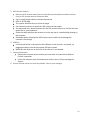
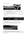
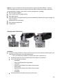
Turn the adjuster back once again in the opposite direction by one-half the total
number of turns to center the dish on the signal beam.
2. Tighten the top elevation rod nut, and then tighten the side elevation bolts. Reconfirm
signal using the push pull method after tightening all elevation bolts.
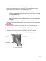
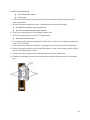
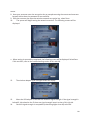
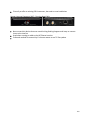
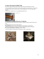
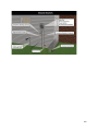
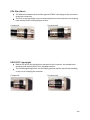
3. With the signal meter still connected, using the azimuth fine-tune cam, fine-tune the
azimuth angle to achieve maximum signal using the following method.
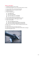
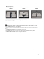
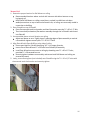
First, loosen the three azimuth plate bolts labeled with a ‘T’ just enough to allow the
two azimuth plates to rotate.
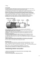
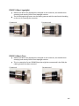
Using the 1/2” wrench slowly turn the cam adjuster clockwise.
Watch the signal meter for value changes.
Rotate the cam clockwise until the highest possible signal is reached, repeat rotations
if necessary.
IMPORTANT: Do not tighten the azimuth fine-tune cam.
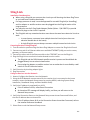
4. Tighten the three azimuth plate bolts labeled with a ‘T’ and reconfirm signal using the push
pull method.
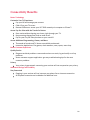
Complete Assembly
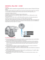
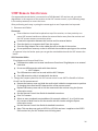
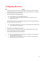
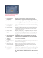
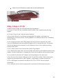
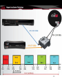
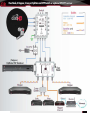
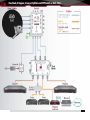
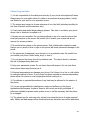
1. Connect the receiver cable(s) to the DPP 1000.4 LNBF PORT 1 (and PORT 2 and PORT 3, as
necessary).
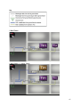
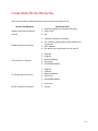
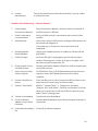
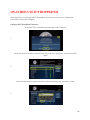
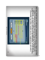
2. Run Check Switch test and confirm 61.5°W, 72.7°W, and 77°W reception.
3. Take a software download, if you didn’t already.
4. Run a second Check Switch test and confirm 61.5ºW, 72.7ºW, and 77° reception.
5. Install additional receiver(s), if necessary.
6. If applicable, connect a second satellite dish to the DPP 1000.4 LNBF’s LNB IN port.
12