1
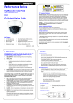
VideoBloX
Cross Point Maxtrix Switch
Quick Start Guide
Document 900.0840 – 09/06 – Rev 1.00
Revisions
Issue
Date
Revisions
1.00
09/06
Initial Release
VideoBloX Quick Start Guide
CONTENTS
1
Purpose . . . . . . . . . . . . . . . . . . . . . . . . . . . . . . . . . . . . . . . . . . . . . . . . . 1
2
Equipment Required . . . . . . . . . . . . . . . . . . . . . . . . . . . . . . . . . . . . . . . . . . 3
Matrix and VideoBloX components .
Accessories (Not included). . . . . .
Configuration PC (laptop or desktop)
Cable and Miscellaneous. . . . . . .
3
.
.
.
.
.
.
.
.
.
.
.
.
.
.
.
.
.
.
.
.
.
.
.
.
.
.
.
.
.
.
.
.
.
.
.
.
.
.
.
.
.
.
.
.
.
.
.
.
.
.
.
.
.
.
.
.
.
.
.
.
.
.
.
.
.
.
.
.
.
.
.
.
.
.
.
.
.
.
.
.
.
.
.
.
.
.
.
.
.
.
.
.
.
.
.
.
.
.
.
.
.
.
.
.
.
.
.
.
.
.
.
.
.
.
.
.
.
.
.
.
.
.
.
.
.
.
.
.
.
.
.
.
.
.
.
.
.
.
.
.
.
.
.
.
.
.
.
.
.
.
.
.
.
.
.
.
.
.
.
.
.
.
.
.
.
.
.
.
.
.
.
.
.
.
.
.
.
.
.
.
.
.
.
.
.
.
.
.
.
.
.
.
.
.
.
.
.
.
.
.
.
.
.
.
.
.
.
.
.
.
.
.
.
.
.
.
.
.
.
.
.
.
.
.
.
.
.
.
.
.
.
.
.
.
.
.
.
.
.
.
.
.
.
.
.
.
.
.
.
.
.
.
.
.
.
.
.
.
.
.
.
.
.
.
.
.
.
.
.
.
.
.
.
.
.
.
.
.
.
.
.
.
.
.
.
.
.
.
.
.
.
.
.
.
.
.
.
.
.
.
.
.
.
.
.
.
.
.
.
.
.
.
.
.
.
.
.
.
.
.
.
.
.
.
.
.
.
.
.
.
.
.
.
.
.
.
.
.
.
.
.
.
.
.
.
.
.
.
.
.
.
.
.
.
.
.
.
.
.
.
.
.
.
.
.
.
.
.
.
.
.
.
.
.
.
.
.
.
.
.
.
.
.
.
.
.
.
.
.
.
3
3
3
4
.
.
.
.
.
.
.
.
.
.
.
.
.
.
.
.
.
.
.
.
.
.
.
.
.
.
.
.
.
.
.
.
.
.
.
.
.
.
.
.
.
.
.
.
.
.
.
.
.
.
.
.
.
.
.
.
.
.
.
.
.
.
.
.
.
.
.
.
.
.
.
.
.
.
.
.
.
.
.
.
.
.
.
.
.
.
.
.
.
.
.
.
.
.
.
.
.
.
.
.
.
.
.
.
.
.
.
.
.
.
.
.
.
.
.
.
.
.
.
.
.
.
.
.
.
.
.
.
.
.
.
.
.
.
.
.
.
.
.
.
.
.
.
.
.
.
.
.
.
.
.
.
.
.
.
.
.
.
.
.
.
.
.
.
.
.
.
.
.
.
.
.
.
.
.
.
.
.
.
.
.
.
.
.
.
.
.
.
.
.
.
.
.
.
.
.
.
.
.
.
.
.
.
.
.
.
.
.
. 5
. 5
. 6
. 6
. 7
. 7
. 8
. 9
. 9
. 9
. 10
. 11
. 11
.
.
.
.
.
.
.
.
.
.
.
.
.
.
.
.
.
.
.
.
.
.
.
.
.
.
.
.
.
.
.
.
.
.
.
.
.
.
.
.
.
.
.
.
.
.
.
.
.
.
.
.
.
.
.
.
.
.
.
.
.
.
.
.
. 13
. 13
. 13
. 14
Configuration with the PC . . . . . . . . . . . . . . . . . . . . . . . . . . . . . . . . . . . . . . 15
Connect the PC to the VideoBloX CPU . . . . . . . . . . . . . . . . .
Install the VideoBloX Configuration Software on the Configuration PC .
Start the VideoBloX Configuration Program . . . . . . . . . . . . . . .
Configure a User . . . . . . . . . . . . . . . . . . . . . . . . . . . . .
Configure the Video Inputs . . . . . . . . . . . . . . . . . . . . . . . .
6
.
.
.
.
Video Switching . . . . . . . . . . . . . . . . . . . . . . . . . . . . . . . . . . . . . . . . . . . . 13
Log-On to Keyboard . . . . . . .
Switching Cameras and Monitors
Select Monitor. . . . . .
Select Camera . . . . .
5
.
.
.
.
Component Connections . . . . . . . . . . . . . . . . . . . . . . . . . . . . . . . . . . . . . . . . 5
Matrix Chassis . . . . . . . . . . . . . . . .
Cameras and Dome . . . . . . . . . . . . .
Monitors . . . . . . . . . . . . . . . . . . .
How to Use the Diagnostic Monitor
Connect the Keyboard . . . . . . . . . . . .
Installation. . . . . . . . . . . . . .
Configuring the Keyboard . . . . .
Connecting to the High Speed Dome . . . .
Cable Connection. . . . . . . . . .
Address the Dome . . . . . . . . .
Address the PIT . . . . . . . . . . .
Installing the Alarm Termination Box (ATB) .
Installation. . . . . . . . . . . . . .
4
.
.
.
.
.
.
.
.
.
.
.
.
.
.
.
.
.
.
.
.
.
.
.
.
.
.
.
.
.
.
.
.
.
.
.
.
.
.
.
.
.
.
.
.
.
.
.
.
.
.
.
.
.
.
.
.
.
.
.
.
.
.
.
.
.
.
.
.
.
.
.
.
.
.
.
.
.
.
.
.
.
.
.
.
. 15
. 16
. 17
. 19
. 21
Controlling the Dome . . . . . . . . . . . . . . . . . . . . . . . . . . . . . . . . . . . . . . . . . 23
Dome Presets. . . . . . . . . . . . . . . . . . . . . . . . . . . . . . . . . . . . . . . . . . . . . . . . 24
To Store Presets . . . . . . . . . . . . . . . . . . . . . . . . . . . . . . . . . . . . . . . . . 24
To Recall Presets . . . . . . . . . . . . . . . . . . . . . . . . . . . . . . . . . . . . . . . . . 24
7
Simple Alarm Sequence Configuration . . . . . . . . . . . . . . . . . . . . . . . . . . . . . . . 25
Configuring the Alarm Inputs . . . . . . . . . . . . . . . . . . . . . . . . . . . . . . . . . . . . . . . . 25
Rev 1.00
i
Document 900.0840
09/06
CONTENTS
Programming Sequence #1 . . . . . . . . . . . . . . . . . . . . . . . . . . . . . . . . . . . . . . . . 27
Programming Sequence #2 . . . . . . . . . . . . . . . . . . . . . . . . . . . . . . . . . . . . . . . . 28
Testing . . . . . . . . . . . . . . . . . . . . . . . . . . . . . . . . . . . . . . . . . . . . . . . . . . . 29
Rev 1.00
ii
Document 900.0840
09/06
VideoBloX Quick Start Guide
FIGURES
Figure 1
Connecting Cameras to the Video Input Module . . . . . . . . . . . . . . . . . . . . . . . . 5
Figure 2
Connecting Monitors to the Video Output Module . . . . . . . . . . . . . . . . . . . . . . . 6
Figure 3
Connecting the Diagnostic Monitor to the CPU Module . . . . . . . . . . . . . . . . . . . . 6
Figure 4
Connecting the HEGS5BLX Keyboard . . . . . . . . . . . . . . . . . . . . . . . . . . . . . 7
Figure 5
Connecting an HVBPIT44 and High Speed Dome . . . . . . . . . . . . . . . . . . . . . . . 9
Figure 6
Alarm Terminal Block (ATB) Connections . . . . . . . . . . . . . . . . . . . . . . . . . . . 11
Rev 1.00
iii
Document 900.0840
09/06
FIGURES
Rev 1.00
iv
Document 900.0840
09/06
1
Purpose
The purpose of this guide is to instruct a user how to install and operate a basic VideoBloX
Cross Point Matrix Switching system. The following instructions are included.
1.
Rev 1.0
How to install a basic VideoBloX system with:
a.
Keyboard
b.
Static Cameras
c.
Monitors
d.
High Speed Dome
e.
Alarm Input/Output Termination Board
2.
How to switch cameras to monitors
3.
How to control a high speed dome
4.
How to create a Sequence driven by an Alarm Input
1
Document 900.0840
09/06
Purpose
Rev 1.0
2
Document 900.0840
09/06
2
Equipment Required
Matrix and VideoBloX components
•
•
•
•
Matrix Chassis (4U, 8U or 12U) configured with CPU, Video Input Module and Video
Output Module (with titles)
Alarm Terminal Panel (shipped with CPU)
HVBPIT44 PIT for dome control
HEGS5BLX Keyboard with HVB232422 Converter (HEGS5BLX-KT)
Accessories (Not included)
•
•
•
2) Video Monitors
2) Static Cameras
1) High Speed Dome (Orbiter, RapidDome, or HD6)
Configuration PC (laptop or desktop)
•
Rev 1.0
Available COM port
3
Document 900.0840
09/06
Equipment Required
Cable and Miscellaneous
•
•
•
•
•
•
•
•
•
Coaxial cables from Cameras to Video Input Module.
Coaxial cables from Monitors to Video Output Module.
Power cable from cameras to 24VAC Power Supply
RS232 Cable - from COM port on PC to VideoBloX CPU (9-pin Female connector to
9-pin Female connector, included)
Build an RS232 cable with fly leads on one end and a male DB9 connector on the
other end. This cable is for connection between the HEGS5BLX terminal block and
the female DB9 on the RS232/RS422 converter
Modify one of the supplied RS422 cables with male DB9 connectors on both ends to
fly-leads on one end and male DB9 connector on the other end. Cut one of the DB9
connectors off and strip the wires back 1/4”. This cable is connected between the
terminal strip on the RS232/RS422 converter terminal strip and the VideoBloX CPU
RS422 master female DB9 connector.
Flat 6x6 cable (supplied with the HEGS5BLX) for connection between the HEGS5BLX
and the terminal block (supplied with the HEGS5BLX).
Special Cable from the PIT to the Dome. The output from the PIT is RS422. Build a
2-wire cable lead using CAT5 or similar type. Solder the wires to pin 1 and 2 of a 9-Pin
Male D-plug. Connect the plug to the PIT and the end of the wires to the DATA inputs
of the dome.
Standard PC Power cable (IEC)
Note
Rev 1.0
All coaxial cable must have a nominal impedance of 75 ohms.
The RS422 cable should be 8-core twisted-pair with a shunt
capacitance of 16 pF/ft (CAT5).
4
Document 900.0840
09/06
3
Component Connections
Matrix Chassis
The VideoBloX chassis is shipped with a power cable without a plug. This is to
accommodate the various methods of power connectivity. Connect the wires on the
power cable to the appropriate power source.
This installation assumes the power requirements are 110 VAC. Using a standard PC
power cable, connect the matrix chassis to a 110 VAC supply.
Note
Do not connect Keyboard, PIT and Alarms at this time.
Cameras and Dome
1.
Make sure the Dome is at address #1 and is connected to Input #1 on the Video
Input Module.
2.
Provide power to the static cameras and connect the coaxial cables to Inputs #2
and 3 on the Video Input Module.
Figure 1
Connecting Cameras to the Video Input Module
Camera #3
Rev 1.0
5
Camera #2
Dome
Document 900.0840
09/06
Component Connections
Monitors
1.
Provide power to the monitors.
2.
Using coaxial cable, connect one monitor to Output #1 on the Video Output Module.
Figure 2
Connecting Monitors to the Video Output Module
Connect
Monitor
#1
3.
Using coaxial cable, connect the second monitor (diagnostic monitor) to the CPU
video output on the CPU module. This monitor is used to edit /view the current
settings of the system. It should be displaying a [0] on the top center of the screen. If
not, then make sure the chassis and the monitor are powered and the monitor is
connected to the BNC connector on the CPU.
Figure 3
Connecting the Diagnostic Monitor to the CPU Module
Connect
Monitor
#2
CPU
Video
How to Use the Diagnostic Monitor
There are four small pushbuttons on the faceplate of the CPU Module. These are used to
step through the display screens in the diagnostic mode.
The pushbutton on the far right (down arrow) pages through the screens. Press this button
to go from page 1 to 2 and so forth.
The pushbutton second from the right (up arrow) moves through the pages in the opposite
direction.
Use the right pushbutton to go to page [2] - "Communications"
Note
Rev 1.0
Make a note of the Baud Rate for Master (Keyboards and PITs) port and of the
PC/Slave (connection to PC).
6
Document 900.0840
09/06
VideoBloX Quick Start Guide
Connect the Keyboard
Installation
1.
Locate the HEGS5BLX controller, terminal block, 6x6 flat cable, power supply
(included with controller), HVB232422 converter, and power supply (included with
HVB232422 converter).
Figure 4
Connecting the HEGS5BLX Keyboard
HVB232422
RS232/RS422 Converter
TERMINAL
BLOCK
RS232 RX
Power Supply
12 VDC 2A
+12V
GND
Female DB9
RS232 TXD
Pin 5, GND
Pin 3, RXD
Pin 2, TXD
1
5
9
6
RJ11 Jack
TX+
TX-
RX+
RX-
VideoBloX CPU Module
RS422 Master
Female DB9
Pin 3, RX+
Pin 4, RXPin 2, TX+
Pin 1, TX-
+V
Gnd
-V
Pin 5, GND
6x6 Flat
Cable
- 12-30 VDC Power Supply
+ Part #849193-0089
RJ11 Jack
HEGS5BLX KEYBOARD
Rev 1.0
2.
Connect the 6x6 flat cable between the RJ11 jack on the controller and the RJ11 jack
on the terminal block.
3.
Connect the RS232 cable with fly leads on one end and a male DB9 connector on the
other end.
a.
Connect the fly leads to the terminal block.
b.
Connect the male DB9 connector to the female DB9 connector on the
RS232/RS422 converter.
7
Document 900.0840
09/06
Component Connections
4.
Locate the 9-pin D-type Male to 9-Pin D-type Male RS422 cable supplied with the
matrix chassis. Cut off one of the DB9 connectors and strip the wires back for
connection to the terminal strip on the RS232/RS422 converter. Connect the other
DB9 connector to the the RS422 Master female port on the VideoBloX CPU module.
This port is the third from the left port when viewing the chassis from behind.
5.
Connect the power supply provided with the HEGS5BLX keyboard to the terminal
block.
6.
Connect the power supply provided with the HVB232422 Converter to the power
terminal strip on the converter.
The keyboard should immediately power-up and display its booting screens then the
address and baud rate settings. The baud rate must be the same as that shown in the
Diagnostic Screen (section 9) for "Master" (default 19,200 Baud) and the keyboard address
should be 1. To change the baud rate speed and address, perform the procedure for
configuring the keyboard.
Configuring the Keyboard
Rev 1.0
1.
Power down the unit and power it back up.
2.
Press the middle soft key below the LCD after
the controller counts down, while the application
screen shown to the right is displayed.
The address selection screen is displayed.
HEGS5BLX
030106
922.0255 Rev. A
3.
Press Enter to accept the current address shown
in parenthesis or enter a new address using the numeric keys and press Enter. The
Tilt configuration is displayed.
4.
Press 1 for normal tilt operation. Press 2 to reverse the tilt operation; that is the tilt up
command sends a tilt down command to the PTZ and the tilt down command sends a
tilt up command to the PTZ. When the desired selection is displayed, press Enter.
The baud rate configuration is displayed.
5.
Press the + and - keys to scroll through the available baud rates, 1200, 9600, 19200,
and 57600. When the desired baud rate is displayed, press Enter. The default baud
rate is 19200. The controller returns to the Login screen.
8
Document 900.0840
09/06
VideoBloX Quick Start Guide
Connecting to the High Speed Dome
The Orbiter, RapidDome, or HD6 domes connect to the system via an HVBPIT44 Protocol
Interface Translator (PIT). This device converts the native protocol of VideoBloX to the
protocol of the connected dome.
Cable Connection
1.
Using the 9-pin Male to 9-Pin Male (pin to pin) connect the Slave Channel of the PIT to
the RS422 Master port on the VideoBloX CPU module. This is the fourth connector
from the left port when viewing the chassis from behind.
2.
Using the RS422 cable with 9-Pin male connector on one end and fly leads" on Pins 1
and 2, connect Pin #1 (TXD -) to the Data (-) on the Dome. Connect Pin #2 (TXD +) to
the Data (+) on the Dome.
Figure 5
Connecting an HVBPIT44 and High Speed Dome
1
Pin 1 (TXD-) to Data Pin 2 (TXD+) to Data+
HVBPIT44
2 3 4 56 7 8
1 23 45 678
1
23 456 78
12 34 5678
RS422
Master
RS422
Slave
DB9 Male to DB9 Male
HVBCPU
RS422
Master
Address the Dome
Rev 1.0
1.
Set the Dome to address #1 (see Manual for Dome )
2.
Set the Dome for VCL or Maxpro mode protocol (see Manual for Dome)
9
Document 900.0840
09/06
Component Connections
Address the PIT
VCL Settings
Switch #1 - Position 2 "On" all others "off"
Switch #2 - All positions "off"
Switch #3 - Position #1 and #8 - "On", all others "off"
Maxpro Mode Settings
Switch #1 - Positions 1, 2, and 3 “On”; position 4 “off”
Switch #2 - all positions off for broadcast mode
Switch #3, position 1 “on” for MAX 100/Diamond protocol
Switch #3, position 7 off; position 8 on (Slave baud rate of 19.2KB). Must be set the same
as Master port baud rate on CPU.
Switch #2, positions 5,6,7 set to off (PTZ Address 1-8).
Switch #3 positions 5, 6 set to off.
Rev 1.0
10
Document 900.0840
09/06
VideoBloX Quick Start Guide
Installing the Alarm Termination Box (ATB)
The ATB is shipped with the VideoBloX system and consists of a stainless steel box with a
ribbon cable.
•
•
•
Support for 32 Alarm Inputs - potential free (dry) contact
Support for 4 Form C Relays
Removable Terminal Blocks
1.
Connect the ATB to the VideoBloX CPU using the ribbon cable supplied.
2.
Connect a toggle switch or other alarm device to activate the alarm signal to Input #1
of ATB.
3.
Connect an output device (lamp or sounder) to the Common/Normally Open of
Output #1 and the appropriate power supply.
Installation
Figure 6
Alarm Terminal Block (ATB) Connections
Ribbon Connector
to CPU
External
Power Supply
Controlled
Device
ALARMTERMINATIONBOX
S
2
3
4
5
6
7
8
9
10
11
12
13
14
15
17
18
19
20
21
22
23
24
25
26
27
28
29
30
31
32
Typical Input
NO/NC Dry Contact
C
NC
NO
1
OUT2
C
NC
NO
Relay Ratings
1A @ 30 VDC
0.5A @ 24 VAC
C
NC
NO
OUT3
C
NC
NO
OUT4
Alarm Inputs are
pulled to 5 VDC by
10K resistor.
RelayOutput s
Rev 1.0
11
AlarmInput s
Document 900.0840
09/06
Component Connections
Rev 1.0
12
Document 900.0840
09/06
4
Video Switching
On start up, the system will require the operator to LogIn at the keyboard before
controlling any of the devices. This requires a password, which is set-up in the PC
Configuration program.
Log-On to Keyboard
1.
Press the Log In/Log Out key
2.
Enter the Password (default is "0")
3.
Press Enter.
Switching Cameras and Monitors
Note
Remove monitor #2 connection from the CPU BNC output and connect that
to Output #2 of Output Module.
There are mode keys (Camera, Monitor, DVR, and Sequence) on the HEGS5BLX
Keyboard.
Select Monitor
Press the Monitor Key (the system is now in Monitor mode).
Rev 1.0
13
Document 900.0840
09/06
Video Switching
Press a number key and then Enter to select the monitor output you desire. For this
example, press 1 then Enter.
Note
You can use the Next and Previous keys to scroll through the available
monitors.
Select Camera
Press the Camera key (the system is now in Camera mode)
The system now switches any selected camera to the monitor (#1) selected above.
Press a number key and Enter to select a camera.
Note
Rev 1.0
You can use the Next and Previous keys to scroll through the available
cameras.
14
Document 900.0840
09/06
5
Configuration with the PC
Connect the PC to the VideoBloX CPU
Using the 9-pin Female to 9-Pin Female (pin to pin) connect the selected COM port of the
Configuration PC to the RS232 Slave port on the VideoBloX CPU. This is the furthest left
port when viewing the chassis from behind.
PC with Configuration Software
Com
Port
9-Pin
Male to Male
Cable
RS232
Slave
Rev 1.0
15
Document 900.0840
09/06
Configuration with the PC
Install the VideoBloX Configuration Software on the
Configuration PC
Note
Rev 1.0
The Configuration Software is distributed on a CD-ROM that shipped with the
CPU/Chassis.
1.
Insert the VideoBloX CD in the PC CD-Rom drive.
2.
From Windows Start Menu, click on Run
3.
Click on the Browse button and locate your CD-Rom drive.
4.
Locate the VBLoxCFG folder on the CD.
5.
Double click on SETUP.EXE.
6.
Follow the on-screen prompts to install the default configuration.
16
Document 900.0840
09/06
VideoBloX Quick Start Guide
Start the VideoBloX Configuration Program
Rev 1.0
1.
From the Windows Start menu, click on Programs, then VBloXCFG, and then vbloxcfg
2.
"Click" on the Configure button (Configure, Synch Time and Diagnostics).
17
Document 900.0840
09/06
Configuration with the PC
3.
The Main Configuration screen is shown. Note the Red or Green Window - this is the
communications "handshake".
Communications
Handshake
Communications
Tab
a.
If the window is Green - then you have successfully connected.
b.
If the window is Red then adjust the baud rate.
1.
Select the Communications tab and select the appropriate communication
port on your PC.
2.
Select the Com Port on the PC where the CPU module in the matrix chassis
is connected.
3.
Configure the baud rate so the PC Com Port and the CPU are the same. The
default is 19.2K.
Note
Rev 1.0
If necessary, refer to the Communications Page on the diagnostic monitor to
view the CPU baud rate setting.
4.
Configure the Stop Bits to (1).
5.
The window should immediately change to Green. If it does not then check
your cable.
18
Document 900.0840
09/06
VideoBloX Quick Start Guide
Configure a User
From the Configuration Program, click on the Users tab.
Configure User Number 1:
1.
Make sure Enabled is checked
2.
Make sure expiry date is in the future
3.
Click on Set Password.
The default password for User 1 is 0 (zero). You can leave it at 0 or create a new one.
Caution
4.
Rev 1.0
Make sure you remember the new password if you change it.
Close the dialog box.
19
Document 900.0840
09/06
Configuration with the PC
5.
6.
7.
8.
Rev 1.0
Next, click on the Cameras button in the access portion of the screen.
a.
Make sure they are all checked Green. If not, click on User 1 (top left) to give User
1 access to all cameras.
b.
Click O.K.
Click on the Monitors button in the Access section.
a.
Make sure they are all checked Green. If not, click on User 1 (top left) to give User
1 access to all monitors.
b.
Click OK
Click on the Keyboards button in the Access section.
a.
Make sure all available Functions are checked. If not, click on User 1 (top left) to
give User 1 access to all functions.
b.
Click OK.
Click on download to send the user configuration to the CPU.
20
Document 900.0840
09/06
VideoBloX Quick Start Guide
Configure the Video Inputs
From the Configuration Program, click on the "Inputs" tab.
Configure Input Number #1 (the video input where the dome is connected.
Rev 1.0
1.
Select the Type of Camera as PTZ
2.
Configure the Pan/Tilt/Zoom address to match the dome address (#1)
3.
Click on Download to send configuration to the CPU.
21
Document 900.0840
09/06
Configuration with the PC
Rev 1.0
22
Document 900.0840
09/06
6
Controlling the Dome
Now that the dome is connected and configured, it can be controlled from the keyboard.
Perform the following steps to select and control the dome.
1.
Press Camera to place the controller in Camera Mode
2.
Enter the dome address (1) and press Enter. Camera #1 is switched to the monitor
selected on the keyboard.
3.
Use the joystick to move the dome.
4.
Zoom by twisting the joystick
When in the Camera Mode, the keyboard enables keys for Dome Control and Adjustment.
•
•
•
•
•
•
Zoom + to zoom In
Zoom - to zoom out
Focus + to control the focus
Focus - to control the focus
Iris + to control the iris
Iris - to control the iris
Note
Rev 1.0
When both the ( + )and ( - ) keys for a function are pressed simultaneously,
the camera goes into automatic mode for that function. For example, press
Iris + and Iris - simultaneously for automatic iris mode.
23
Document 900.0840
09/06
Controlling the Dome
Dome Presets
The Dome can be set up for Preset views.
To Store Presets
1.
Move the dome to the selected view with the joystick.
2.
Press the Alt and the Preset/Save key simultaneously.
3.
Enter a number for the preset.
4.
Press the Enter key.
5.
Repeat for all the presets.
To Recall Presets
1.
Press the Preset/Save key.
2.
Enter a number corresponding to the required preset.
3.
Press the Enter key.
The dome moves to the programmed preset position.
Rev 1.0
24
Document 900.0840
09/06
7
Simple Alarm Sequence Configuration
The following example configures a simple sequence (event/action).
The first event turns relay #1 on when there is a contact closure on Alarm Input #1.
The second event turns Relay #1 off when there is a Contact Open on Alarm Input #1.
Configuring the Alarm Inputs
Rev 1.0
1.
From the Configuration Program, click on the Alarms tab.
2.
Click on the Alarm Inputs button.
25
Document 900.0840
09/06
Simple Alarm Sequence Configuration
3.
Confirm that alarms 1 to 16 and 17 to 32 are marked as "Local". These are the Alarm
Inputs on the Alarm Terminal Box.
Set to
Local
4.
Close this window.
5.
Select Alarm #1 and "check" the Enable box.
6.
Go to the Contact Open area and "check" the Enable box
7.
Select Sequence #2
8.
Go to the Contact Close area and "check" the Enable box
9.
Select Sequence #1
10. Click on Download to send configuration to the CPU.
Rev 1.0
26
Document 900.0840
09/06
VideoBloX Quick Start Guide
Programming Sequence #1
From the Configuration Program, click on the Sequence tab,
Rev 1.0
1.
Select Sequence #1
2.
Click on the Edit Sequence button. An edit window opens with the End command on
the first line.
3.
Click on the "+" button to insert a new line.
4.
Click on the command field in the new line.
27
Document 900.0840
09/06
Simple Alarm Sequence Configuration
5.
Click on the arrow in the command field. A drop down box appears.
6.
A selection of the available commands appears. Scroll down and select "OUTPUT".
Note
Help information is displayed for each command and its associated
parameters at the bottom of the screen
7.
Enter the Output in the Parm (parameter) #1 column
8.
Enter the Output State = 1 in the Parm #2 column. State 1 - is On; State 0 - is Off
9.
Click on Download to send configuration to the CPU.
Programming Sequence #2
From the Configuration Program, click on the Sequence tab
Rev 1.0
1.
Perform steps 1-7 of Programming Sequence #1.
2.
Enter the Output in the Parm (parameter) #1 column
3.
Enter the Output State = 0 in the Parm #2 column; State 1 - is On; State 0 - is Off
4.
Click on Download to send configuration to the CPU.
28
Document 900.0840
09/06
VideoBloX Quick Start Guide
Testing
“Close" Alarm Input #1 and observe the Relay "On"
"Open" Alarm Input #1 and observe the Relay "Off"
Rev 1.0
29
Document 900.0840
09/06
Simple Alarm Sequence Configuration
Rev 1.0
30
Document 900.0840
09/06
Honeywell Video Systems (Head Office)
2700 Blankenbaker Pkwy, Suite 150
Louisville, KY 40299, USA
www.honeywellvideo.com
℡ +1.800.796.2288
Honeywell Video Systems Northern Europe
Netwerk 121
1446 WV Purmerend, The Netherlands
www.SecurityHouse.nl
℡ +31.299.410.200
Honeywell Security Australia Pty Ltd.
Unit 5, Riverside Centre, 24-28 River Road West
Parramatta, NSW 2150, Australia
www.ademco.com.au
℡ +61.2.8837.9300
Honeywell Video Systems UK Ltd.
Aston Fields Road, Whitehouse Ind Est
Runcorn, Cheshire, WA7 3DL, UK
www.honeywellvideo.com
℡ +0844 8000 235
Honeywell Security Asia Pacific
33/F Tower A, City Center, 100 Zun Yi Road
Shanghai 200051, China
www.security.honeywell.com/cn
℡ +86 21.2527.4568
Honeywell Security South Africa
Unit 6 Galaxy Park, 17 Galaxy Avenue
Linbro Park, P.O. Box 59904
2100 Kengray, Johannesburg, South Africa
www.honeywell.co.za
℡ +27.11.574.2500
Honeywell Security Asia
Flat A, 16/F, CDW Building, 388 Castle Peak Road
Tsuen Wan, N.T., Hong Kong
www.security.honeywell.com/hk
℡ +852.2405.2323
Honeywell Security France
Parc Gutenberg, 8, Voie La Cardon
91120, Palaiseau, France
www.honeywell.com/security/fr
℡ +33.01.64.53.80.40
Honeywell Security Italia SpA
Via Treviso 2 / 4
31020 San Vendemiano
Treviso, Italy
www.honeywell.com/security/it
℡ +39.04.38.36.51
Honeywell Security España
Mijancas 1. 3a Planta
P.Ind. Las Mercedes
28022 Madrid, Spain
www.security.honeywell.com/es
℡ +34.902. 667.800
Honeywell Security Deutschland
Johannes-Mauthe-Straße 14
D-72458 Albstadt, Germany
www.honeywell.com/security/de
℡ +49.74 31.8 01.0
Honeywell Security Poland
Chmielewskiego 22a, 70-028
Szczecin, Polska
www.ultrak.pl
℡ +48.91.485.40.60
Honeywell Security Czech Republic
Havránkova 33, Brno
Dolní Heršpice, 619 00, Czech Republic
www.olympo.cz
℡ +420.543.558.111
Honeywell Security Slovakia Republic
Vajnorská 142, 83104 Bratislava
Slovakia
www.olympo.sk
℡ +421.2.444.54.660
www.honeywellvideo.com
+1.800.796.CCTV (North America only)
[email protected]
Document 900.0840 09/06 Rev 1.00
© 2006 Honeywell International Inc. All rights reserved. No part of this publication may be reproduced by any means without written
permission from Honeywell Video Systems. The information in this publication is believed to be accurate in all respects. However,
Honeywell Video Systems cannot assume responsibility for any consequences resulting from the use thereof. The information
contained herein is subject to change without notice. Revisions or new editions to this publication may be issued to incorporate such
changes.