1
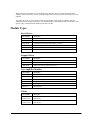
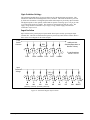
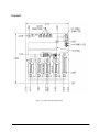
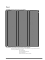
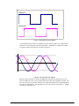
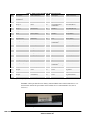
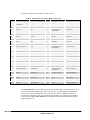
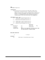
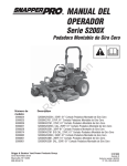
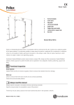
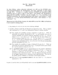
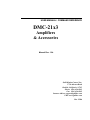
AECOM2
GND
JP2
AEC2
Pin 1
GND
JP1
PIN 1
RPAE2 (820 Ohm)
+5 V
RPAE1 (470 Ohm)
+12 V
Amp Enable Output to Drive
AECOM1
Pin 1
of socket
+5 V
Socket U1
TTL level Amp
Enable signal
from controller
(SH = 5V, MO = 0V)
+12 V
Amplifier Enable Circuit
Sourcing Output Configuration
(Pin 1 of PS2505 in Pin 1 of Socket U1)
AEC1
TTL level Amp
Enable signal
from controller
(SH = 5V, MO = 0V)
AECOM2
GND
+5 V
+12 V
PS2505-4
5V or GND
JP2
AEC2
Figure 9 Amplifier Enable Circuit Sourcing Output Configuration
Sourcing Configuration (pin1 of PS2505 chip in pin1 of socket U1)
Logic State
JP1
JP2
RPAE1
(square pin next to RPAE1 label is 5V)
5V, HAEN
GND - AEC1
5V - AEC2
Dot on R-pack opposite RPAE1 label
5V, LAEN
GND - AEC1
5V - AEC2
Dot on R-pack next to RPAE1 label
12V, HAEN
GND - AEC1
+12V - AEC2
Dot on R-pack opposite RPAE1 label
12V, LAEN
GND - AEC1
+12V - AEC2
Dot on R-pack next to RPAE1 label
Isolated 24V, HAEN
AECOM1 - AEC1
AECOM2 - AEC2
Dot on R-pack opposite RPAE1 label
Isolated 24V, LAEN
AECOM1 - AEC1
AECOM2 - AEC2
Dot on R-pack next to RPAE1 label
For 24V isolated enable, tie +24V of external power supply to AECOM2 at any axis D-sub, tie common return to
AECOM1. Replace RPAE2 with a 4.7 kΩ resistor pack. AECOM1 and AECOM2 are located on any 15-pin axis D-subs
(JX, JY, JZ, or JW). All pins labeled AECOM1 are connected. All pins Labeled AECOM2 are connected.
DMC-21x3 Accessories
Chapter 4 ICM-20105• 21