1
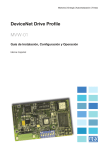
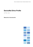
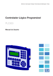
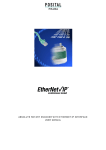
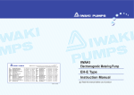
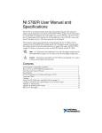
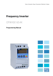
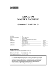
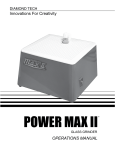
Motors | Energy | Automation | Coatings DeviceNet Drive Profile MVW-01 Installation, Configuration and Operation Guide Language: English Index 1 DEVICENET DRIVE PROFILE....................................................................5 1.1 DEVICENET DRIVE PROFILE PARAMETER LIST............................................. 5 1.2 INSTALLATION OF THE FIELDBUS KIT............................................................. 6 1.3 INTRODUCTION TO THE DEVICENET............................................................... 6 1.3.1 Cable and Connector................................................................................. 6 1.3.2 Line Termination........................................................................................ 7 1.3.3 Baud rate and Node Address................................................................... 7 1.3.4 Signaling LEDs........................................................................................... 7 1.3.5 Configuration File (EDS File)..................................................................... 8 1.4 INVERTER PARAMETER SETTING.................................................................... 8 1.5 I/O DATA................................................................................................................ 9 1.5.1 Data Content for Instances 20 / 70.......................................................... 9 1.5.1.1 Write Words (instance 20).....................................................................10 1.5.1.2 Read Words (instance 70).....................................................................10 1.5.2 Data Content for Instances 21 / 71.........................................................11 1.5.2.1 Write Words (instance 21).....................................................................11 1.5.2.2 Read Words (instance 71).....................................................................12 1.5.2.3 Speed Reference for Instances 20 and 21..........................................13 1.5.2.4 Motor Speed for Instances 70 and 71.................................................14 1.5.3 Data Content for Instances 100 / 101.....................................................14 1.5.3.1 Write Words (instance 100)...................................................................14 1.5.3.2 Read Words (instance 101)...................................................................15 1.5.4 Data Content for Instances 102 / 103.....................................................15 1.5.4.1 Selection of the Number of Words for the I/O area...........................15 1.5.4.2 Parameter Selection for the I/O area.................................................15 1.5.4.3 Specific Parameters for the I/O area..................................................16 1.5.4.3.1 P370: WEG Logic Command..............................................................16 1.5.4.3.2 P371: Speed Reference ....................................................................17 1.5.4.3.3 P372: Command for the Digital Output............................................17 1.5.4.3.4 P373: WEG Logic Status....................................................................18 1.5.4.3.5 P374: Motor Speed..............................................................................18 1.5.4.3.6 P375: Status of the digital inputs......................................................19 1.5.4.4 Software Error........................................................................................19 1.6 VARIABLES SCAN TIME.....................................................................................19 1.7 COMMUNICATION ERROR............................................................................... 20 1.7.1 E29: Fieldbus Communication is inactive............................................. 20 1.7.2 E30: Fieldbus board inactive................................................................... 20 1.8 OBJECT CLASSES FOR THE DEVICENET NETWORK.................................. 21 1.8.1 Identity Object, Class 01hex. .................................................................... 21 1.8.2 Message Router Object, Class 02 hex..................................................... 21 1.8.3 DeviceNet Object, Class 03 hex................................................................ 21 1.8.4 Assembly Object, Class 04 hex................................................................. 22 1.8.5 DeviceNet Connection Object, Class 05 hex........................................... 23 1.8.6 Acknowledge Handler Object, Class 2Bhex........................................... 26 1.8.7 Motor Data Object, Class 28 hex. ............................................................. 26 1.8.8 Control Supervisor Object, Class 29 hex................................................. 27 1.8.9 AC/DC Drive Object, Class 2Ahex............................................................ 28 1.8.10 Vendor Specific Object, Class 90 hex..................................................... 28 DeviceNet Drive Profile MVW-01 Guide DEVICENET DRIVE PROFILE MVW-01 GUIDE 1 DEVICENET DRIVE PROFILE It was developed with the purpose of making available in the product a DeviceNet communication interface with the following characteristics: Enabling the inverter parameter setting through the network and giving direct access to the parameters with messages sent by the master. Following the standard for the Device Profile for AC and DC Drives, specified by the ODVA (Open DeviceNet Vendor Association), which defines a common object set for drives that operate in DeviceNet network. This guide gives a general overview about the DeviceNet operation, showing mainly the parameter setting and the inverter operation on this network. Detailed protocol description can be gotten from ODVA. 1.1 DEVICENET DRIVE PROFILE PARAMETER LIST Parameter Description P309 Fieldbus P340 I/O Instances P348 P349 P350 P351 P352 P353 P354 P355 P356 P357 P358 P359 P360 P361 P362 P363 P364 P365 P366 Write Parameter #1 Write Parameter #2 Write Parameter #3 Write Parameter #4 Read Parameter #1 Read Parameter #2 Read Parameter #3 Read Parameter #4 Write Parameter #5 Write Parameter #6 Write Parameter #7 Write Parameter #8 Write Parameter #9 Read Parameter #5 Read Parameter #6 Read Parameter #7 Read Parameter #8 Read Parameter #9 Number of IO words Adjustable Range 0 to 10 10 = DeviceNet Drive Profile 0 = 20 / 70 1 = 21 / 71 2 = 100 / 101 3 = 102 / 103 0 to 999 0 to 999 0 to 999 0 to 999 0 to 999 0 to 999 0 to 999 0 to 999 0 to 999 0 to 999 0 to 999 0 to 999 0 to 999 0 to 999 0 to 999 0 to 999 0 to 999 0 to 999 1 to 9 Factory Setting 0 = Inactive 0 = 20 / 70 370 371 372 0 373 374 375 0 0 0 0 0 0 0 0 0 0 0 2 MVW-01 | 5 DeviceNet Drive Profile MVW-01 Guide 1.2 INSTALLATION OF THE FIELDBUS KIT For DeviceNet communication, a KFB-DD kit containing: DeviceNet Drive Profile communication board; Cable with connector for line connection; EDS network configuration file; DeviceNet Drive Profile guide. For kit installation (when the kit is supplied separately), refer to the item 8.4.1 in the MVW-01 Frequency Inverter Manual – Installation of the Fieldbus kit, where you can find all installation procedures. 1.3 INTRODUCTION TO THE DEVICENET The DeviceNet communication is used for industrial automation, mainly for the control of valves, sensors, input/output units and automation equipment. The DeviceNet communication link is base on a CAN communication protocol (Controller Area Network). figure 1.1 gives a general view of a DeviceNet. Tap Terminator Terminator Trunk Line Node Node Drop Line Node Node Node Node Node Node Node Node Node Node Figure 1.1: DeviceNet Network 1.3.1 Cable and Connector The DeviceNet network uses a shielded twisted pair copper cable. One pair makes the 24 Vdc power supply to the different nodes and the other pair is used for the communication signal. An example of connector for the MVW-01, together with the wire color outline used for the connection, is presented in the figure 1.2: 1 Black Blue Shield White Red 2 3 4 5 1 2 3 4 5 Black Blue Shield White Red Figure 1.2: Connector for the DeviceNet network 6 | MVW-01 VCANL SHIELD CANH V+ DeviceNet Drive Profile MVW-01 Guide 1.3.2 Line Termination To avoid signal reflection, the initial and the end points of the network must be terminated with the characteristic impedance. Thus a 120 ohms/0,5 W resistor must be connected between the pins 2 and 4 of the Fieldbus connector. 1.3.3 Baud rate and Node Address There are three different baud rates for the DeviceNet: 125 k, 250 k or 500 kbits/s. Choose one of these baud rates by setting the DIP switch on the communication board. The node address is selected by means of the six DIP switches on the electronic board, permitting the addressing from 0 to 63. Baud rate Address 1 ON 0 1 2 3 4 5 6 7 8 Baud rate [bits/s] DIPs 1 and 2 125 k 00 250 k 01 500 k 10 Reserved 11 Address 0 1 2 ... 61 62 63 DIP3 to DIP8 000000 000001 000010 .... 111101 111110 111111 Figure 1.3: Address Configuration and Baud rate NOTE! The Baud rate and the address of the inverter on the network are only updated when inverter is powered up. 1.3.4 Signaling LEDs The communication board has four signaling LEDs with following functions for the network diagnostics: Host Communication Status Network Status Reserved Module Network Status Figure 1.4: LEDs for status indication of the Communication board MVW-01 | 7 DeviceNet Drive Profile MVW-01 Guide Table 1.1: Signaling of the communication board status LEDs LED Color Green Host Communication Status Red Red flashing Network Status Module Network Status Off Green Red Green flashing Red flashing Off Red Green Red flashing Description Data transfer between board - inverter OK Data transfer fault between board - inverter OK (permanent) Data transfer fault between board - inverter (temporary) Without supply/off line Link operating, connected Critical fault at link On line not connected Time out of the connection Without supply Fault not correctable Operational board Small fault 1.3.5 Configuration File (EDS File) Each element of a DeviceNet network is associated to an EDS file which has all information about the element. This file is used by the configuration program during network configuration. Use the file with the extension .EDS supplied with the Fieldbus kit. NOTE! For this firmware version, together with the communication board you can program the master communication with two different connection types: Polled; or Change of State & Cyclic. 1.4 INVERTER PARAMETER SETTING There is a set of parameters which enables and configures then inverter operation on the DeviceNet network. Before starting the network operation you must configure these parameters to ensure proper inverter operation. P220... P228: These parameters define the command source for the inverter in Local and Remote modes. For the commands you want to operate via network, you must program these parameters to "Fieldbus" option. For more detail about theses parameters, refer to the user manual. P309: When the Fieldbus kit is installed, the parameter P309 enables the operation via communication board. To operate the inverter via DeviceNet Drive Profile board, you must configure P309 = 10. P313: If the inverter is being controlled by the network master, but some communication fault is detected, the inverter will display E29 (refer to the item 1.7.1 for more details). In this case you can program the inverter to adopt some actions (such as, motor disabling). This action is controlled by the parameter P313. 8 | MVW-01 DeviceNet Drive Profile MVW-01 Guide P340*: This parameter defines how the data in the I/O area of the network master will be available. There are four options: two options follow the Drive Profile model defined by the ODVA, and the other two are specific WEG options. P348... P365*: When you make the selection P340 = 3 (102 / 103), you can select, through the parameters P348 to P365, the parameters which should occupy the master I/O area. There is also another group of special parameters (P370 to P375), available only via Fieldbus, for controlling and monitoring the inverter status. P366*: When P340 = 3, this parameter defines the number of words (1 word = 2 bytes) mapped for the I/O area (each word corresponds to a parameter). The content of each word is selected through the Parameters P348 to P365. Up to 9 read parameters (input) and up to 9 write parameters (output) can be mapped. * The changes of these parameters will be accepted only when inverter is switched off/on. Please find below a detailed description of these parameters. 1.5 I/O DATA The MVW-01 medium voltage frequency inverter together with communication board for the DeviceNet Drive Profile has four different data format to be mapped for the inverter I/O area (assembly instances). These instances are defined at P340. The first two options follow the Drive Profile model defined by the ODVA, and the other two are specific WEG options. Number of Instances Input / Output (P340) words 20 / 70 2 21 / 71 2 100 / 101 2 102 / 103 1 ... 9 Defined by the Parameter P366 Data of the Output are Data of the Input area Drive Profile word 1 = control word 2 = speed reference word 1 = control word 2 = speed reference word 1 = control (WEG) word 2 = speed reference (WEG) word 1 = status word 2 = current speed word 1 = status word 2 = current speed word 1 = status (WEG) word 2 = current speed (WEG) ODVA Defined by the Parameters P348, P349, P350, P351, P356, P357, P358, P359, P360 Defined by the Parameters P352, P353, P354, P355, P361, P362, P363, P364, P365 WEG ODVA WEG 1.5.1 Data Content for Instances 20 / 70 When P340 = 0 (20 / 70), the inverter makes available automatically two write words (output) and two read words (input) for the I/O area with the content described in the following itens. MVW-01 | 9 DeviceNet Drive Profile MVW-01 Guide 1.5.1.1 Write Words (instance 20) Word 1 = Control word Control word formed by 16 bits, and each bit having following function: Bit Number 0 1 2 3 ... 15 Bit = 0 Stop Bit = 1 Run Reserved Not used Error reset Reserved Bit 0: Run Bit 0 = 0: sends the ramp stop command via ramp to the inverter. Bit 0 = 1: sends the ramp enable command to the inverter (motor run). Note: this command will be only active when the inverter has been programmed for the command via Fieldbus (see parameters P224 and P227). Bit 2: Error Reset Bit 2 = 0: errors will not be reset. Bit 2 = 1: sends the reset command to the inverter. Word 2 = Speed reference Refer to the item 1.5.2.3 – Speed Reference for Instances 20 and 21. 1.5.1.2 Read Words (instance 70) Word 1 = Status word Status word formed by 16 bits, and each bit having following function: Nº do Bit 0 1 2 3 ... 15 Bit = 0 No fault Bit = 1 With fault Reserved Stopped Running Reserved Bit 0: Error Bit 0 = 0: inverter is not in error status. Bit 0 = 1: inverter has some activated error. Bit 2: Running Bit 2 = 0: inverter is stopped. Bit 2 = 1: inverter is driving the motor. Word 2 = Motor Speed Refer to the item 1.5.2.4 – Motor Speed for Instances 70 and 71. 10 | MVW-01 DeviceNet Drive Profile MVW-01 Guide 1.5.2 Data Content for Instances 21 / 71 When P340 = 1 (21 / 71), the inverter makes available automatically for the I/O area two write words (output) and two read words (input), with following content: 1.5.2.1 Write Words (instance 21) Word 1 = Control word Control word, formed by 16 bits, where each bit has following function: Bit Number 0 1 2 3 4 5 6 7 ... 15 Bit = 0 Stop Stop Not used Bit = 1 Run CW Run CWW Error Reset Reserved Reserved Local Control Control via network Local Reference Reference via network Reserved Bit 0: Run CW (clockwise) Bit 0 = 0: it sends a ramp stop command to the inverter. At the end of the stop by ramp, inverter is general disabled. Bit 0 = 1: it sends a general enable command and a CW ramp acceleration command. Note: this command will be only active when inverter has been programmed for command via Fieldbus (refer to the parameters P224 and P227). At the end of the stop by ramp, the inverter is general disabled. Bit 1: Run CCW (counterclockwise) Bit 1 = 0: it sends a ramp stop command to the inverter. At the end of the stop by ramp, inverter is general disabled. Bit 1 = 1: it sends a general enable command and a CCW ramp acceleration command. Note: this command will be only active when inverter has been programmed for command via Fieldbus (refer to the parameters P224 and P227). Bit 2: Error Reset Bit 2 = 0: error reset is not executed. Bit 2 = 1: it sends a reset command to the inverter. Note: after the error reset, the inverter losses the control and the reference via network (bits 5 and 6). In this case you must reset these bits to be able to write again the desired values. Bit 5: Control via network Bit 5 = 0: it sends a command to the inverter to be controlled locally. Bit 5 = 1: it sends a command to the inverter to be controlled remotely. Note: this command acts directly on the local/remote operation mode. To validate this command you must enable the local/remote command via Fieldbus (P220 = 7 or 8), and also configure the commands of the remote mode to Fieldbus (P226, P227 and P228). MVW-01 | 11 DeviceNet Drive Profile MVW-01 Guide Bit 6: Reference via network Bit 6 = 0: it send a command to the inverter to use the local reference. Bit 6 = 1: it sends a command to the inverter for using the received reference via network. Note: This command changes the values programmed in the parameters P221 e P222. When the reference is via network, both P221 and P222 are programmed to 10 (Fieldbus). When the reference is via local mode, the inverter restores the firstly programmed values and which have been saved during the inverter start-up. Word 2 = Speed Reference Refer to the item 1.5.2.3 – Speed Reference for Instances 20 and 21. 1.5.2.2 Read Words (instance 71) Word 1 = Status word The Status Word is formed by 16 bits and each bit has following function: Bit Number 0 1 2 3 4 5 6 7 8 ... 15 Bit = 0 Bit = 1 No error With error Not used Warning Stopped Running CW Stopped Running CCW Not used Ready Local Control Control via network Local reference Reference via network Reference not reached Running at reference value Inverter Status Bit 0: Error Bit 0 = 0: inverter is not in error status. Bit 0 = 1: inverter has some acting error. Bit 1: Warning The MVW-01 no has warning message. Bit 2: Running CW (clockwise) Bit 2 = 0: inverter is stopped. Bit 2 = 1: inverter is running clockwise. Bit 3: Running CCW (counterclockwise) Bit 3 = 0: inverter is stopped. Bit 3 = 1: inverter is running counterclockwise. Bit 4: Ready Bit 4 = 0: inverter is initializing or is in error status. Bit 4 = 1: inverter is initializing without fault. 12 | MVW-01 DeviceNet Drive Profile MVW-01 Guide Bit 5: Control via network Bit 5 = 0: inverter is in local mode. Bit 5 = 1: inverter is in remote mode. Note: program P220, P226, P227 and P228 to Fieldbus for ensuring that this bit really shows that the control is being made via Fieldbus. Bit 6: Reference via network Bit 6 = 0: inverter is not using the reference received via network. Bit 6 = 1: inverter is using the reference received via network. Bit 7: Running at reference value Bit 7 = 0: inverter is not driving the motor at the indicated reference value. Bit 7 = 1: inverter is driving the motor at the indicated reference value. Note: inverter considers an error when synchronous motor speed deviates by more than 0.5 % from the reference value. Inverter status: byte which can assume following values: Byte value 0 1 2 3 4 5 6 7 Meaning Specific from Manufact Initializing Not ready Ready Enabled Stopping Stopping due to error With error Note Not used It detects only when the command is given via Fieldbus Inverter does not have this status Word 2 = Motor speed See item 1.5.2.4 – Motor Speed for Instances 70 and 71. 1.5.2.3 Speed Reference for Instances 20 and 21 In the instances 20 and 21 (output), the speed reference is received by the inverter as a whole number with signal (as complement of 2). Each unit represents 1 rpm. The negative values are interpreted by the inverter as reference to run the motor CCW. Thus we will have two examples: 1200 = 04B0hex = reference of 1200 rpm with CW direction of rotation -1200 = FB50hex = reference of 1200 rpm with CCW direction of rotation MVW-01 | 13 DeviceNet Drive Profile MVW-01 Guide NOTE! The reference value will be used only by the inverter when it is programmed for receiving the reference via Fieldbus (refer to the parameter P221 and P222). Negative values will only change the direction of rotation when the inverter is programmed to be commanded via Fieldbus (refer to the parameters P223 e P226). It is required that the sent values are within the min. and max. adjustable range allowed for the references that are programmed at the parameters P133 and P134. Otherwise inverter will not consider the received value. To ensure that the rpm reference corresponds to the motor reference, you must set the speed scale value at P208. When a negative reference value is sent jointly with a CCW run command, the inverter will run the motor in CW direction of rotation. 1.5.2.4 Motor Speed for Instances 70 and 71 The effective motor speed in transmitted by the inverter as a whole number with signal (as complement of 2). Each unit represents 1 rpm. Positive values mean that the motor is running in CW direction of rotation and negative values mean that the motor is running in CCW direction of rotation. For example: 1800 = 0708hex = motor is running at 1800 rpm at CW direction of rotation -1800 = F8F8hex = motor is running at 1800 rpm at CCW direction of rotation NOTE! To ensure that the speed in rpm corresponds exactly to the motor speed, you must set the speed scale value at P208. 1.5.3 Data Content for Instances 100 / 101 When P340 = 2 (100 / 101) has been programmed, the inverter will operate in a specific WEG mode. Two write words (output) and two read words (input) with following content will be available at the I/O area: 1.5.3.1 Write Words (instance 100) Word 1 = WEG Logic Command It is the Logic command word through which are sent the commands to the inverter via network. For knowing the structure of this word, refer to the item 1.5.4.3.1 - P370: WEG Logic Command. 14 | MVW-01 DeviceNet Drive Profile MVW-01 Guide Word 2 = Speed reference The word through which are sent the speed reference to the inverter via Fieldbus. For knowing the structure of this word, refer to the Item 1.5.4.3.2 - P371: Speed Reference. 1.5.3.2 Read Words (instance 101) Word 1 = WEG Logic Status It is the logic status word through which the inverter shows the network status. For more details about the structure of this word, refer to the item 1.5.4.3.4 - P373: WEG Logic Status. Word 2 = Motor Speed This word contains the current motor speed. . For more details about the structure of this word, refer to the item 1.5.4.3.5 - P374: Motor Speed. 1.5.4 Data Content for Instances 102 / 103 The number of words and the data content in the I/O area for the instances 102 (output) and 103 (input) can be configured by the user through the parameters 348 to 366. 1.5.4.1 Selection of the Number of Words for the I/O area For the instances 102 / 103, you can select the number of I/O words at P366. Each word represents one parameter and the parameters that are available at the I/O area are selected at P348 to P365. You can map 1 up to 9 parameters. The number of read parameters (input) will be always equal to the number of the write parameters (output). 1.5.4.2 Parameter Selection for the I/O area Once selected the number of words which should be mapped for the I/O, you must select the information that these words represent. For this you must configure the parameters P348 to P365. Here you can configure 9 parameters for the read area and 9 parameters for the write area. For instance, if you want to achieve information about the current (P003) and the torque (P009), and to write information about the acceleration ramp (P100) and the deceleration ramp (P101), you must to program the inverter as follows: P366 = 2: indicating that 2 read parameters and 2 write parameters will be mapped. P348 = 100: indicating that the first write word will be the content for P100. P349 = 101: indicating the second write word will be the content for P101. P352 = 3: indicating that the first read word represents the content of P003. P353 = 9: indicating that the second read word represents the content of P009. As only two read words and two write words are used, the other parameters used for mapping the remaining words will not be considered. MVW-01 | 15 DeviceNet Drive Profile MVW-01 Guide The content of each parameter is transmitted as being one word and for interpreting the sent and received values correctly, you must consider the decimal places used in the parameters. For example, for an acceleration time (P100) of 5,0 seconds, as we have a decimal place for resolution, the effective value to be transmitted in the word is 50 (0032hex). For the parameter list existing in the inverter, refer to the MVW-01 user manual. NOTE! Almost all inverter parameters described in this manual are available for mapping the I/O area, excepting the parameters P000, P001, P215 and P408. The parameters mapped for read word are updated constantly by the network, but they are not stored in the EEPROM memory In the case of an inverter reset, the values are restored to the previous values. 1.5.4.3 Specific Parameters for the I/O area In addition to the inverter parameters described in the Parameter List of the user manual, there are other parameters that can be accessed only through the I/O area. The parameters have been created in order to enable which inverter commands and status may be accessed. These parameters can not be viewed in the inverter HMI, but they can be indicated in the parameters P348 to P365, and accessed through the I/O areas. These parameters are: 1.5.4.3.1 P370: WEG Logic Command This is a read/write parameter that can be accessed only via Fieldbus. Through this parameter are sent commands to the inverter via network. This parameter is formed by16 bits and each bit has following function: Bit Number 0 1 2 3 4 5 6 7 8 9 10 11 12 13 14 15 16 | MVW-01 Bit = 0 Bit = 1 Disables ramp Enables ramp General Disable General enable Counterclockwise direction of Clockwise direction of rotation rotation Disable JOG Enable JOG Local Remote Reserved Reserved Reset is not executed Error reset is executed Command inactive Ramp enable mask Command inactive General enable mask Command inactive Direction of rotation mask Command inactive JOG command mask Command inactive Local/remote command mask Reserved Reserved Command inactive Reset command mask DeviceNet Drive Profile MVW-01 Guide The logic command is divided in 8 high order bits which are responsible for enabling each command sent in the 8 low order bits. If the mask (in the high order bits) is enabled, the inverter will execute the command indicated in the corresponding low order bit. If the mask is enabled, the inverter will disregard the value sent in the corresponding low order bit. For controlling the functions of the Logic Command, you must set the respective inverter parameters with the "Fieldbus" option: Local/remote selection - P220; Direction of rotation - P223 and/or P226; General enable, Run/Stop - P224 and/or P227; Jog selection - P225 and/or P228. 1.5.4.3.2 P371: Speed Reference Read/write parameter through which is sent via network the speed reference value to the inverter. This variable é represented by a 13 bit resolution. Thus a reference value equal to 8191 (1FFFhex) corresponds to the synchronous motor speed (which is 1800 rpm for an IV-pole motor and a 60 Hz line). It is possible to sent higher values than the synchronous speed (values higher than 13 bits), provided the value sent to the inverter, converted to rpm, is within the reference range programmed in the inverter (P133 and P134). The reference value is always positive. For inverting the direction of rotation, use the 2 and 10 of the Logic Command. To ensure that the reference value is accepted by the inverter, you must program the parameter P221 and/or P222 to the “Fieldbus" option. 1.5.4.3.3 P372: Command for the Digital Output Read/write parameter for driving the digital outputs of the inverter via network. A 16 bits word divided into 8 high order bits and 8 low order bits with the following structure: Bit Number 0 1 2 3 4 5 6 7 8 9 10 11 12 13 14 15 Bit = 0 DO1 Output inactive DO2 Output inactive RL1 Output inactive RL2 Output inactive RL3 Output inactive RL4 Output inactive RL5 Output inactive Command inactive Command inactive Command inactive Command inactive Command inactive Command inactive Command inactive Bit = 1 DO1 Output active DO1 Output active RL1 Output active RL2 Output active RL3 Output active RL4 Output active RL5 Output active Reserved DO1 Command Mask DO2 Command Mask RL1 Command Mask RL2 Command Mask RL3 Command Mask RL4 Command Mask RL5 Command Mask Reserved MVW-01 | 17 DeviceNet Drive Profile MVW-01 Guide As for the logic commands, also the driving of the digital outputs is divided in masks (high order bits) and output values (low order bits). The output value will be updated only when the corresponding mask in the high order bits is active, otherwise the value will be disregarded. To drive the output via network you must program the parameters relating to these outputs (P275 ... P280) to the "Fieldbus" option. 1.5.4.3.4 P373: WEG Logic Status Read parameter where is indicated the inverter status, and which can be accessed only via Fieldbus. This parameter is formed by 16 bits, divided into 8 low order bits, indicating the error code, and 8 high order bits, indicating the inverter status: Bit Number 0 ... 7 8 9 10 11 12 13 14 15 Bit = 0 Bit = 1 Error Code Ramp disabled Ramp enabled General Disable General Enable CWW direction of rotation CW direction of rotation JOG disabled JOG enabled Local Remote No undervoltage With undervoltage PID regulator- Manual PID regulator- Automatic No error With error When the bit 15 of the logic status is active (indicating inverter error), the eight low order bits of the logic status will indicate the error code, which can be a Hardware error (refer to the item 7.1 in the user manual - Errors and Possible Causes), or a Software error (refer to the item 1.5.4.4 – Software Error). 1.5.4.3.5 P374: Motor Speed Read parameter, through which the inverter allows reading the motor speed. This variable is shown by using a 13 bits resolution + signal (as complement of 2) Thus the rated value will be equal to 8191 (1FFFhex) (CW direction of rotation) or -8191 (E001hex) (CCW direction of rotation), when the motor is running at synchronous speed (or basic speed, for example 1800 rpm for IV-pole motor – 60 Hz). The value of the 13 bits is used only as base for the representation, speed values higher than 13 bits can also be indicated. 18 | MVW-01 DeviceNet Drive Profile MVW-01 Guide 1.5.4.3.6 P375: Status of the digital inputs Read parameter that allows monitoring of the inverter digital inputs via network. A 16 bits word which has exactly the same structure as the parameter P012. Each bit has following meaning: Bit Number 0 1 2 3 4 5 6 7 8 ... 15 Bit = 0 Input DI8 inactive Input DI7 inactive Input DI6 inactive Input DI5 inactive Input DI4 inactive Input DI3 inactive Input DI2 inactive Input DI1 inactive Bit = 1 Input DI8 active Input DI7 active Input DI6 active Input DI5 active Input DI4 active Input DI3 active Input DI2 active Input DI1 active Reserved 1.5.4.4 Software Error When the inverter receives any undue command via network, it indicates some specific errors to the master, informing which the cause of this error is. These indications will be made only in the logic status word (refer to the item 1.5.4.3.4 - P373: WEG Logic Status), however these indications are not displayed on the inverter HMI. Following fault messages are displayed: A124 - Parameter changing permitted only with disabled inverter. Parameter setting error. A125 - caused by: Reading of no-existing parameter, or Writing of non-existing parameter. A126 - The desired content value is out of range. A127 - caused by: The function selected in the Logic Command is not enabled for Fieldbus, or Digital Output Command is not enabled for Fieldbus, or writing in Read-Only Parameter. 1.6 VARIABLES SCAN TIME The variables scan time through DeviceNet network can be divided into two parts: Data sending and data receiving time via network: this time depends on several factors related to the application. Among these factors are the baud rate of the DeviceNet network, the number of elements in the network and the number of data transferred with each element. MVW-01 | 19 DeviceNet Drive Profile MVW-01 Guide Time for updating the received data: for the data updating time, the inverter access and updates at every 20 ms the information on the communication board. The data mapped at the I/O area are updated according to this scan time that must be included in the total calculation time for updating these variables. 1.7 COMMUNICATION ERROR Two errors can occur during the communication of the inverter with the network: E29 or E30. 1.7.1 E29: Fieldbus Communication is Inactive The fault message E29 indicates that there is some communication problem between the network master and the communication board. The main causes for these errors are: Problems with the communication cable: the connection cable between the network master and slave can be interrupted, some point may have contact problem, or the cable connection may be wrong. Network without power supply: the DeviceNet network has a twisted pair cable that supplies 24 Vdc to the slaves and this power supply must be On. Master configuration problems: the network master must be ON and configured correctly for the inverter communication. The number of I/O word is not correct: the master must be configured for the communication with the inverter and the number of the master I/O words must be according to the inverter programming. For more details about the number of words used for the communication, refer to item 1.5 – Data Content. Master in IDLE status: one of the conditions for indicating the E29 fault is when the network master enters in the IDLE status. In this case, in spite the communication board remains indicating that it is on-line, the fault message will be indicated. 1.7.2 E30: Fieldbus Board Inactive The fault Message E30 indicates that there s some problem in the data transfer between the communication board and the inverter control board. This error will be indicated mainly during the inverter start-up. However, if after the start-up an interval longer that 1 second is detected without data exchange between the board and the inverter (which is executed cyclically, independent of the communication with the master) this error will also be indicated. The main causes for this error are: Inverter configuration problem: P309 must be configured correctly for the desired Fieldbus option. For DeviceNet Drive Profile, you must program P309 = 10. Board position problem: If the communication board is not connected or it has grounding connection problems (bad contact, bent pin), the inverter can display this error. 20 | MVW-01 DeviceNet Drive Profile MVW-01 Guide NOTE! When the error E29 or E30 is detected and the inverter is controlled by the Fieldbus network, the action that has been programmed at P313 will be executed - Type of disabling by E29/E30. For executing the self-tuning procedure for the vector mode, the communication must be disabled, otherwise problems can occur during the communication. 1.8 OBJECT CLASSES FOR THE DEVICENET NETWORK One DeviceNet network node has several attributes which are grouped into instances and classes, through which you can access many information about the equipment. Find below the list of classes and attributes that can be accessed via network for the MVW-01 with the DeviceNet Drive Profile communication board. 1.8.1 Identity Object, Class 01hex Attributes of the Instance 1 Attribute Access Name 1 Get Vendor ID 2 Get Device Type 3 Get Product Code 4 Get Revision 5 6 7 9 Get Get Get Get Status Serial Number Product Name Configuration Consist. Value Description Standard Vendor identification - WEG 853 AC/DC Motor 2 Code assigned by the vendor 1 Revision of the 101 communication card Serial number of the device Contents identify configuration of device Type UINT16 UINT16 UINT16 Struct of UINT8 UINT8 UINT16 UINT32 MVW-01 SHORT_STRING UINT6 1.8.2 Message Router Object, Class 02 hex Class Attributes Attribute Access 1 Get Name Revision Description Standard Type Array of UINT8 Standard Type UINT8 UINT8 Struct of UINT8 UINT8 1.8.3 DeviceNet Object, Class 03 hex Attributes of the Instance 1 Attribute Access Name 1 Get MAC ID 2 Get Baud Rate 5 Get Allocation Information Description Node address Baud Rate of the device Allocation Choice Master's Mac ID MVW-01 | 21 DeviceNet Drive Profile MVW-01 Guide 1.8.4 Assembly Object, Class 04 hex Supported Instances Instance 20 70 21 71 100 101 102 103 22 | MVW-01 Type Output Input Output Input Output Input Output Input Name Basic Speed Control Output Basic Speed Control Input Extended Speed Control Output Extended Speed Control Input WEG Basic Speed Control Output WEG Basic Speed Control Input User Specific Output User Specific Input DeviceNet Drive Profile MVW-01 Guide 1.8.5 DeviceNet Connection Object, Class 05 hex Attributes of the Instance 1: Explicit Connection Instance Attribute Access Name 1 Get State 2 Get Instance Type 3 Get 4 Get 5 Get 6 Get 7 Get Produced Connection size Maximum number of bytes transmitted across this Connection 512 UINT16 8 Get UINT16 13 Get/ Set Get/ Set Get Maximum number of bytes received across this Connection Defines timing associated with this Connection Defines how to handle Inactivity/ Watchdog timeout Number of Bytes in the produced connection path attribute 512 9 Consumed Connection size Expected Package Rate Watchdog timeout action Produced Connection Path Length 14 Get Produced Connection Path Specifies the Application Object(s) whose data is to be produced by these Connection Objects 15 Get Consumed Connection Path Length Number of bytes in the consumed connection path attribute 16 Get Consumed Connection Path Specifies the Application object(s) that are to receive the data consumed by this Connection object 17 Get Production Inhibit Time Defines minimum time between new data production. 12 Transport Class Trigger Produced Connection ID Consumed Connection ID Initial Communication Characteristics Description Standard Type State of the object 1 UINT8 Indicates either I/O or Messages 0 UINT8 Connection Defines behavior of the 83hex UINT8 Connection Placed in CAN Identifier Field UINT16 when the Connection transmits CAN Identifier Field value that UINT16 denotes message to be received Defines the message group(s) UINT8 across which productions and consumptions associated with this Connection occur UINT16 UINT8 256 UINT16 Array of UINT8 256 UINT16 Array of UINT8 0 UINT16 MVW-01 | 23 DeviceNet Drive Profile MVW-01 Guide Attributes of the Instance 2: Polled I/O Connection Instance Attribute Access Name 1 Get State 2 Get Instance Type 3 Get 4 Get 5 Get 6 Get 7 Get Produced Connection size Maximum number of bytes transmitted across this Connection UINT16 8 Get 12 Get/ Set Get 13 Get Maximum number of bytes received across this Connection Defines timing associated with this Connection Defines how to handle Inactivity/ Watchdog timeout Number of Bytes in the produced connection path attribute UINT16 9 Consumed Connection size Expected Package Rate Watchdog timeout action Produced Connection Path Length 14 Get Produced Connection Path Specifies the Application Object(s) whose data is to be produced by these Connection Objects 15 Get Consumed Connection Path Length Number of bytes in the consumed connection path attribute 16 Get Consumed Connection Path Specifies the Application object(s) that are to receive the data consumed by this Connection object 17 Get Production Inhibit Time Defines minimum time between new data production. This attribute is required for I/O Client connection 24 | MVW-01 Transport Class Trigger Produced Connection ID Consumed Connection ID Initial Communication Characteristics Description Standard Type State of the object 1 UINT8 Indicates either I/O or Messages 0 UINT8 Connection Defines behavior of the UINT8 Connection Placed in CAN Identifier Field UINT16 when the Connection transmits CAN Identifier Field value that UINT16 denotes message to be received Defines the message group(s) UINT8 across which productions and consumptions associated with this Connection occur UINT16 UINT8 3 UINT16 Array of UINT8 3 UINT16 Array of UINT8 0 UINT16 DeviceNet Drive Profile MVW-01 Guide Attributes of the Instance 2: Change of state/Cyclic Connection Instance Attribute Access Name 1 Get State 2 Get Instance Type Transport Class Trigger Produced Connection ID Consumed Connection ID Initial Communication Characteristics Description Standard Type State of the object 1 UINT8 Indicates either I/O or Messages 1 UINT8 Connection Defines behavior of the UINT8 Connection Placed in CAN Identifier Field UINT16 when the Connection transmits CAN Identifier Field value that UINT16 denotes message to be received Defines the message group(s) UINT8 across which productions and consumptions associated with this Connection occur 3 Get 4 Get 5 Get 6 Get 7 Get Produced Connection size Maximum number of bytes transmitted across this Connection 0 UINT16 8 Get UINT16 0 UINT16 12 Get/ Set Get 13 Get Maximum number of bytes received across this Connection Defines timing associated with this Connection Defines how to handle Inactivity/ Watchdog timeout Number of Bytes in the produced connection path attribute 0 9 Consumed Connection size Expected Package Rate Watchdog timeout action Produced Connection Path Length 14 Get Produced Connection Path Specifies the Application Object(s) whose data is to be produced by these Connection Objects 15 Get Consumed Connection Path Length Number of bytes in the consumed connection path attribute 16 Get Consumed Connection Path Specifies the Application object(s) that are to receive the data consumed by this Connection object 17 Get Production Inhibit Time Defines minimum time between new data production. This attribute is required for I/O Client connection UINT8 3 UINT16 Array of UINT8 5 UINT16 Array of UINT8 0 UINT16 MVW-01 | 25 DeviceNet Drive Profile MVW-01 Guide 1.8.6 Acknowledge Handler Object, Class 2Bhex Attributes of the Instance 1 Attribute Access Name 1 Get/ Acknowledge Set Timer 2 Get/ Retry Limit Set 3 Get COS Producing Connection Instance Description Time to wait for acknowledge before resending Number of Ack Timeouts to wait before informing the producing application of a Retry_Limit_ Reached event Standard Type 16 UINT16 1 Connection Instance which contains the path of the producing I/O application object a which will be notified of Ack Handler events UINT8 UINT16 1.8.7 Motor Data Object, Class 28 hex Attributes of the Instance 1 Attribute Access Name 3 Get/ MotorType Set 6 7 9 15 Get/ Set Get/ Set Get/ Set Get/ Set 26 | MVW-01 Rated Current Rated Voltage Rated Frequency Base Speed Description 0 = Non Standard Motor 1 = PM DC Motor 2 = FC DC Motor 3 = PM Synchronous Motor 4 = FC Synchronous Motor 5 = Switched Reluctance Motor 6 = Wound Rotor Induction Motor 7 = Squirrel Cage Induction Motor 8 = Stepper Motor 9 = Sinusoidal PM BL Motor 10 = Trapezoidal PM BL Motor Rates Stator Current from Motor nameplate Rated Base Voltage from Motor nameplate Rated Electrical Frequency Nominal speed at rated frequency from Motor nameplate Standard 7 Type UINT8 UINT16 UINT16 UINT16 UINT16 DeviceNet Drive Profile MVW-01 Guide 1.8.8 Control Supervisor Object, Class 29 hex Attributes of the Instance 1 Attribute 3 4 5 Access Name Get/Set Run 1 Get/Set Run 2 Get/Set NetCtrl 6 Get State 7 8 9 Get Get Get Running 1 Running 2 Ready 10 Get Fault 12 Get/Set Fault Reset 13 Get Fault Code 15 Get Crt From Net Description Run forward Run reverse 0 = Local Control 1 = Control from Network 0 = Vendor Specific 1 = Startup 2 = Not ready 3 = Ready 4 = Enabled 5 = Stopping 6 = Fault Stop 7 = Fault Running forward Running reverse 0 = Other State 1 = Ready or Enabled or Stopping 0 = No Faults Present 1 = Fault Occurred 0 = No Action 0 → 1 = Reset Fault If fault is active, this attribute indicates the code for the fault. If fault is not active, it indicates the last error code. 0 = Control is local 1 = Control is from Network Standard Type BOOL BOOL BOOL UINT8 BOOL BOOL BOOL BOOL BOOL UINT16 BOOL MVW-01 | 27 DeviceNet Drive Profile MVW-01 Guide 1.8.9 AC/DC Drive Object, Class 2Ahex Attributes of the Instance 1 Attribute Access Name 3 Get At Reference 4 Get/Set Net Ref 6 Get/Set Drive Mode 7 8 9 15 16 17 18 Get Get/Set Get Get Get Get Get/Set 19 Get/Set 22 23 26 27 28 29 Get/Set Get/Set Get/Set Get/Set Get/Set Get Speed Actual Speed Ref Current Actual Power actual Input voltage Output voltage Acceleration time Deceleration time Speed Scale Current Scale Power Scale Voltage Scale Time Scale Ref from Net Description Frequency arrival 0 = Set reference not DN Control 1 = Set Reference at DN Control 0 = Vendor specific mode 1 = Open loop speed (Frequency) 2 = Closed loop speed control 3 = Torque control 4 = Process control (e.g. PI) 5 = Position control Actual drive speed Speed Reference Actual current Actual power Input voltage Output voltage Acceleration time Standard Type BOOL BOOL 1 UINT8 SINT16 SINT16 UINT16 UINT16 UINT16 UINT16 UINT16 Deceleration time UINT16 Speed scaling factor Current scaling factor Power scaling factor Voltage scaling factor Time scaling factor 0 = Local speed reference 1 = DeviceNet speed reference UINT8 UINT8 UINT8 UINT8 UINT8 BOOL 1.8.10 Vendor Specific Object, Class 90 hex In this class are available practically the whole MVW-01 parameter list. This class is divided into several instances, and in each instance you can access a group of parameters as shown in table below: Parameters P002 ... P099 P100 ... P199 P200 ... P299 P300 ... P399 P400 ... P499 P500 ... P599 28 | MVW-01 Instance Number Instance 1 Instance 2 Instance 3 Instance 4 Instance 5 Instance 6 DeviceNet Drive Profile MVW-01 Guide You can access each inverter parameter though the instance attributes. Parameter Number Number of the corresponding attribute Instance Number to which the attribute belongs P002 P003 ... P100 P101 P102 ... P535 P536 102 103 ... 100 101 102 ... 135 136 Instância 1 Instância 1 ... Instância 2 Instância 2 Instância 2 ... Instância 6 Instância 6 The read or write access depends on the accessed parameter number. These attributes are mapped in the configuration EDS file supplied with this communication board. Through this file you can inform to the configuration software the addresses for the parameter access and thus execute the inverter parameter setting. NOTE! Remember that the parameters P000, P001, P215 and P408 are not available for the access via network. MVW-01 | 29 Document: 10000627304 / 00 WEG Equipamentos Elétricos S.A. Jaraguá do Sul - SC - Brazil Phone 55 (47) 3276-4000 - Fax 55 (47) 3276-4020 São Paulo - SP - Brazil Phone 55 (11) 5053-2300 - Fax 55 (11) 5052-4212 [email protected] www.weg.net