Transcript
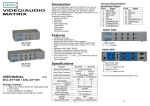
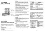
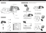
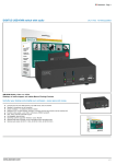
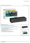
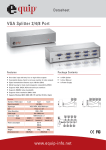
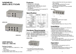
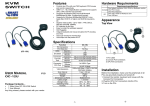
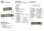
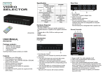
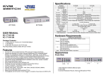
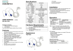
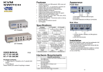
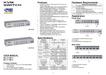
VIDEO SELECTOR (VRM-714E) Features Resolution up to 1920x1440. Pixel frequency up to 250MHz. Supports the DDC1, DDC2, DDC2B, DDC2B+, DDC2AB. (For video out port 1) Hot pluggable. Auto skip over the powered off and suspended PC, and the unplugged VGA cable. (VRM-712E, ej lagervara) Connector (VRM-718E, ej lagervara) e-mail: [email protected] tel: 08-52 400 700 fax: 08-520 18121 CPU HD-15 Female Monitor HD-15 Female On Line LEDs Selected Select Switch VGA Resolution Power Adapter (Min.) Housing Weight Dimensions (LxWxH) mm VRM-712E VRM-714E VRM-718E 2 4 8 1 1 1 2 2 2 4 8 4 8 4 8 1920x1440 250MHz DC 9V 300mA Metal 400 g 420 g 680 g 128x75x45 200x75x42 Hardware Requirements Monitor (Projector) PC Cable Requirement specifications One highest resolution VGA, SVGA, Multisync, PLASMA monitor or projector. One VGA, SVGA or Multisync card. Standard cable. FRONT VIEW 1. Power Supply Plug the DC9V 300mA power adapter. 2. Video Connector Plug the monitor cable. 3. CPU Port Connectors Plug the extension cables from VGA port of PCs. Installation Before the installation, making sure the selector and monitor (projector) are turning off. 1. Making sure all equipments are turned off. 2. Plug the monitor cable into the Video Connector. 3. Plug the extension cables from VGA port of PCs into the CPU Port Connectors. 4. Plug the power adapter into the wall socket. 5. Connect the power adapter with the video selector. 6. All red LEDs will flash, otherwise, go back to check the step 4 and 5. 7. Turn on the PCs and monitor. 8. The LEDs green lights turn on while the PCs have well been connected and maintaining the activation. Operation Package Contents 1 Smart View VRM-712E or VRM-714E or VRM-718E Video Selector 1 user manual 1 power adapter DC 9V 300mA Any thing missed, please contact with your vendor. Rear View Specification Function (VRM-714E, art.nr. 25-0060) All the red LEDs flash while the power adapter is well connected. Green LEDs light up while the PC has well connected and starting operation. Red LEDs light up while the PC has successfully been selected. 1. Port Selection Switches (Manual type) Press the switch to access the chose PC. 2. Port LEDs -1- 1. Port selection Press the button of “port selection switch” for accessing the wanted PC. The selected corresponding port will light on for the red LEDs which indicating the port is actived. -2-