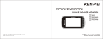
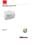
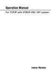
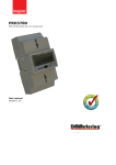
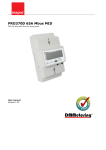
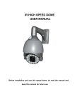
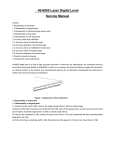
1
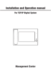
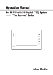
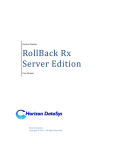
Installation and Operation manual
For TCP/IP Digital(300) System
For Indoor Monitor
Remark
Please follow the user manual for correct installation and testing, if
there is any doubt please call our tech-supporting and customer
center.
Our company applies ourselves to reformation and innovation of
our products. No extra informing for any change. The illustration
shown here only used for reference, if there is any difference
please take the actual product as standard product.
CATALOG
Product Features
Technology Parameters
Picture
Home Page
Operation
4
1. Home security
4
2. Intercom
9
3. Message
13
4. System setting
14
5. Screen saver
19
6. Touchscreen Calibnation
19
System Configuration
20
Connection Diagram
21
Installation instruction
24
Failure Diagnosis
25
Notes
25
Product Feature
1. Touch screen.
2. Friendly interface, easy use.
3. Intercom with Outdoor panel, flat panel and Management Center.
4. Support 8 alarm stations (Smoke, Gas, PIR, Door Sensor.etc)
5. Monitor Max. 8pcs IP cameras (ONVIF protocol).
6. Audio intercom between each indoor monitor.
7. Image records from outdoor panel.
8. Message receiving from management center, Max. 64pcs.
9. Easy installation, use international standard RJ 45.
10. Use TCP/IP protocol base on LAN network, no distance and apartment
quantity limitation.
11. Easy maintenance, software upgrade with SD card.
12. Support standard SIP protocol (optional).
Technology Parameter
Voltage: DC 12V
Operating temperature: 0℃~+50℃
Rated power: 4W
Standby power consumption: 2.5W
Talking mode: bi-directional communication
Talking time: 2 minutes
Broadband upward capacity: 768K
Storage condition: 0℃~+60℃
-1-
Picture
Model: I2
1
2
3
4
5
6
7
8
1
Handsfree
5
Power indicator
2
Monitoring
6
Message indicator
3
Unlocking
7
Alarm setting indicator
4
Calling Management center
8
Alarm indicator
-2-
Home Page
The main interface is the entrance of indoor monitor operation.
Main menu: Home security, Intercom, Message and System Setting.
Status bar illustration:
Message: click to read the message.
Mute mode: click to set ON or OFF mute mode
Alarm status: you’ll hear “di-di” tone when setting up, to indicate your
alarm sensors will operate after 100 seconds.
Network mark: connect with network properly or not.
-3-
Operation
1. Home Security
Each indoor monitor can be connected with maximum 8 alarm zones
(whether you system can support sub indoor monitor or not, check the system
provider, kindly note the sub indoor monitor is not allowed to connect with alarm
zones ). Click
icon on the main interface, the system will enter the following
interface:
1. 1 Alarm ON/OFF
There are three security alarm modes for option: Outside, At home & Sleep.
1.1.1 To alarm
Click “Outside”, “At home” or “Sleep” icon to activate the alarm sensors, the
icon
on the main interface will light up with a “di-di” tone lasting for about 100
seconds. After 100 seconds, the security alarm will operate and the icon
always light up.
-4-
will
1.1.2 Stop Alarm
During the alarm delay time, Click
icon , the system will sound a tone,
then the alarm is stopped.
1.1.3 Alarm OFF
If the system is on “Alarm ON” mode and need to cancel the alarm, now
you must input the user password with 4 digits (the default password is 1234).
-5-
1.2 Zone setting
Click
icon, then enter the user password with 4 digits (the default
password is 1234), then enter the following interface:
Remark: If the system is on “Alarm ON” mode, zone setting cannot be
operated.
1.2.1 Alarm Type
Click Type setting box, it will popup a dialog box as the following . Three
alarm type for your optional : Normal, Emergency & 24 Hour.
The 24H and Emergency alarm are always active.
-6-
1.2.2 Delay Time
Click Delay setting box, it will popup a dialog box as the following
interface, there are several different delay time you can set with followings: 0s,
5s, 10s, 15s, 20s, 25s, 40s and 60s. For example, you select the delay time:
5S. Once the alarm sensor is triggered, 5 seconds later, the indoor monitor will
sound sirens.
Remark: when alarm type is set as Emergency or 24 Hour, the delay time
can only be set as 0s.
1.2.3 Sensor Type
Click Sensor type setting box, it will popup a dialog box as the following
types: Smoke, Gas, PIR, Door, Window, Panic, Flood, Pull Cord and Bed Mat.
-7-
When alarm sensor is triggered, the indoor monitor will make a loud alarm
sound, the system will enter into the following interface, and send alarm
message to management center (if your system installed management center):
You can see the No. and sensor type in red color showed at the top pf
interface. For example: "1:Smoke" to indicate that Zone 1, Smoke sensor is
triggered.
To stop the alarm sound, input the password (the default password is
1234).
1.3 Scene setting
Click “Scene setting” icon, then enter the user password with 4 digits (the
default password is 1234) to enter the following interface:
-8-
Click the input box to choose the scene mode and alarm stations as your
need. Once you choose it, it will show a
icon.
Remark: If the system is on “Alarm ON” mode, scene setting cannot be
operated.
1.4 IP Camera
Click
icon, the system will enter into the following interface (For the
setting of IP Camera, please refer to Installation& Settings Instruction):
Click
or
to select the monitor area, then click
IP Camera. If want to cancel monitor, click
button.
2. Intercom
Click
icon, the system will enter into the following interface:
-9-
to monitor
2.1 Calling other indoor monitors
Click
icon in the intercom, the system will enter the following interface:
Input 4 digits of Building No. +2 digits of Door No. + 4 digits of Room
No., then press
icon to call the resident. For example, if input Building
0001, Door 01, Room 0001, you can input “1” + “Building” + 1+ “Door” +1,
the system will add zero automatically. If input wrong, click
to delete. If
the Building No. and Door No. is consistent, you can also input Room No.
directly.
2.2 Calling your sub indoor monitors
If it connects with sub indoor monitor, click
device to make internal intercom.
-10-
to select the corresponding
2.3 Answer the call
When someone calls in, the system will enter into the following interface:
Click “Answer” to star intercom; click “Hang up” to stop the call; If no one
answers the call, and the calling time exceeds 25s, the system will snap the
visitor’s image automatically. During the communication, click “Snapshot” icon,
the system will snap the visitor’s image, one image one time. The max. quantity
of image store is 64 pcs. Cilck “Unlock” to unlock the door.
2.4 Calling the management center
Click
icon , it will enter the following interface:
The system can connect max. 5 pcs management center. Click
icon
to call the management center, when center 1 is busy, it will call the next
management center from 2~5.
-11-
2.5 Monitor
Click
icon to enter following interface. Press
icon, you’ll see the
video from the outdoor station.
To monitor other door stations( if they installed in the same system), by
clicking the
or
icon on the following interface, you can choose to monitor
the outdoor station from unit 1 to unit 10, and secondary door station: sub1 &
sub 2, click
Click
icon to start monitoring. Click
icon to cancel monitoring.
icon to unlock the door.
2.6 Records
To check the call records, click
icon on the intercom interface, it will
show you the followings:
is refer to outgoing call;
is refer to received calls;
calls.
-12-
is refer to missed
: page up;
: page down. Click
icon to delete, click
icon to
call back. The max. quantity of records is 20 pcs.
Icon
indicates the calling was from the outdoor station with snapshot
image, click to see the image.
Click
icon, the system will enter into the following interface:
Click
button, the system will play the snapshotted pictures
automatically; Click
button to stop playing pictures; Click
button to go
back to previous menu.
3. Message
Note: only install the management software on PC which usually locate at
guard center, the indoor monitor can receive the message sent by PC.
Click
icon in the main interface, the system will enter the following interface:
1
2012-08-12 10:59
2
2012-08-12 11:00
3
2012-08-11 10:00
4
2012-08-10 12:00
-13-
is refer to the unread message. When there are some unread
messages, the icon
in the interface will light up, and when enter the
message interface, the icon will light off.
Click
icon to page up.Click
icon to page down. Click
icon to
delete the record.
4. System settings
Click
icon on the main interface, it will show you the followings:
4.1 Adjust
Click
icon on the main interface, it will show you the followings:
Click the sliding button left or right to adjust the brightness or contrast.
-14-
4.2 Date & Time
Click
icon to enter the following interface, then you can set the time.
Remark: When the power recovers after outage, the date and time will be
returned to factory default mode, you must set it again. If the indoor monitor
connects with management software or Internet, the date and time will be
synchronized automatically.
4.3 Sound
Click
icon to enter the following interface:
You can set System, In-call volume, Ring tone and Key tone.
-15-
4.4 Version
Click
icon to enter the following interface. You can read the version
information in the following interface.
4.5 LAN
Warning: end users are not allowed to set this menu.
Click
icon, input the system password with 6 digits, then the system
will enter into the following interface (For the setting of LAN, please refer to
Installation &Settings Instruction ):
-16-
4.6 Room No.
Warning: end users are not allowed to set this menu.
Click
icon, then input the system password with 6 digits to enter the
following interface (For the setting of Room No., please refer to Installation
4.7 User PSW
Click
icon to enter the following interface, you can set the new user
password with 4 digits (the default password is 1234).
-17-
4.8 Language
Click
icon to enter the following interface:
Select the language you want, then click “Confirm”, the system will restart
within 1 minute, and it will change into the language you selected.
4.9 Upgrade
Warning: end users are not allowed to set this menu.
Click
icon, then input the system password with 6 digits to enter the
following interface (For the setting of Upgrade, please refer to Installation&
Settings Instruction ):
-18-
4.10 System password
Click
icon to enter the following interface, you can set the new system
password with 6 digits (please refer to Installation& Settings Instruction ).:
5.Screensaver
If it is on stand-by mode for 2 minutes, the system will switch into
screensaver mode. If there is no image in SD card, the screensaver will display
as the clock; if there are some images in SD card, the screensaver will display
as images which are stored in SD card, the screensaver time is only 10
minutes.
6.Touchscreen Calibnation
When you touch the screen and find the icons cannot react normally,
please make the screen calibnation by yourself. Slowly sliding along horizontal
or vertical on the LCD, or press “Unlock” button for 5 seconds, the system will
enter into the following interface. Click the center of cross intersection from 1 to
5 in turn. After adjustment, the system will be exited automatically.
int
1
2
5
3
4
-19-
System Configuration
System Configuration
Next network switch
Alarm
(optional)
Siren
(optional)
Network
switch
Indoor monitor
2F
Adapter
Indoor monitor
Adapter
Network
switch
Adapter
1F
Adapter
Main Indoor monitor
Indoor monitor
Guard center
or
2
3
*
4
5
6
0
7
8
9
#
1
CAR
Outdoor Panel
D
PC
RVV3x0.75
RVV2x0.75
Lock
Sub Indoor monitor
UPS-DP/P
Remark: 4pcs indoor monitors can use 1pc adapter, or each indoor monitor can
use 1pc separately.
-20-
Connection Diagram
Indoor monitor
V+
Siren
NC1
V1+ GND
NC2
To network switch
CAT 5e
NC3
NC4
NC5
NC6
NC7
NC8
DC12V
Electric current
GND
No use
-21-
1.The alarm sensor is normally-open:
Sensor
传感器
Sensor
传感器
Resistor 2.2K
Resistor 2.2K
Sensor
传感器
Resistor 2.2K
Sensor
传感器
Resistor 2.2K
Sensor
传感器
Sensor
传感器
Sensor
传感器
Sensor
传感器
-22-
Resistor 2.2K
Resistor 2.2K
Resistor 2.2K
Resistor 2.2K
2.The alarm sensor is normally-close:
Sensor
Resistor 2.2K
Sensor
Resistor 2.2K
Sensor
Resistor 2.2K
Sensor
Resistor 2.2K
Sensor
传感器
Resistor 2.2K
Sensor
Resistor 2.2K
Sensor
Resistor 2.2K
Sensor
Resistor 2.2K
-23-
Installation Instruction
86 box,embeded
inside the wall
Back
hanger
-24-
Fix 86 box, 2pcs
screws.
Failure Diagnosis
Defec.
Judgement
Operation
Unable to start
the product
If connect the power adaptor?
To connect the power adapter.
Speaking state
no voice
If the volume is adjusted to be
the least?
To adjust the volume to be
suitable.
The image is
flashing or
noise
If the indoor monitor device is
Keep the device off these
close to TV set, fluroscent lamps, things which has electronical
mobile phone, which has
and magnetic wave.
electronical and magnetic wave?
Notes
Notes
Maintenance of devices
1. Keep the clearance of the surface and use soft dry cloth to clean the dust of the
product.
2. Please turn off the power of indoor unit when clean the indoor device.
3. If there is hard dirty which cannot be cleaned with dry cloth, please use the soft towel
dipped in the neutral diluted detergent to clean the machine and then clear it with dry
cloth.
4. Do not use benzene, thinner or organic solvents such as gasoline to clean, these
solvents may cause damage to the machine casing or the surface of machine and
change colors.
Matters need to be noticed
1. Read the instructions in this handbook carefully. Be sure to keep it for future reference.
2. Be sure to use only the supplied AC adapter and that your power source matches the
rating listed for it. If you are not sure, check with your dealer or with your local power
company.
3. Avoid strong hits or shocks. Do not use the AC adapter if it is has received any hard
knocks or looks damaged in any way; immediately contact an authorised service center.
4. The product should be placed where is stable, windy, air-dry, non-sunshine, non strong
magnetic and non dusty.
5. Don’t clean the surface with chemicals but with soft and clean dry cloth.
6. Don’t press several buttons at the same time.
7. The outdoor and indoor unit must be matched with appointed specified models and
cannot match with others that are not our products.
8. Don’t disassemble the machine without authorization, if the need for fault repair, please
contact the distributors or the company’s tech-supporting department.
-25-