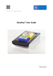
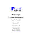
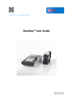
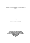
1
GRAPHIC DISPLAY VERSION 3.1 a.k.a. GDISP31 A Comprehensive Functional Specification of an intelligent controller for a Hyundai HG25504NG-01 256x128 LCD Graphics Display Module Duane Becker September 27, 2005 Table Of Contents DESCRIPTION ...........................................................................................................................................................................3 EMBEDDED FEATURES ..............................................................................................................................................................3 HARDWARE INTERFACE DESCRIPTION .......................................................................................................................................3 Hardware Pinout.................................................................................................................................................................4 Timing Diagram of a Typical Byte Transfer ........................................................................................................................4 Interface Timings ................................................................................................................................................................5 Electrical Specifications......................................................................................................................................................5 MEMORY MAP OF THE HYUNDAI DISPLAY CARD.......................................................................................................................5 COMMAND SUMMARY ..............................................................................................................................................................8 COMMAND DESCRIPTIONS ........................................................................................................................................................9 Z - Mode Selection ..............................................................................................................................................................9 D - Display Selection ........................................................................................................................................................10 E - Edit Pages Selection....................................................................................................................................................11 S - Switch The Active Pages ..............................................................................................................................................11 C - Clear and Home The Text Page...................................................................................................................................12 W - Wipe Clean The Graphics Page ..................................................................................................................................12 L - Line .............................................................................................................................................................................12 F - Fat Line.......................................................................................................................................................................14 N - Dashed Line ................................................................................................................................................................14 U - Unbroken Chain Of Lines............................................................................................................................................15 P - Position Text Pointer ...................................................................................................................................................16 T - Text .............................................................................................................................................................................16 B - Box..............................................................................................................................................................................18 I - Initialize .......................................................................................................................................................................19 H - Home ..........................................................................................................................................................................20 O - SetDot .........................................................................................................................................................................20 A - Alarm ..........................................................................................................................................................................20 K - Kursor.........................................................................................................................................................................21 R - Restore The Kursor Area .............................................................................................................................................21 G - Graphics Symbol Instantiate........................................................................................................................................22 Q - Double-Size Symbol Instantiate ...................................................................................................................................24 M - Make Graphics Symbol ...............................................................................................................................................25 Y - Yank Graphics Into A User Symbol ..............................................................................................................................26 X - XOR Symbols...............................................................................................................................................................27 z - Graphic Virtual Text Characters Block Size Command.................................................................................................27 t - Graphic Virtual Text Characters String Plotting ...........................................................................................................29 p - Graphic Virtual Text Characters Cursor Position ........................................................................................................29 V - Video Block Transfer ...................................................................................................................................................30 e - Ellipse..........................................................................................................................................................................33 COMMAND SUMMARY CARD ...................................................................................................................................................34 GRAPHICS SYMBOL SET FOR GDISP3 CONTROL CARD ............................................................................................................35 GRAPHICS SYMBOL LISTING ...................................................................................................................................................36 CONTROLLER CARD COMPONENT LAYOUT ..............................................................................................................................39 GDISP3 SCHEMATIC ..............................................................................................................................................................39 VOLTAGE INVERTER COMPONENT LAYOUT .............................................................................................................................40 VOLTAGE INVERTER SCHEMATIC ............................................................................................................................................40 2 Description This manual describes the functional operation of the GDISP3 front end control card for a Hyundai HG25504NG-01 display panel (available from AllElectronics). The front end card and firmware of the control card simplifies the interface and use of the display panel. The panel natively accepts byte reads, byte writes, and configuration commands, but supports no high-level commands. This front-end card handles all the work needed to configure and control the panel and provide high-level drawing and text tools to speed development of a project. A parallel interface port with -STROBE, -ACK, and +BUSY signals allows the card to be controlled with a printer port or any parallel interface. The display module itself is black dots on white background, and requires about -15 Volts on its LCD backplane voltage pin. The response time of the display is pretty slow, about 200 milliseconds to any change, so rapidly changing display data will not show up well. This implies that dynamically moving cursors might be difficult to track. You can use the user-symbols to implement a cursor trail if desired. Embedded Features ⇒ ⇒ ⇒ ⇒ ⇒ ⇒ ⇒ ⇒ ⇒ ⇒ ⇒ ⇒ ⇒ ⇒ ⇒ 256 dots wide, 128 dots tall Contrast Control Single 5-Volt operation Standard Parallel Port Interface Two operational modes: 2 text pages + 1 graphics page (2T+G), or 2 graphics pages (2G) Can select which text page or graphic page is displayed Can enable or disable text and graphics display independently Independent control of which pages are selected for editing Many built in text, copy, and drawing tools Built in bitmap transfer command Sixteen user-definable graphic symbols, 240 predefined graphic symbols 5×5 pixel, fast, sprite based graphic cursor Built in audible alarm (1/4 second beep duration) GDISP3.EXE allows testing the smart controller’s functions from a PC. CONVBMP.EXE allows converting a black and white bitmap to a video transfer command data sequence. Hardware Interface Description The parallel-port connection to the controller has eight data lines, a -STROBE line, +BUSY line, and a -ACK (acknowledge) line. The data lines are unidirectional and send data to the display. When pulsed low, the -STROBE line commands the display interface that new data is available on the data lines. The -ACK line drops and the +BUSY line rises as soon as a low to high transition on -STROBE occurs. When the control card has read the bus data, it resets the -ACK line to a high, indicating to the host that the data has been accepted and the data lines may be released. The +BUSY line indicates to the host that the controller is busy processing the last command or data byte. The host must first ensure that the +BUSY line is low before strobing the next command or data byte transmission. The +BUSY line 3 stays at a high level until the data byte or command is completely processed. Hardware Pinout Interface Pin Number of J1 1 2 3 4 5 6 7 8 9 10 11 12 13 Pin Name +5 Volt Power Supply +BUSY -ACK -STROBE Data Bit 0 Data Bit 1 Data Bit 2 Data Bit 3 Data Bit 4 Data Bit 5 Data Bit 6 Data Bit 7 Ground Pin Type Power Output Output Input Input Input Input Input Input Input Input Input Power Return Timing Diagram of a Typical Byte Transfer 4 Interface Timings Parameter Minimum Maximum tSUP 0 --tS 30 --tACK 1.5 3.0 tHOLD tBUSY 0 --- --0.8 Units Description ns Data setup before rising edge of -STROBE ns -Strobe width Time for controller to acknowledge a µs strobe ns Data hold after -ACK rising s Time to execute command (command dependent) The normal process of sending a byte of data is: 1) 2) 3) 4) 5) 6) Ensure that the +BUSY line is at a low state (not Busy) Apply a data byte to bus Drop the -STROBE line Raise the -STROBE line Wait until the -ACK line has returned to a high state. Tristate the data bus (optional) The usual time that you have to wait for the -ACK line to return high after issuing a -STROBE rising edge is two microseconds. You may also use just the +BUSY line as a command and data throttling signal without using the -ACK line. That process is presented here: 1) 2) 3) 4) 5) Ensure that the +BUSY line is low (not busy) Apply the data byte to bus Drop then raise the -STROBE line Wait at least three microseconds for the control card to grab the data Tristate the data bus (optional) The standard PC printer port supports the +BUSY/-ACK protocol and the +BUSY only protocol. Electrical Specifications Parameter VCC ICC VIH VIL FALARM tEDGE Note 1: silent, Note 2: typical Minimum 4.75 70 2.6 -0.2 0 Maximum 5.25 85 VCC+0.3 0.8 2.3 1 Units Volts milliAmps Volts Volts KHz µs Description Power supply voltage Power supply current (See Note 1) Input high level Input low level Alarm tone frequency (See Note 2) Signal rise and fall times When the alarm is sounding, the maximum specification applies. When the alarm is the minimum specification applies. There is no minimum or maximum for alarm frequency. The value indicated is the value. Memory Map Of The Hyundai Display Card The display module has 8192 (8K) bytes of memory on-board. The smart controller card allocates this memory in two ways, depending on the operational mode that is selected. This diagram describes how the 8K of memory on the display module is allocated by the GDISP3 control card's 5 firmware. Normally, the user does not need to know about the internal memory allocation of the display, since the control card provides the high-level command interface to the user. Addresses (Hexadecimal) 0000 .... 01FF 0200 .... 03FF 0400 .... 0FFF 1000 .... Mode 0 (2T+G) Mode 1 (2G) Text 0 Text 1 Graphics 1 CGRAM (not used) Graphics 0 Graphics 0 1FFF You may use the Mode command to select Mode 0 or Mode 1, and the Display and Edit commands to set other parameters allowing you to edit and display different pages. Mode 0 supports two text pages, and one graphics page. Mode 1 supports two graphics pages and no text page. You can, however, instantiate symbols and text onto a graphics screen. The Graphics 0 page is available in both modes. The smart card handles all the byte and bit addressing based upon simple screen position parameters in the commands. Each of the two paired pages in each mode can be edited or displayed independently. That is, you can edit one while the display shows the other, or you can edit the one you're actually looking at. You can even edit a page and display neither page. For example, in mode 0, you have graphics page 0, and text pages 0 and 1. Graphics page 0, the only graphics page in mode 0, is always available for editing, but may be selectively displayed or hidden. The two text pages are independently edit-selectable and displayable. You may select either or neither text page to display. and you may select which text page is active for editing (whether displayed or not). The text pages are 32-characters across and 16-characters tall. Each character sits inside an 8×8 pixel box. The graphics pages are 256-pixels wide by 128-pixels tall. The text characters are logically ORed with the graphics drawings so that graphics shows through the whitespaces of the text characters. Erasing text characters does not alter the graphics data since they held in separate areas of the display memory. In mode 0, you are limited to editing only graphics page 0, but may enable or disable its display. You have free selection about which text page to 6 edit, and which text page (or neither) to display. This allows you to formulate a new text page while displaying the other, if you so desire. In mode 1, you have two independent graphic windows, and full control of which (or neither) is displayed, and which one is selected for editing. This independent control allows you to compose a new graphic screen while the other one is being displayed, if so desired. 7 Command Summary In this document, “page” refers to the text or graphics page of data. This is not necessarily the same page that is being displayed since you can edit a graphic or text page of data that may or may not be currently displayed. This allows building new pages of data while the old page is still being displayed, which can be used to provide snap updates to the display while hiding the display building process. Command Character Z D E S C W L F N U P T B I H O A K R G Q M Y X z t p V e Command Description Mode Selection (to select 2T+G or 2G operating modes) Display selection (which pages are displayed) Edit selection (which graphic and text pages are editable) Switch the pages being displayed and those being edited Clear the text page selected for edit and home the character pointer Wipe clean the graphics page selected for editing Draw a line from one coordinate to another Draw a Fat line from one coordinate to another Draw a dashed line with adjustable dash lengths Unbroken chain of lines on screen Position the text pointer to a row and column Send text characters to the text page selected for editing Draw an opposite-corner specified rectangular box with various attributes Initialize the entire display to reset conditions Send the text pointer to the home position (upper left) Dot command sets or clears any specified dot Alarm sounds for 1/4 second Place a graphics cursor on the currently edit-selected graphics page while saving the graphics dots for later restore Restore the graphics cursor pixels turned on by the Kursor command Graphic symbol instantiating to the graphics page Double-sized symbol instantiation to the graphics page Make symbol - allows defining your own graphic symbol Yank graphic symbol allows yanking an 8x8 symbol off graphics screen to a user symbol XOR two symbols together into a user symbol set the horizontal and vertical graphic text spacing Plot text and symbol strings to the graphics layer Position the virtual graphic text pointer to a row and column Video block transfer Ellipse command Note: The following letters are not used by the controller for commands: J, abcd fghijklmnopqrstuvwxyz 8 Command Descriptions Some of the controller commands are single ASCII characters and some include additional data bytes that supply values and data needed by the command. Each space-separated element in the command format represents one byte, either an ASCII character or an 8-bit byte. The times for execution are based on using a 24 MHz crystal for the processor and include the time spent sending the commands to the controller over the parallel bus. Z - Mode Selection Command Format: Z mode There are two modes of operation. The command is first activated by sending the ASCII character “Z” (5Ah). Then send either a zero byte (00h) for mode 0 or any nonzero byte for mode 1. Mode 0 supports two selectable text screens (T0 and T1) and one graphics screen (G0). The selected text screen is transparently ORed with the graphics screen dots on the display, but are in physically separate portions of memory. In mode 0, you can independently select which of the two text screens to edit, and which of the two text screens to display. The graphics screen (G0) is automatically selected for editing and display. You may turn the selected text screen and/or the graphics 0 screen on or off at will, independently of each other. Mode 0 is useful if you don’t change graphics screens too much, and need to independently incorporate text into the display without having to redraw the graphics screen. Mode 1 supports two graphics screens (G0 and G1) and no text screens. You may select which graphics screen is displayed (or none of them), and you may select which graphics screen is selected for editing. You may edit either the displayed or the nondisplayed screen. Mode 1 is useful if you are frequently redrawing the graphics data, and want to be able to draw the new screens while hidden, and present the finished screen to the user only when its composition is complete, thus eliminating the on-screen drawing distraction. When you select mode 0, the following things occur: 1. Both text screen layers are cleared to all spaces 2. Text page 0 is selected for editing and for display, and the text screen is turned on for display (although it is set to all blank spaces). 3. The text pointer is reset to row 0 and column 0 (upper right). 4. Graphics page 0 is selected for editing and display, and is enabled for display, but it is not cleared. When you select mode 1, the following things occur: 1. The text 2. Graphics 3. Graphics display, screens are disabled page 1 is cleared to all whitespace. page 0 is selected for editing and display, and is enabled for but is not cleared. The Z mode selection command executes in 56 milliseconds. 9 D - Display Selection Command Format: D n This command allows selection of which graphics page and which text page is selected for LCD screen display, and whether the selected graphics and/or text pages are displayed. Either, both, or none of the selected pages may be displayed. The first byte is the ASCII character capital “D” (decimal value 68, hex value 44h). The second byte selects the pages and their on/off status. The display selection parameter byte (n) is composed of four bit-fields: 7 0 6 0 5 0 4 0 3 Graphics Turned On 2 Graphics Page Selector 1 Text Turned On 0 Text Page Selector Graphics Turned On - when 1, the graphics page selected by bit 2 is shown on the display. When 0, the graphics page display is turned off Graphics Page Selector - This selects which graphics page (0 or 1) is allowed to be displayed. Text Turned On - when 1, the text page selected by bit 0 is shown on the display. Text Page Selector - This selects which text page (0 or 1) is allowed to be displayed. Note that in mode 1 (2G), the text control fields are ignored since there is no text window. In mode 0 (2T+G), the Graphics Page Selector bit is ignored and is forced to 0 since there is only graphics page 0 in mode 0. Examples: Command "D" 00001010b "D" 00001110b "D" 00001011b "D" 00000101b "D" 00001111b "D" 00001100b "D" 00001000b Mode 0 (2T+G) Behavior Display graphics page 0 and text page 0 Display graphics page 0 and text page 0 (the second “1” is ignored in mode 0 Display graphics page 0 and text page 1 Displays neither graphics nor text pages Display text page 1 and graphics page 0 (no graphics page 1 in mode 0) Displays graphics page 0 (mode 0 only has one graphics page) Display just graphics page 0 Mode 1 (2G) Behavior Display graphics page 0 Display graphics page 1 (there are no text pages in mode 1) Display graphics page 0 (there are no text pages in mode 1) Displays neither graphics page Display graphics page 1 (no text pages in mode 1) Display graphics page 1 Display just graphics page 0 You can use this command to FLASH the display, graphics and/or text, on and off by first displaying the data, then turning the displayed page off, then repeating at your own desired rate. The display select command executes in 275 microseconds. 10 E - Edit Pages Selection Command Format: E n This command allows you to select which graphics page and which text page are allowed to be edited. This is a two byte command. The first byte is the ASCII character "E". The second byte selects which pages are editable: 7 0 6 0 5 0 4 0 3 0 2 0 1 Graphics Edit Selector 0 Text Edit Selector A “0” in a selector bit directs editing into page 0 of the graphic or text page. A “1” in a selector bit directs editing into page 1 of the graphic or text page. Editing consists of any operation that changes the page composition (like adding characters, clearing, inverting, etc.). Examples: "E" "E" "E" "E" Command 00000000b 00000001b 00000010b 00000011b Enable Enable Enable Enable edit edit edit edit Command Description of graphics page 0 and of graphics page 0 and of graphics page 1 and of graphics page 1 and text text text text page page page page 0 1 0 1 When an edit selection is made that is not supported by a particular mode, (such as selecting a text page to edit when in graphics only mode), the selection bit is ignored. The Edit select command executes in 100 microseconds. S - Switch The Active Pages Command Format: S This command simplifies the editing and display control of two screens of data. If you are dynamically changing the screen, you can display one set of pages, while you edit the other set of pages. When you are done creating the second set of pages, you can SWITCH, and the selected pages for display will be flipped and the selected pages for editing will also be flipped. This is the easiest way to swap between creating and displaying two pages, and allows display of a stable picture while you edit and create a second picture. Of course, you can edit and display the same pages if you desire to watch the creation of the data dynamically. This command takes no arguments. Just send the character "S" (capital S in ASCII). In mode 0 (2T+G), the switch command only toggles which text screen is displayed and edited. In mode 1 (2G), the switch command only toggles which graphics screen is displayed and which one is selected for editing. NOTE: Switching from one text page to the other does not alter the character pointer (row and column) for next text. You may desire to use one of the cursor altering commands to reset the text pointer before sending characters to the switched into text page. The “H” home, “P” position, and “C” clear text commands all are likely candidates. 11 Example 1 (commands are in sequence): "Z" 00000000b "E" 00000001b Select mode 0 (display and edit G0 and T0) edit G0 and T1 ... text and drawing commands go into pages G0 and T1 while G0 and T0 are being displayed ... "S" Switch so that page T1 is displayed and T0 is selected for editing. Example 2: "Z" 00000001b "E" 00000010b Select mode 1 (display and edit G0) Edit G1 ... graphic drawing commands go into page G1 while G0 is being displayed... "S" Switch so that page G1 is displayed and G0 is selected for editing. The switch command executes in 172 microseconds. C - Clear and Home The Text Page Command Format: C Send the single byte command ASCII "C" (capital C), and the text page currently selected for editing (not necessarily the displayed one) is cleared to all spaces. This command also resets the text row and column pointers to 0,0 (the top row, leftmost column). If the edit selected text page is ALSO selected for display, you will see the clear take place immediately. You may clear the NON displayed text page if it's set up for editing. The clear text command executes in 8.1 milliseconds. W - Wipe Clean The Graphics Page Command Format: W Send the single byte command ASCII "W" (capital W), and the graphics page currently selected for editing (not necessarily the displayed one) is cleared to whitespace. This command does not clear out any actively stored "K" cursor saved command. The non-edit-selected graphics page is not cleared. If the currently selected-for-edit graphics page is also selected to be displayed, you will see the screen wipe take place immediately. You may clear the non-displayed graphics page if it's set up for editing. This does not clear any text placed using the "T" text command. Since mode 0 has only one graphics page, the WIPE command will always target graphics page 0 in mode 0. The wipe command executes in 54 milliseconds. L - Line Command Format: L x1 y1 x2 y2 12 This draws a single-pixel wide line from the first X,Y coordinate pair to the second X,Y coordinate pair. The LCD is 256-pixels wide and 128-pixels tall. The range of values allowed for Y are from 0 to 127 inclusive. You should not send a Y value outside of this range for any graphics command using dot coordinates. Since the graphic area is 256-pixels wide, and one byte exactly covers the range of 0 to 255, the value of the X parameters can be any byte value. To draw a standard thin line in your currently edit selected page, send the character "L" (capital L), then the two bytes representing the X,Y location of one end, and two more bytes representing the other X,Y endpoint. The screen coordinate system is set up to be mathematically correct where the lower left dot is located at X=0,Y=0 and the upper right dot is located at X=255,Y=127. No error checking is performed. If you specify a Y value larger than 127, other portions of the display memory might be affected. Both endpoints should be in the graphics page field. For example: "L" 00010100b 00001011b 11111010b 01101111b 14h 0Bh FAh 6Fh 20 dec 11 dec 250 dec 111 dec That 5 byte command will draw a line from 20,11 to 250,111 . To estimate a line draw time, use the benchmark of 157 microseconds for each dot in the long dimension. Thus the line 0,0 to 255,127 takes 256 dots x 157 microseconds = 40.3 milliseconds to complete. Graphic Dots Page Layout 13 F - Fat Line Command Format: F x1 y1 x2 y2 This performs the same basic function as the “L” line command, except that the line drawn is 3 pixels fat and the drawing time is almost three times as long as the single line. No error checking is performed on the Y endpoints. You should not send a Y value greater than 127. The graphics screen is 256 dots wide in the X dimension, so any value is permitted for X. The Y axis is limited to coordinate values from 0 to 127. Essentially, this command draws three lines side by side, offset in the Y axis if the major length is along X, and offset in the X axis if the major length is along Y. If any of the outer lines has dots that fall off the screen, those dots will not be drawn. If you draw a fat line along an edge of the screen, it will only be two dots wide since the outermost line is offscreen and is not drawn. Since this routine draws lots more dots, it takes longer to draw a fat line, so use fat lines judiciously. For example, the command “F” 0 0 172 100 results in the line shown here: This command executes in 109 milliseconds for a 256-dot long line or about 426 microseconds per dot for the longest axis length. N - Dashed Line Command Format: N dashlong x1 y1 x2 y2 This performs the same basic function as the “L” line command, except that the line is drawn in dashes and is drawn faster than a regular line since only half as many dots are turned on. The portion of the line that is not drawn (between the dashes) is not cleared off the graphic space. In other words, the line gaps are drawn transparently, so other data can show through. The value 'dashlong' represents how many dots are used for dashes and non-dashes and is valid from 1 to 15. In the following situations, a simple solid line is drawn instead of a dashed line: a) If the b) If the long. c) If the of the value 'dashlong' = 0 or 'dashlong' > 15 longest dimension (x or y) of the line is less than three dots longest dimension of the line is less than or equal to the length dash specified. 14 No error checking is performed on the Y endpoints and they should be from 0 to 127. Since the panel is 256 dots wide, any byte value is allowed for the X coordinates. The dashes are adjusted in length for diagonal lines so that the dash length is kept approximately the same regardless of the angle of the line. A dashed line always has a full dash at the starting end (x1,y1), and a partial dash or a single dot at the trailing end (x2,y2). For example: “N" 5 10 20 200 120 will draw a dashed line from 10,20 to 200,120 using dashes that are 5 dots long, and looks like this: This command executes in 26 milliseconds for a line of length 256 dots in the long axis. U - Unbroken Chain Of Lines Command Format: U x1 y1 x2 y2 x3 y3 ... xn yninvalid This command draws a chain of line segments, each successive point joined to the previous segment. Send the "U" character to start the chain, then send the first x,y pair. Each successive x,y pair sent thereafter draws that next line segment, and prepares for the next in the chain. To end the command, send an X,Y pair with an invalid Y value (Y>127). The command “U” 10 (X1 10 Y1 200 X2 100 Y2 50 X3 43 Y3 255 X4 20 Y4 0 128 Xn Yinv) draws this: 15 This command draws the lines at the same rate as normal lines, namely about 157 microseconds per dot of the longest dimension. P - Position Text Pointer Command Format: P row col This command positions the text address pointer to row (0 to 15) and column (0 to 31) so the next text command will place text characters at that location on the text page selected for editing. The rows range from 0 at the top to 15 on the bottom, and the columns range from 0 on the left to 31 on the right. There is no blinking cursor on the text page. Use the unsigned byte value for row and col. No checking is performed to the values for row and col. Invalid values will produce unexpected results. An example of using the position command follows: "P" 00001010b 0Ah the 10d 00000011b 03h This three-byte command places the text pointer on row 10 (11th row from top) in 3d third column (fourth character from left). Text Page Layout The position command completes in 108 microseconds. T - Text Command Format: T n Char1 Char2 ... Charn The text command accepts and displays 'n' characters following the count byte (n) to the currently positioned row and column position in the selected-for-edit text page. Send regular ASCII characters. If you are in mode 1, with two graphic planes and no text plane, the command just purges the expected number of characters after the ‘n’ count byte, and does not alter the display or change the row or column pointers. If you are in mode 0, the mode that supports text pages, the row and column text pointers auto-increment and wrap from the end of a line to the beginning of the next line, and from the last character on the last line back to the upper left corner. There is no support for a “carriage return” character. It is the application’s responsibility to use the “P” position pointer command. The display module’s internal character generator is used to produce characters. 16 The display map of text character code to appearance is shown below. Note that this symbol map is different than the graphics symbol map shown later in this document. 17 You may send a count value (n) of from 0 to 255. The count value of 0 is treated as 256 characters. This can be confusing if you are manually sending characters since the unit will stop responding to commands until all 256 characters are received. If a program is handling the display, you may freely use the '0' count to mean 256 characters. The number of character codes sent after the count byte MUST equal the count byte to terminate the command. For example, to send the word BARBAROUS you must use the command: “T” 00001001b “B” “A” “R” “B” “A” “R” “O” “U” “S” 09h 9 decimal No end of string character is sent, as the command parser automatically quits accepting text characters after ‘n’ text bytes are received. If you send extra characters, they will be processed as if they were commands. Thus, do not send more text characters than the count parameter indicates or undesired commands may be interpreted. The text command executes in 4.32 milliseconds for a 32 character string. general formula for completion time is: 125 + (count x 131) A microseconds. B - Box Command Format: B mode x1 y1 x2 y2 This six-byte command allows you to draw a rectangle or rectangular area into the currently selected-for-edit graphics page. Specify any two opposite corners x1,y1 and x2,y2. The corners do not have to be sorted in any way. The smart card handles the sorting of the corners. The 'mode' selector byte specifies the kind of box to be drawn. Mode 00h 01h 02h 03h 04h Type of Box Black lines White lines Filled area Cleared area Invert area Description The outline of box drawn in black. The outline of box is drawn in white. The entire box area is set to black. The entire box area is set to white. The entire box area is inverted (black-to-white and white-to-black). As an example, starting with a blank graphics screen, the following boxes are added in order (decimal values are shown for the byte-sized parameters). B B B B 0 2 1 3 Command 10 10 60 40 100 10 200 70 110 20 190 60 115 25 185 55 B 4 150 45 200 85 Description Black outline box from 10,10 to 60,40 Filled black box from 100,10 to 200,70 White-lined box 10 pixels inside the black box Clear the black area inside the white-lined box, leaving a 4 pixel boundary (4 pixels still blackened). Invert a portion of the figure plus some of the background screen The resulting display of the above sequence of commands is shown below. 18 The lines and fills used for a box opaquely overwrite any graphics data already on the screen. The invert-fill operation simply inverts the black and white already on the screen. None of the box operations affect any text characters that might be displayed on a text page. Symbols that are instantiated on the graphics display can be overwritten, since they lie in the graphics memory area when instantiated. The box-invert function is useful for “flashing” any rectangular section of the graphics screen. Simply invert the box, wait a short time, and repeat the inversion-wait cycle to flash the area in normal/inverse modes. Completion times for the box command vary according to the type of box attributes and the edge boundaries along the X-axis. Here are some examples of completion times. Type of Box X x Y Box size 0 1 2 3 4 4 4 256 x 128 256 x 128 256 x 128 256 x 128 256 x 128 16 x 16 8 x 8 = = = = = = = Black Outline White Outline Black Filled White Cleared Inverted Inverted Inverted Completion Time (milliseconds) 120 120 118 118 590 8.6 3.1 I - Initialize Command Format: I The Initialize command resets the LCD hardware display parameters, reinitializes the text and graphics selection parameters, homes the text character pointer, and clears all graphic and text pages, and puts the display in mode 0. It is roughly equivalent to a power on reset. The initialize command also sends a power-on-reset to the display itself. This allows software to correct any kind of fatal startup error in the display module itself or to quickly return the display to the power-up condition. The power-up defaults and the initialize command defaults are identical and are: ⇒ Operational Mode 0 selected (2T+G) ⇒ Graphics page 0 enabled for display and editing ⇒ Text page 0 enabled for display and editing 19 ⇒ ⇒ ⇒ ⇒ ⇒ ⇒ Text row and column pointers are reset to 0 (upper left) Both text pages and the graphic page is cleared out The stored sprite Kursor is invalidated. All user-defined graphic symbols are cleared out The graphic virtual text block is set to 6 wide x 8 tall The graphic virtual text cursor is set to row 0, column 0 The initialize command is a good command to use if a control program changes operating modes and screens alltogether. The initialize command does not override an errant text command or long video block transfer. If you fail to send the specified number of bytes following a text or video block command, the text command will continue to receive up to 256 characters before accepting any more commands, and the video block might require up to 4096 bytes of video. If you want to force an initialize command, regardless of what previous commands are being executed, the safest way is to send 4096 bytes of value 128 (80h), then send the initialization command. This will purge any possible text or video command of all characters expected, or terminate any incomplete line-chain command, or terminate any other command requiring parameters. Execution of this command takes 197 milliseconds. H - Home Command Format: H This command resets the text pointer to the top row and the leftmost column. This command is equivalent to P 00h 00h . This command does not clear any text from the screen. The home command completes in 50 microseconds. O - SetDot Command Format: O dotvalue x y The setdot command is started by first sending the character capital O (Oh). This command sets the dot located at graphics location x,y on or off based on the value of dotvalue. If dotvalue is zero, then the dot will be turned off (whitespace). If the dotvalue is nonzero, then the dot will be turned on (black dots). The valid range for Y is from 0 to 127. No error checking is performed on the Y value. If you try to turn on a dot at a Y ordinate higher than 127, something else on the screen might be affected. As for all graphics commands, the valid range for X is 0 to 255, fully representing the one-byte X parameter. The setdot command completes in 346 microseconds. A - Alarm Command Format: A The alarm tone and duration are fixed by hardware, and do not use controller cycles, making for a quick-completing command. The controller is ready for new commands even while the alarm is still sounding. The duration of the alarm is fixed at 1/4 second, and cannot be extended by repeating the alarm command until the alarm has silenced. 20 Completion of the alarm command takes 45 microseconds. The alarm will continue to sound after this time for the full 1/4 second. K - Kursor Command Format: K x y Yes, we know cursor is spelled with a C, but C was already taken for Clear. This command puts a graphics cursor at x,y on the selected-for-editing graphics page and saves the eight original dots where the cursor sits for use by the restore command. The cursor is a small 5-pixel by 5-pixel "X" with the middle point (x,y location) missing. The old value of the eight dots surrounding the x,y location and the actual location of the cursor are saved for use by the restore command to return those dots to their original state when the cursor area is restored. Detailed usage of the cursor is described in the restore command description below. The dots of the cursor are placed on the screen using logical "OR"ing of the dots. Thus, the cursor will not be seen if it is placed onto heavily drawn areas of the screen. If the cursor is instantiated off screen, no dots will be drawn and the restore Kursor will be invalidated. If the cursor is instantiated near the edge of the screen, only those dots that fall inside the screen boundaries are drawn and saved for the restore command. The Kursor command completes in 1.7 milliseconds. R - Restore The Kursor Area Command Format: R Since the K cursor command saves the eight cursor dots original settings, and the location where the cursor is placed, no arguments are required for the restore command. If a valid K-cursor is stored, then the “R” restore command removes the cursor from the screen, and restores the eight original dots to their appearance before the “K” cursor was added. The normal use of the K and R commands is to provide a quickly moved and nondestructive cursor pointer on a graphics screen. Typically the following sequence of programming is used to implement a pointer cursor: 21 CYCLE: END: Get pointer location x,y from user (mouse, joystick, etc.). Save x,y in oldx,oldy. Use K cursor command to place cursor at oldx,oldy. Wait until pointer location changes or an exit from the pointer cursor routine is invoked. Use R restore command to remove cursor from display. If exiting from pointer cursor routine, goto END: Put the new pointer position in oldx,oldy. Goto CYCLE: Exit routine. This algorithm will only erase and update the cursor on the screen when its position actually changes. This creates a smoother display with fewer draw cycles to the display. Another way of generating a restorable cursor is by using the YANK and XOR commands. This technique is described in those sections. The restore cursor command completes in 1.7 milliseconds. G - Graphics Symbol Instantiate Command Format: G sel opaque inverse x y This command places the graphic symbol selected by the byte "sel" to the location x,y on the current edit graphic screen with opaqueness and inversion options. There are 240 predefined symbols and 16 user-defined symbols. The predefined symbols are accessed using a 'sel' value of from 16 to 255 decimal (10h to FFh), and the user symbols are accessed using a 'sel' value of from 0 to 15 decimal (00h to 0Fh). Each predefined symbol and each user-defined symbol is eight pixels wide and eight pixels tall. The 'opaque' flag in the command determines if whitespace in the symbol overwrites already drawn black dots on the screen. If the 'opaque' flag is set to any nonzero value (01h through FFh), then the whitespace overlays existing graphic screen data. If the opaque flag is set to zero (00h), then the whitespace is NOT drawn onto the screen, and existing dots on the display remain intact. Since text characters on a text page are in a separate memory space, the opaque setting will not blank out text characters. The 'inverse' flag determines if the symbol data is inverted when sent to the screen. If you set it to zero, the symbol is placed on the screen in normal mode (where set bits in the symbol are black dots). If you set 'inverse' to any nonzero byte value, the symbol is placed in inverse video on the screen. The inverse option is applied to the symbol BEFORE the opaqueness option. This means that if you were to apply inverse and transparency to symbol 236 (ECh), an all black block, the inverse would first turn all the black dots to white dots, then the transparency would prevent the white dots from overlaying the underlying graphics. If you try to instantiate the symbol off screen, NOTHING is displayed and the command will immediately complete. If you instantiate the symbol such that a portion of the symbol falls off the display, only the dots that fall inside the screen are drawn. The x,y location you specify designates the "center" of the symbol area. In the symbol map below, the “X” specifies the center reference point for the symbol. 22 The predefined symbols are shown in a table later in this document. These symbols, and the characters that are contained within the symbol map, are completely different in nature than the internal character generator that paints the text pages of the display. The classic ASCII character set is duplicated in the symbol map so that you can instantiate characters onto the graphics plane as well as the other graphic symbols, and any of the 16 user-defined symbols. As an example, starting with a blank screen, the following symbol commands are performed. G G G G 18 127 40 246 1 1 1 1 0 0 0 0 21 30 39 48 10 10 10 10 Dog Symbol Don’t Symbol Goblet Car Symbol The resulting display appears (Dogs Don’t Drink and Drive): Another example shows the effects of the inverse and opaque options under different conditions. The most vibrant examples for stationary use are opaque noninverted on white, and opaque inverted on black. The ones that use transparency are good to use if the symbols are going to be moving around and the user needs to follow their motion. The examples below are described here: 1. 2. 3. 4. 5. 6. 7. 8. The The The The The The The The 1/2 1/2 1/2 1/2 1/2 1/2 1/2 1/2 symbol symbol symbol symbol symbol symbol symbol symbol onto onto onto onto onto onto onto onto whitespace opaquely without inversion. whitespace opaquely with inversion. blackspace opaquely without inversion. blackspace opaquely with inversion. a gridded space opaquely without inversion. a gridded space opaquely with inversion. a gridded space transparently without inversion. a gridded space transparently with inversion. 23 This command completes in different times depending upon the options selected and the number of white dots in the symbol. White (blank) dots in a symbol are not drawn in transparent mode, and shorten the drawing time for mostly white symbols. Heavily black symbols (or inverted mostly-white symbols) take longer in transparent mode since all the dots will be drawn on the graphics screen. The formula for computing the approximate completion time is: 2100 + (153 x N) microseconds (N is the number of dots drawn or cleared) For example, placing the blank character opaquely on the screen takes 2100 + (153 x 64) = 11,900 microseconds since 64 dots are forced off. Conversely, placing the blank character transparently on the screen only takes 2100 microseconds, since no dots are turned on OR off. Q - Double-Size Symbol Instantiate Command Format: Q sel opaque inverse x y This command is identical to the Graphics Symbol Instantiate command except that the graphic symbol selected is doubled in size. It supports anywhere-on-screen placement, and the opaqueness and inversion options, and functions with any of the 256 selectable symbols. As in the “G” command, the inversion option is exercised prior to the transparency option. If you try to instantiate the symbol off screen, NOTHING is displayed and the command will immediately complete. If you instantiate the symbol such that a portion of the symbol falls off the display, only the dots that fall inside the screen are drawn. The x,y location you specify designates the "center" of the symbol area. In the symbol map below, the “X” specifies the center reference point for the symbol. 24 Remember that each double symbol occupies a sixteen-by-sixteen area of dots and takes about four times as long to complete as an equivalent normal-sized symbol. This command completes at different rates depending on how many dots are drawn or cleared. The formula for approximating the completion time is: 6000 + (153 x N) microseconds (N is the number of dots drawn or cleared) For example, placing any double-sized symbol opaquely on the screen takes approximately 6000 + (153 x 256) = 45,100 microseconds. Here is a screen shot of several symbols and their double-sized versions: M - Make Graphics Symbol Command Format: M sel d1 d2 d3 d4 d5 d6 d7 d8 This command allows you to define a custom symbol in the controller. A graphic symbol is limited to an 8x8 bit area (8 bytes worth). There are 16 user-definable symbols selected by the value in 'sel' from 0 to 15 decimal (00h to 0Fh). The symbols from 16 to 255 decimal (10h to FFh) are predefined in system ROM and cannot be changed (but can be copied into a user symbol). To define a symbol, supply the "M" command, the symbol number from 0 to 15, and then 8 bytes of data. The first byte should be the top row of bits. The left most side should be supplied in the most significant bit of each of the 8 bytes. A bit value of '1' will turn on the black dot. As an example, let’s build a symbol of a house with a chimney into user symbol selection 0: 25 X X X X X X X X X X X X X X X X X X X X X X X X X X X X X X X 0 0 0 1 1 1 1 1 0 0 1 1 0 0 0 1 0 1 0 1 0 0 0 1 1 0 0 1 0 0 0 1 1 0 0 1 0 0 0 1 0 1 0 1 0 0 0 1 0 0 1 1 0 0 0 1 1 1 1 1 1 1 1 1 = = = = = = = = 19h 25h 43h FFh 81h 81h 81h FFh The command to define the example symbol is: M 00h 19h 25h 43h FFh 81h 81h 81h FFh . When defined and instantiated on a blank screen at location X=10 Y=10, the above definition appears as shown below. Remember that the lower leftmost dot of the screen is at 0,0, not 1,1. At power on reset and after an initialize command, all the user-defined symbols are set to all-off dots. If you supply a selector higher than 15 (0Fh), the entire command will be ignored, and all the data will be read and discarded. The center of the symbol is the same as that in the graphics symbol instantiation command, namely the 4th row up, and the 4th row over from the left. The symbol definition feature allows defining up to sixteen custom graphics symbols for your particular application. This command completes in 346 microseconds. Y - Yank Graphics Into A User Symbol Command Format: Y symbnum x y This command reads graphic data off the selected-for-editing screen in an 8x8 dot format centered on point x,y , and stuffs the bytes into the user symbol number ‘symbnum’ from 0 to 15. X and Y are centered as described in the graphic symbols section above and must be located somewhere on screen. If you specify an offscreen location for Y, the symbol number you specified is cleared. If the center location is on screen, but some of the dots in the yanked symbol would be off screen, then zeros (off dots) are assumed and put into those positions of the user symbol. The yank command is useful for saving an 8x8 area of screen, then using graphics symbol instanciate command to drop copies of that new symbol anywhere you want. It is also useful for implementing a symbol-based cursor. Simply yank the area where you want to 26 put the cursor, instantiate the graphic symbol of your choice for the cursor, and when it’s time to restore the graphics screen and remove the cursor, reinstantiate your yanked symbol back where it was. The yank command completes in about 8.8 milliseconds. X - XOR Symbols Command Format: X sourcesymbol destinationsymbol This function is used to combine any source symbol from the available 256 graphics symbols with and into a destination user symbol using the XOR function. Applications include copying a fixed symbol into a user symbol, combining two symbols together, or creating an XOR symbol based cursor. There are a couple methods to copy any of the 256 graphic symbols into a user symbol. One way is to instantiate the desired source symbol onto a graphic screen, then use the symbol Yank command. To copy a source symbol using the XOR feature, first use XOR command to XOR a user symbol into itself. This will clear the user symbol. Then you can use the XOR symbol to XOR a sourcesymbol into your now-cleared destination user symbol. To combine two symbols together using XOR, use the above method to get the first desired symbol into one of the sixteen user symbols. Then use the XOR command to exclusive-OR another symbol into the destination user symbol. If you want to create a symbol based cursor using XOR, first you capture the 8x8 graphic screen target area using YANK. Then you XOR your desired pointer symbol into your yanked symbol. Then you instantiate your modified user symbol onto the graphics area where you originally yanked the screen data from. When you want to restore your screen and remove the ‘cursor’, you XOR the selected pointer symbol back into your user symbol, thereby returning it to the original yanked screen data. Then reinstantiate your user symbol, returning the screen data back to original. This method results in a cursor that shows up in black or white areas since the XOR operation always selects a dot color opposite to that on the screen. You can only XOR into a user-defined symbol from 0 to 15. As such, the value for destinationsymbol is internally taken modulus 16 to force it into the correct range. The sourcesymbol value can be any symbol from 0 to 255. This means you can combine user symbols as well. Note that if you XOR a user symbol into itself, it results in clearing the symbol to all blank. The XOR symbol command executes in approximately 275 microseconds. z - Graphic Virtual Text Characters Block Size Command Command Format: z pelswide pelstall The virtual cursor graphic characters feature allows a virtual character pointer for use on the graphics display. The real text characters are spaced out at 8 pixels per character, due to the shared setting of the horizontal byte spacing of 8 pixels per graphic byte. This can leave large gaps between text characters since there are 32 per line, and usually 3 pixels between characters. This adjustable virtual text character feature allows putting text and symbol strings on a graphic screen with a built-in 27 cursor pointer to simplify putting differently spaced out characters to the graphic screen, making them more readable. This size command (lower case "z", hexadecimal 7A, decimal 122) allows describing the width and height of the virtual character block. The characters are dropped onto the graphics screen, and a virtual row and column pointer are incremented, with wrap around, with a character spacing set by pelswide and pelstall. When a virtual graphics character string is placed using the "t" graphics text command, the location of each successive character is adjusted by pelswide pixels across in the horizontal direction, and when it wraps to a new line, the new line is adjusted down by pelstall. You may set pelswide to anything from 0 to 255 pixels. You may set pelstall to anything from 0 to 255 pixels, but any value greater than 128 is forced to 128, since the screen is only 128-pixels tall. This command DOES NOT change the size of the symbols plotted, just the horizontal and vertical spacing of each symbol thus plotted. The standard ASCII set of characters is reproduced in the symbol set, and generally fit inside an eight-pixel tall by five-pixel wide block. Setting pelswide to a value of 06h (6 decimal) will plot symbols with six pixels between their centers, making for one pixel of white space between the typical ASCII characters. Note that some of the symbols (as shown in the symbol table later in this document) take more or fewer pixels to display. If you are anticipating using symbols beyond the ASCII set, be sure to set the horizontal size large enough so as not to overlap the plotted symbols (unless that is your goal). When the size command is executed, the virtual graphics text row and column pointers are reset to row 0 and column 0. Note that characters in row 0 are always plotted centered in the fifth dot row down from the top (dot row number 123). Characters in column 0 are plotted centered in the fourth dot column from the left (dot column number 3). This is the logical character center for the topmost fully displayed symbol. If you want to mix the spacings of graphically plotted text strings, you must plot one string using one spacing setting first, then change the block sizes using this command, then adjust the graphic text pointers using the "p" graphics position command (lowercase "p" pointer command), then plot the next character string using the new spacings. The actual position of the character plotting locations are described in the "p" graphic pointer command. The characters plotted using the graphic text plotting command "t" (lowercase t) are always plotted in a transparent mode, where whitespace will not overwrite existing black dots. This allows symbols and characters surrounded by whitespaces to be plotted closer than eight pixels apart without erasing existing black dots. The following table describes the number of columns of text for selected pelswide values. In general, the number of columns equals the integer part of the quotient of 256/pelswide. The column numbers used in the “p” position command number from zero up to one less than the number of columns for the selected horizontal spacing. pelswide 6 7 8 9 10 Columns 42 (0 36 (0 32 (0 28 (0 26 (0 Of to to to to to Text 41) 35) 31) 27) 25) 28 The following table describes the number of rows of text for selected pelstall values. In general, the number of rows equals the integer part of the quotient of 128/pelstall. The row numbers used in the “p” position command number from zero up to one less than the number of rows for the selected vertical spacing. pelstall 7 8 9 10 Rows Of Text 18 (0 to 17) 16 (0 to 15) 14 (0 to 13) 12 (0 to 11) t - Graphic Virtual Text Characters String Plotting Command Format: t charcount ...charcount_characters... The "t" (lower case t) text plotting command is used to plot symbol strings to the edit-selected graphics screen. This feature allows mixing character strings and graphics on the graphics layer, AND supports character spacing of a user definable pixel width and height allotted per standard sized character. The built-in text layer characters are fixed at eight pixels horizontal spacing and eight pixels vertical spacing, and might be difficult to read with three white pixel spaces between them horizontally. This virtual text feature allows you to easily plot character strings and symbols at a user-defined spacing on the graphics layer. The "t" command is followed by a single byte character count from 0 to 255 decimal. A count of zero is interpreted as a count of 256 characters. The characters are plotted transparently, allowing existing black dots to show through white spaces in the symbols. The existing graphic symbols (and the sixteen user-definable symbols) are what get plotted. Following the character count byte, you must send charcount number of bytes, each representing a character or symbol to be plotted. They are plotted from left to right across the screen, with automatic line wrapping according to the block width and block height you set in the "z" size command. The number of characters across is determined by the setting of the pixel spacing width set in the "z" size command. The number of rows of characters from top to bottom is determined by the setting of the pixel spacing height set in the "z" command. While plotting characters, if the virtual cursor shifts beyond the current row, it wraps back to the left column and down a line. If that new line is below the bottom of the screen, then the virtual cursor wraps back to the top of the screen, just like the real character cursor. The character and symbol strings plotted using this command are not individually clearable like text in the text layer. These characters are plotted as dots on the edit-active graphics layer. If you have plotted these strings on dedicated space on the graphics layer, you may use the box clear function to erase the character to white space. This command executes in approximately two milliseconds multiplied by the number of characters being sent. p - Graphic Virtual Text Characters Cursor Position 29 Command Format: p textrow textcol The "p" (lowercase P) command allows setting the virtual graphics character cursor position. This position indicates the row and column (zero based) to which a graphic text string command "t" (lowercase t) will start putting symbols and characters. The top row is textrow 0, and the leftmost column is textcol 0. As each graphic symbol in the graphic text command is placed, the virtual cursor row and column are incremented from left to right, and then top down, simulating the real character layer cursor pointer. The graphic virtual cursor pointer movement-per-character can be adjusted for horizontal and vertical spacing using the "z" size command. When the "z" size command is issued, the current values of textrow and textcol are automatically reset to row 0, column 0. If you are changing the spacing of the characters to be plotted, you should also ensure you've set the cursor position to the desired point. This is because switching to a smaller or larger pitch resets the cursor location on the screen. As described in the "z" size command, the number of rows and columns are affected by the width and height spacing of the characters. If you supply a value for textrow or textcol that falls off the screen according to the current size settings, then the off-screen parameter is forced to its maximum allowable location horizontally or vertically on the screen. The actual positions of the row and column are defined as a function of the selected pelswide and pelstall parameters in the "z" size command. The X position of the center of the symbol to be plotted is defined by: X = 3 + (textcol × pelswide) The Y position of the center of the symbol to be plotted is defined by: Y = 123 - (textrow × pelstall) V - Video Block Transfer Command Format: V mode x1 x2 y1 y2 data..... This allows you to move blocks of byte-aligned bitmap data into the graphic display memory quickly. 'mode' allows four different ways of putting the data into memory. Bit 0 of the mode byte is the "invert video flag". Bit 1 of the mode byte is the "opaque video flag". 7 0 6 0 5 0 Mode Value 0 1 2 3 4 0 positive negative positive negative 3 0 2 0 1 Opaque 0 Invert Function data transparently data transparently data opaquely data opaquely 30 In positive mode (INVERT=0), a '1' bit in the data stream will turn a black dot on. In negative mode (INVERT=1), a '1' bit is a white or transparent dot. In opaque mode (OPAQUE=1), both black and white video dots overwrite the existing data on the graphics screen. In Transparent mode (OPAQUE=0), existing dots on the screen will show through the white areas of the new video data. • • • • X1 is the leftmost byte column and ranges from 0 to 31. X2 is the rightmost byte column and ranges from 0 to 31 and must be greater than or equal to X1. Y1 is the lowest line number (from 0 to 127) where data will be placed. Y2 is the highest line number where byte data will be placed and must be greater than or equal to Y1. All X and Y position data is inclusive, meaning that the start and ending ranges will receive data. Data... is the bit block data bytes to be placed on the graphics screen. The number of data bytes required for the command is: 32 x (Y2-Y1+1) x (X2-X1+1) end-inclusiveness). (The ones are added because of Only whole bytes are placed on byte-aligned dot sets of the screen. No partial bytes are allowed. Therefore, the bitmap must be a multiple of 8 dots wide, but can be any number of dots tall from 1 to 128. Example: Place a 120-dot wide by 60-dot tall pixelmap onto the screen in inverse video transparently at the lower left corner dot position 16,7 (x,y): "V" cmd 02h 02h mode x1 2d 10h x2 16d 07h y1 7d 42h y2 66d [900 bytes data] data ⇒ X1 is calculated as INTEGER(left dot column/8) ⇒ X2 is calculated as X1 + INTEGER(width/8) - 1 ⇒ Y1 is the same as the desired bottom most line example. ⇒ Y2 is calculated as Y1 + tall - 1 or 7 + 60 or 16/8 = 2 or 2 + 120/8 - 1 = 16 which is 7 in this - 1 = 66 The left-most desired dot position MUST be a multiple of 8 (0, 8, 16,...). To put a bitmap with a non-multiple-of-eight width in pixels, you must first crop or pad it to a whole number of bytes wide. A program, convbmp.exe, is included that converts a black and white bitmap into various data formats suitable for this command. Here is an example bitmap of a piano keyboard as shown on the display: 31 The best bitmaps to present should be high contrast in nature due to the black and white nature of the presentation. This command’s completion time depends on the size of the block transferred and whether opaque or transparent mode is selected. The above full-screen picture transfer times are shown here. Opaqueness Transparent Opaque Transfer Time in Milliseconds 800 552 Opaque transfer times may be approximated though the equation: 135 microseconds x height of picture(lines) x width of picture(column)/8 The byte block order is always sent in the order leftmost data to rightmost data, row by row from the bottom to the top, as described in the figure below. The picture in the bottom left corner was created by the command (shown in hexadecimal): 56 02 00 01 00 0A E7 19 FF 01 80 01 40 03 20 05 10 09 08 11 04 21 02 41 01 81 FF FF V POS X1 X2 Y1 Y2 DATA......... OPQ The mini picture in the lower left corner is 16 dots wide (2 bytes wide) and 11 dots tall. The leftmost byte column (X1) is 00 (from 0 to 31, left to 32 right), and the rightmost column (X2) is 01. The bottom most destination row is 00 (from 0 at the bottom to 127 (7Fh) at the top), and the topmost destination row is 0Ah (10 decimal). Ten since all four edges are inclusive in the range (11 rows ranging from 0 to 10). Then 22 data bytes follow, going from left to right, row by row from the bottom up. For more information about the use of the program convbmp.exe to package black and white images into data suitable for the Video Block transfer command, run the convbmp.exe program without specifying any filename. Here is another example of a bitmap that is not a photograph, but is perfectly suited for display: e - Ellipse Command Format: e inv cx cy rx ry This command (lower case “e”) will draw or erase an ellipse given the centerpoint (cx,cy), the x axis radius (rx), the y axis radius (ry), and an invert flag (inv). If 'inv' is zero, then the ellipse is drawn with black dots. If 'inv' is nonzero, then dots along the ellipse outline are erased to white. In either case, the ellipse outline is drawn opaquely, overwriting existing graphics data. The middle of the ellipse is transparent, not affecting anything already on the graphics page. The value for CX must be from 0 to 255 decimal. CY must be from 0 to 127 decimal. RX must be from 0 to 127 decimal, and RY must be from 0 to 63 decimal. The entire ellipse must fall inside the screen area. Prechecks are performed upon the incoming data, and if any of the edges are predicted to fall offscreen, none of the ellipse is drawn. If both the x and y radius are zero, this command will default to just setting or clearing (if INV is set) the dot at cx,cy. Setting one of the two radii to zero results in drawing a line on the screen, although it is a slow method of drawing a single line. If you set the RX and RY radii to the same value, a circle is drawn, since a circle is really a special type of ellipse of eccentricity 1. Execution of this command takes approximately 189 microseconds per dot of circumference. For circles, it works out to RADIUS x 1.2 milliseconds. 33 Command Summary Card Z modevalue Select mode 0 (2T+G) or mode 1 (2G) D [0 0 0 0 gd gp td tp] gd gp td tp E [0 0 0 0 0 0 g t] g = graphics edit page selected t = text edit page selected = = = = graphics display on graphics display page select text display on text display page select S C W L x1 y1 x2 y2 F x1 y1 x2 y2 N dash x1 y1 x2 y2 U P T B I H O A K R G Q M Y X z t p V e Switch edit and display pages Clear text page and home the pointer Wipe graphics page Line draw from x1,y1 to x2,y2 Fat (triple wide) line draw from x1,y1 to x2,y2 Dashed line of 'dash' dash length from x1,y1 to x2,y2 x1 y1 x2 y2 ...xn yninvalid Unbroken chain of lines command (send Y>127 to stop the chain) row col Set text pointer to row,col (0,0 is upper left) count TEXT Put ‘count’ text characters to the text page mode x1 y1 x2 y2 Box of opposite corners x1,y1 and x2,y2. Modes: 0=blackline 1=whiteline 2=blackarea 3=whitearea 4=invertarea Initialize command resets the display to defaults Home the text pointer to row 0, column 0 dotvalue x y Set dot x,y to dotvalue Alarm sounds for 1/4 second x y Place graphics cursor to x,y saving affected dots Restore the dots from the 'K' cursor sel opaq inv x y Graphics symbol 'sel' to x,y with opaque and inverse video options sel opaq inv x y Double-sized graphics symbol 'sel' to x,y with opaque and inverse video options sel 8*databytes Make graphics symbol 'sel' + 8 data bytes sel x y Yank into user symbol 'sel' from the graphics screen centered at x,y src dest XOR symbol number src into user symbol number dest. pelswide pelstall Set the graphic text spacing to pelswide horizontally and pelstall vertically. count TEXT Put ‘count’ graphic symbols to the graphics page at the graphics virtual row and column pointer. row column Set graphics virtual text pointer to row,col (0,0 is upper left) opq*2+inv x1col x2col y1line y2line data Video bit block transfer inv cx cy rx ry Draw ellipse, optionally in inverse video, centered at cx,cy, with X and Y radii xradius and yradius. 34 Graphics Symbol Set for GDISP3 Control Card (For example, the symbol 8Ch is a goblet.) 35 Graphics Symbol Listing HEX INDEX 00 01 02 03 04 05 06 07 08 09 0A 0B 0C 0D 0E 0F 10 11 12 13 14 15 16 17 18 19 1A 1B 1C 1D 1E 1F 20 21 22 23 24 25 26 27 28 29 2A 2B 2C 2D 2E 2F 30 31 32 DECIMAL INDEX 000 001 002 003 004 005 006 007 008 009 010 011 012 013 014 015 016 017 018 019 020 021 022 023 024 025 026 027 028 029 030 031 032 033 034 035 036 037 038 039 040 041 042 043 044 045 046 047 048 049 050 DESCRIPTION USER 0 USER 1 USER 2 USER 3 USER 4 USER 5 USER 6 USER 7 USER 8 USER 9 USER 10 USER 11 USER 12 USER 13 USER 14 USER 15 CAMEL DEER DOG FEMALE MALE FISH OSTRICH SMILEY ANCHOR BOAT RAMP BOUY SHIPWRECK CARDCLUBS CARDDIAMONDS CARDHEARTS CARDSPADES SPACE EXCLAMATION DOUBLEQUOTE POUND DOLLAR PERCENT AMPERSAND TIC OPENPARENTHESES CLOSEPARENTHESES ASTERISK PLUS COMMA MINUS PERIOD SLASH 0 1 2 HEX INDEX 33 34 35 36 37 38 39 3A 3B 3C 3D 3E 3F 40 41 42 43 44 45 46 47 48 49 4A 4B 4C 4D 4E 4F 50 51 52 53 54 55 56 57 58 59 5A 5B 5C 5D 5E 5F 60 61 62 63 64 65 DECIMAL INDEX 051 052 053 054 055 056 057 058 059 060 061 062 063 064 065 066 067 068 069 070 071 072 073 074 075 076 077 078 079 080 081 082 083 084 085 086 087 088 089 090 091 092 093 094 095 096 097 098 099 100 101 DESCRIPTION 3 4 5 6 7 8 9 COLON SEMICOLON LESSTHAN EQUALS GREATERTHAN QUESTION AT A B C D E F G H I J K L M N O P Q R S T U V W X Y Z LEFTBRACKET LEFTSLASH RIGHTBRACKET CARAT UNDERSCORE LEFTTIC a b c d e 36 HEX INDEX 66 67 68 69 6A 6B 6C 6D 6E 6F 70 71 72 73 74 75 76 77 78 79 7A 7B 7C 7D 7E 7F 80 81 82 83 84 85 86 87 88 89 8A 8B 8C 8D 8E 8F 90 91 92 93 94 95 96 97 98 99 9A 9B 9C 9D DECIMAL INDEX 102 103 104 105 106 107 108 109 110 111 112 113 114 115 116 117 118 119 120 121 122 123 124 125 126 127 128 129 130 131 132 133 134 135 136 137 138 139 140 141 142 143 144 145 146 147 148 149 150 151 152 153 154 155 156 157 DESCRIPTION f g h i j k l m n o p q r s t u v w x y z LEFTBRACE VBAR RIGHTBRACE TILDA NO BARN CHURCH COURTHOUSE HOUSE SCHOOL SHELTER BATTERY CAPACITOR COMPUTER DISKETTE POWER PLUG COFFEE CUP GOBLET GOLDEN ARCHES KNIFE SPOON PICNIC TABLE MICRO OHM PI SIGMA EYEGLASSES HOSPITAL RED CROSS MEDICAL WORMSTK COMPACT DISK MUSICAL NOTE BARBELL BED BOWLING BRIDGE HEX INDEX 9E 9F A0 A1 A2 A3 A4 A5 A6 A7 A8 A9 AA AB AC AD AE AF B0 B1 B2 B3 B4 B5 B6 B7 B8 B9 BA BB BC BD BE BF C0 C1 C2 C3 C4 C5 C6 C7 C8 C9 CA CB CC CD CE CF D0 D1 D2 D3 D4 D5 DECIMAL INDEX 158 159 160 161 162 163 164 165 166 167 168 169 170 171 172 173 174 175 176 177 178 179 180 181 182 183 184 185 186 187 188 189 190 191 192 193 194 195 196 197 198 199 200 201 202 203 204 205 206 207 208 209 210 211 212 213 DESCRIPTION CAMERA BANK BLKSMALLCHKRS WHTSMALLCHKRS BLKBIGCHKRS WHTBIGCHKRS DOOR ENVELOPE HANDGUN LADDER RECYCLING SHIRT SP/SHOPPING TOXIC WINDOW MOUNTAIN PINETREE TENT +/1/2 1/4 << <= >= >> APPROXIMATELY DEGREES DIVIDE BY DOT AND IDENTICAL INTEGRAL SQUAREROOT TIMES CHECKMARK ARROW-EAST ARROW-NE ARROW-NORTH ARROW-NE ARROW-WEST ARROW-SW ARROW-SOUTH ARROW-SE TRIANGLE-EAST TRIANGLE-NE TRIANGLE-NORTH TRIANGLE-NE TRIANGLE-WEST TRIANGLE-SW TRIANGLE-SOUTH TRIANGE-SE UP/DOWN LEFT/RIGHT RIGHT TURN LEFT TURN CEMETARY CHRISTIANCROSS 37 HEX INDEX D6 D7 D8 D9 DA DB DC DD DE DF E0 E1 E2 E3 E4 E5 E6 E7 E8 E9 EA DECIMAL INDEX 214 215 216 217 218 219 220 221 222 223 224 225 226 227 228 229 230 231 232 233 234 DESCRIPTION MENORA TOWNCENTER TOLL FUEL INTERSTATE PARKING RR-CROSSING ROUTESYMBOL STOPLIGHT STOPSIGN TELEPHONE TELEPHONE POLE TIRE TP/TURNPIKE XT/EXIT CIRCLE-X QUESTION BOX CIRCLE HOLOW SML CIRCLE SOLID SML CIRCLE SOLID BIG SQUARE HOLOW SML HEX INDEX EB EC ED EE EF F0 F1 F2 F3 F4 F5 F6 F7 F8 F9 FA FB FC FD FE FF DECIMAL INDEX 235 236 237 238 239 240 241 242 243 244 245 246 247 248 249 250 251 252 253 254 255 DESCRIPTION SQUARE HOLOW BIG SQUARE SOLID BIG 5 POINT STAR SIX POINT STAR FOOTBALL PUTTER HAMMER WRENCH AIRPLANE BICYCLE BUS CAR POLICE CAR CRANE FIRETRUCK FLATBED TRUCK PICKUP TRUCK POWERBOAT ROCKET SAILBOAT TOW TRUCK 38 Controller Card Component Layout GDISP3 Schematic 39 Voltage Inverter Component Layout Voltage Inverter Schematic 2004 by Duane K. Becker, Snowleopard Labs The architecture, design, software, firmware, and features of the GDISP3 card remain the sole property of Duane K. Becker. 40