1
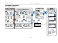
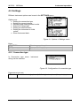
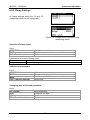
VAFMeter MI 2230 Instruction manual Version 1.2, Code no. 20 751 916 Distributor: Manufacturer: METREL d.d. Ljubljanska cesta 77 1354 Horjul Slovenia web site: http://www.metrel.si e-mail: [email protected] Mark on your equipment certifies that this equipment meets the requirements of the EU (European Union) concerning safety and electromagnetic compatibility regulations © 2011 METREL The trade name Metrel, is trademark registered or pending in Europe and other countries. No part of this publication may be reproduced or utilized in any form or by any means without permission in writing from METREL. 2 MI 2230 - VAFMeter Table of contests Table of contents 1 Preface ....................................................................................................................5 2 Safety and operational considerations.................................................................6 2.1 2.2 Warnings and notes ..........................................................................................6 Battery and charging .........................................................................................8 2.2.1 2.3 3 Instrument description.........................................................................................11 3.1 3.2 3.3 3.4 Front panel ......................................................................................................11 Connector panel ..............................................................................................12 Back side.........................................................................................................13 Display organization ........................................................................................15 3.4.1 3.4.2 3.4.3 3.4.4 3.4.5 3.4.6 3.4.7 3.5 Function selection ...........................................................................................19 Settings ...........................................................................................................20 4.2.1 4.2.2 4.2.3 4.2.4 4.2.5 4.2.6 Connection type .................................................................................................. 20 Clamp Settings.................................................................................................... 22 Memory ............................................................................................................... 23 Language ............................................................................................................ 23 Date and time...................................................................................................... 23 Initial settings ...................................................................................................... 24 Measurements ......................................................................................................25 5.1 Voltage, current, power, THD, frequency and phase sequence ......................25 5.1.1 5.1.2 5.1.3 5.1.4 5.2 UIF ...................................................................................................................... 25 PQS..................................................................................................................... 28 Vector diagram.................................................................................................... 30 THD..................................................................................................................... 31 Resistance of connections...............................................................................33 5.2.1 5.2.2 5.2.3 6 Standard set MI 2230.......................................................................................... 18 Optional accessories........................................................................................... 18 Instrument operation............................................................................................19 4.1 4.2 5 Key manipulation................................................................................................. 15 Terminal voltage monitor..................................................................................... 16 Battery indication................................................................................................. 16 Message field ...................................................................................................... 16 Result field .......................................................................................................... 17 Help screens ....................................................................................................... 17 Backlight and contrast adjustments .................................................................... 17 Instrument set and accessories.......................................................................18 3.5.1 3.5.2 4 New battery cells or cells unused for a longer period ........................................... 9 Standards applied ...........................................................................................10 R LOWΩ, 200 mA resistance measurement....................................................... 34 Continuous resistance measurement with low current........................................ 35 Compensation of test leads resistance ............................................................... 36 Data handling........................................................................................................38 6.1 6.2 6.3 Memory organization .......................................................................................38 Data structure..................................................................................................38 Storing test results...........................................................................................39 3 MI 2230 - VAFMeter 6.4 6.5 Recalling test results .......................................................................................39 Clearing stored data ........................................................................................40 6.5.1 6.5.2 6.5.3 6.5.4 6.6 7 Clearing complete memory content .................................................................... 40 Clearing measurement(s) in selected location .................................................... 41 Clearing individual measurements ...................................................................... 41 Renaming installation structure elements ........................................................... 42 Communication ...............................................................................................42 Maintenance..........................................................................................................44 7.1 7.2 7.3 7.4 7.5 8 Table of contests Fuse replacement............................................................................................44 Cleaning ..........................................................................................................44 Periodic calibration ..........................................................................................44 Service ............................................................................................................44 Upgrading the instrument ................................................................................45 Technical specifications ......................................................................................46 8.1 8.2 8.3 8.4 8.5 8.6 8.7 8.8 8.9 8.10 8.11 General data....................................................................................................46 Voltage ............................................................................................................46 Frequency* ......................................................................................................46 Current (A 1398 - 10A current clamps)............................................................47 Current (A 1395 – flex clamps)........................................................................47 Power (W, VA, Var) .........................................................................................47 Power factor - PF ............................................................................................48 Cos φ - DPF ....................................................................................................48 Phase angle ....................................................................................................48 Voltage and current THD.................................................................................48 Resistance / Continuity....................................................................................48 8.11.1 8.11.2 Resistance R LOWΩ........................................................................................... 48 Resistance CONTINUITY ................................................................................... 48 4 MI 2230 - VAFMeter Preface 1 Preface Congratulations on your purchase of the VAFMeter (Volt-Ampere-Phase-Meter) instrument and its accessories from METREL. The instrument was designed on a basis of rich experience, acquired through many years of dealing with electric installation test equipment. The VAFMeter instrument is professional, multifunctional, hand-held test instrument intended to perform measurements required in order for a total inspection of electrical installations and devices in buildings and industry. The following measurements and tests can be performed: Voltages Currents Frequency Active, reactive and apparent powers Phase angles, cos φ and power factors Resistance/Continuity tests The graphics display with backlight offers easy reading of results, indications, measurement parameters and messages. The operation of the instrument is designed to be as simple and clear as possible and no special training (except for the reading this instruction manual) is required in order to begin using the instrument. In order for operator to be familiar enough with performing measurements in general and their typical applications it is advisable to read Metrel handbook ”Modern Power Quality Measurement Techniques” The instrument is equipped with the entire necessary accessory for comfortable testing. 5 MI 2230 – VAFMeter Safety and operational considerations 2 Safety and operational considerations 2.1 Warnings and notes In order to maintain the highest level of operator safety while carrying out various tests and measurements, Metrel recommends keeping your VAFMeter instrument in good condition and undamaged. When using the instrument, consider the following general warnings: General warnings related to safety: The symbol on the instrument means »Read the Instruction manual with special care for safe operation«. The symbol requires an action! If the test equipment is used in a manner not specified in this user manual, the protection provided by the equipment could be impaired! Read this user manual carefully, otherwise the use of the instrument may be dangerous for the operator, the instrument or for the equipment under test! Do not use the instrument or any of the accessories if any damage is noticed! Consider all generally known precautions in order to avoid risk of electric shock while dealing with hazardous voltages! If a fuse blows in the instrument, follow the instructions in this manual in order to replace it! Do not use the instrument in AC supply systems with voltages higher than 600 VAC! Service, repairs or adjustment of instruments and accessories is only allowed to be carried out by competent authorized personnel! Use only standard or optional test accessories supplied by your distributor! The instrument comes supplied with rechargeable Ni-MH battery cells. The cells should only be replaced with the same type as defined on the battery compartment label or as described in this manual. Do not use standard alkaline battery cells while the power supply adapter is connected, otherwise they may explode! Hazardous voltages exist inside the instrument. Disconnect all test leads, remove the power supply cable and switch off the instrument before opening back cover! 6 MI 2230 – VAFMeter Safety and operational considerations All normal safety precautions must be taken in order to avoid risk of electric shock while working on electrical installations! Warnings related to measurement functions: Voltage, current, power, THD metering The user can browse through all sub-functions while the measurements are running. Pressing the TEST key starts/stops all sub-functions! Before starting any measurement the current Clamp settings and Connection type in Settings menu should be checked. Select appropriate current clamp model and measuring range that are best fitted to the expected current values. Consider polarity of current clamp (arrow on test clamp should be oriented toward connected load), otherwise result will be negative! Continuity functions Continuity measurements should only be performed on de-energized objects! Parallel impedances or transient currents may influence test results. 7 MI 2230 – VAFMeter Safety and operational considerations 2.2 Battery and charging The instrument uses six AA size alkaline or rechargeable Ni-MH battery cells. Nominal operating time is declared for cells with nominal capacity of 2100 mAh. Battery condition is always displayed in the lower right display part. In case the battery is too weak the instrument indicates this as shown on Figure 2.1. This indication appears for a few seconds and then the instrument turns itself off. Figure 2.1: Discharged battery indication The battery is charged whenever the power supply adapter is connected to the instrument. The power supply socket polarity is shown on Figure 2.2. Internal circuit controls charging and assures maximum battery lifetime. - + Figure 2.2: Power supply socket polarity The instrument automatically recognizes the connected power supply adapter and begins charging the batteries if they are present. Symbols: Indication of connected power supply and battery charging (if batteries are present) Figure 2.3: Charging indication When connected to an installation, the instruments battery compartment can contain hazardous voltage inside! When replacing battery cells or before opening the battery/fuse compartment cover, disconnect any measuring accessory connected to the instrument and turn off the instrument, Ensure that the battery cells are inserted correctly otherwise the instrument will not operate and the batteries could be discharged. If the instrument is not to be used for a long period of time, remove all batteries from the battery compartment. Alkaline or rechargeable Ni-MH batteries (size AA) can be used. Metrel recommends only using rechargeable batteries with a capacity of 2100mAh or above. Do not recharge alkaline battery cells! Use only power supply adapter delivered from the manufacturer or distributor of the test equipment to avoid possible fire or electric shock! 8 MI 2230 – VAFMeter Safety and operational considerations 2.2.1 New battery cells or cells unused for a longer period Unpredictable chemical processes can occur during the charging of new battery cells or cells that have been left unused for a longer period (more than 3 months). Ni-MH cells can be subjected to these chemical effects (sometimes called the memory effect). As a result the instrument operation time can be significantly reduced during the initial charging/discharging cycles of the batteries. In this situation, Metrel recommend the following procedure to improve the battery lifetime: Procedure Completely charge the battery. Notes At least 14h with in-built charger. This can be performed by using the Completely discharge the battery. instrument normally until the instrument is fully discharged. Repeat the charge / discharge cycle Four cycles are recommended in order to at least 2-4 times. restore the batteries to their normal capacity. Notes: The charger in the instrument is a pack cell charger. This means that the battery cells are connected in series during the charging. The battery cells have to be equivalent (same charge condition, same type and age). One different battery cell can cause an improper charging and incorrect discharging during normal usage of the entire battery pack (it results in heating of the battery pack, significantly decreased operation time, reversed polarity of defective cell,…). If no improvement is achieved after several charge / discharge cycles, then each battery cell should be checked (by comparing battery voltages, testing them in a cell charger, etc). It is very likely that only some of the battery cells are deteriorated. The effects described above should not be confused with the normal decrease of battery capacity over time. Battery also loses some capacity when it is repeatedly charged / discharged. Actual decreasing of capacity, versus number of charging cycles, depends on battery type. This information is provided in the technical specification from battery manufacturer. 9 MI 2230 – VAFMeter Safety and operational considerations 2.3 Standards applied The VAFMeter instrument is manufactured and tested in accordance with the following regulations: Electromagnetic compatibility (EMC) EN 61326 Electrical equipment for measurement, control and laboratory use – EMC requirements Class B (Hand-held equipment used in controlled EM environments) Safety (LVD) EN 61010-1 Safety requirements for electrical equipment for measurement, control and laboratory use – Part 1: General requirements EN 61010-2-030 Safety requirements for electrical equipment for measurement, control and laboratory use – Part 2-030: Particular requirements for testing and measuring circuits EN 61010-031 Safety requirements for hand-held probe assemblies for electrical measurement and test EN 61010-2-032 Safety requirements for electrical equipment for measurement, control, and laboratory use - Part 2-032: Particular requirements for hand-held and hand-manipulated current sensors for electrical test and measurement Functionality EN 61000-4-30 Testing and measurement techniques – Power quality measurement methods EN 61557-12 Equipment for testing, measuring or monitoring of protective measures – Part 12: Performance measuring and monitoring devices (PMD) EN 61000-4-7 General guide on harmonics and interharmonics measurements and instrumentation Note about EN and IEC standards: Text of this manual contains references to European standards. All standards of EN 6XXXX (e.g. EN 61010) series are equivalent to IEC standards with the same number (e.g. IEC 61010) and differ only in amended parts required by European harmonization procedure. 10 MI 2230 – VAFMeter Instrument description 3 Instrument description 3.1 Front panel Figure 3.1: Front panel Legend: 1 2 3 4 5 6 7 LCD UP/DOWN TEST ESC TAB Backlight, Contrast Red/Green LED 8 ON / OFF 9 HELP / CAL 10 11 Function selector MEM 128 x 64 dots matrix display with backlight. Modifies selected parameter. Starts measurements. Goes one level back. Selects the parameters in selected function. Changes backlight level and contrast. Pass / fail functionality in Continuity / R LowΩ measurements Switches the instrument power on or off. The instrument automatically turns off 15 minutes after the last key was pressed. Accesses help menus. Calibrates test leads in Continuity / R LowΩ functions. Selects test function. Store / recall / clear tests in memory of instrument. 11 MI 2230 – VAFMeter Instrument description 3.2 Connector panel Figure 3.2: Connector panel Legend: 1 Protection cover 2 Charger socket 3 USB connector 4 PS/2 connector 5 6 7 C1 C2 Test connector Communication with PC. USB (1.1) port. Communication with PC serial port and connection to optional measuring adapters. Current clamp measuring input I1 Current clamp measuring input I2 Measuring inputs / outputs Warnings! Maximum allowed voltage between any test terminal and ground is 600 V! Maximum allowed voltage between Test connector terminals is 600 V! Maximum allowed voltage between test terminals C1, C2 is 3 V! Maximum short-term voltage of external power supply adapter is 14 V! 12 MI 2230 – VAFMeter Instrument description 3.3 Back side 3 2 1 Figure 3.3: Back panel Legend: 1 2 3 Battery / fuse compartment cover Back panel information label Fixing screws for battery / fuse compartment cover 2 1 3 Fuse F2 Fuse F1 F3 Fuse SIZE AA SIZE AA SIZE AA - + + - SIZE AA 4 - + + - SIZE AA + - S/N XXXXXXXX SIZE AA + 5 Figure 3.4: Battery and fuse compartment Legend: 1 2 3 4 5 Fuse F1 Fuse F2 Fuse F3 Serial number label Battery cells M 315 mA / 250 V F 4 A / 500 V F 4 A / 500 V Size AA, alkaline / rechargeable NiMH 13 MI 2230 – VAFMeter Instrument description 2 Continuity R Low (EN 61557-4) R: 0.12 1999 Test current: min. ±200mA at 2 Open-circuit voltage: 6.5V 9.0V Continuity 7mA R: 0.0 1999 Test current: max. 8.5mA Open-circuit voltage: 6.5V Insulation resistance (EN 61557-2) R: 0.18M 199.9M , UN=50V ,100 V , 250V R: 0.12M 999M , UN = 500V, 1kV U: 0V 1200V Nominal voltages: 100V, 250V, 500V, 1kV Measuring current: min. 1mA at RN =UN 1k /V Short-circuit current: < 3mA Line impedance (EN 61557-3) R L-N (L): 0. 17 1999 I PSC: 0. 20A Nominal voltage: 100V 440V / 15Hz 1. 4kA 500Hz Fault loop impedance (EN 61557-3) R L-PE : 0.17 1999 IPFC : 0. 14A 1. 4kA Nominal voltage: 100V 264V / 15Hz 500Hz Voltage, frequency U: 0V 440V / f: 15Hz RCD (EN 61557-6) I : 10mA, 30mA, 100mA, 300mA, 500mA, 1A Nominal voltage: 100V 264V / 15Hz 500Hz Contact voltage U C : 0.0V 100.0V R S : 0.00 10.00k (R S=U C / I N) Tripping time non-delayed (time-delayed) RCDs 1: 0ms 300ms (500ms) 2 : 0ms 150ms (200ms) 5 : 0ms 40ms (150ms), UC : 0.0V 100.0V Tripping current I : 0.2 I N 1.1 I N AC ( 1.5 I N A) t : 0ms 300ms, UC : 0.0V 100.0V Multiplier: 0.5, 1, 2, 5 20 224 832 3 1 Resistance to earth (EN 61557-5) R : 0.04 9999 Open-circuit voltage : < 45VRMS Short-circuit current : < 20mA CAT III 600V 500Hz Phase rotation (EN 61557-7) Nominal voltage: 100V 440V / 1 5Hz Results: 1.2.3 or 2.1.3 500 Hz Figure 3.5: Bottom Legend: 1 2 3 Bottom information label Neck belt openings Handling side covers 14 550V Ljubljanska 77 SI - 1354 Horjul Tel: +386 1 75 58 200 http://www.metrel.si MI 2230 - VAFMeter Instrument description 3.4 Display organization 3.4.1 Key manipulation 15 MI 2230 - VAFMeter Instrument description Function name Result field Label field Battery and charger indication Figure 3.6: Typical function display Function name Result field Message field Terminal voltage monitor Battery and charger indication Figure 3.7: Typical function display 3.4.2 Terminal voltage monitor The terminal voltage monitor displays on-line the voltages on the test terminals and information about active test terminals. Online voltages are displayed together with test terminal indication. L2+ and L1- test terminals are used for selected measurement. 3.4.3 Battery indication The indication indicates the charge condition of battery and connection of external charger. Battery capacity indication. Low battery. Battery is too weak to guarantee correct result. Replace or recharge the battery cells. 3.4.4 Message field In the message field warnings and messages are displayed. Measurement is running. Conditions on the input terminals allow starting the measurement; consider other displayed warnings and messages. Conditions on the input terminals do not allow starting the measurement; consider displayed warnings and messages. 16 MI 2230 – VAFMeter Instrument description Result(s) can be stored. Test leads resistance in R LowΩ and Continuity measurement is not compensated. Test leads resistance in R LowΩ and Continuity measurement is compensated. Fuse F1 broken. 3.4.5 Result field Measurement result is inside pre-set limits (PASS). Measurement result is out of pre-set limits (FAIL). Measurement is aborted. Consider displayed warnings and messages. 3.4.6 Help screens HELP Opens help screen. The Help menu contains schematic diagrams for illustrating how to properly connect the instrument to electric installation. After selecting the measurement you want to perform, press the HELP key in order to view the associated Help menu. Help menus is not available in LowΩ / Continuity functions, as HELP key is used for calibration. Keys in help menu: UP / DOWN TAB ESC / Function selector Selects next / previous help screen. Scrolls through help screens. Exits help menu. Figure 3.8: Examples of help screens 3.4.7 Backlight and contrast adjustments With the BACKLIGHT key backlight and contrast can be adjusted. Toggles backlight intensity level. Locks high intensity backlight level until power is turned off or the Keep pressed for 1 s key is pressed again. Keep pressed for 2 s Bargraph for LCD contrast adjustment is displayed. Click 17 MI 2230 – VAFMeter Instrument description Figure 3.9: Contrast adjustment menu Keys for contrast adjustment: DOWN UP TEST Reduces contrast. Increases contrast. Accepts new contrast. 3.5 Instrument set and accessories 3.5.1 Standard set MI 2230 Instrument Instruction manual Calibration Certificate Test lead 4 x 1.5 m Test probe, 4 pcs Two A 1398 - 10 A current clamps Crocodile clip, 4 pcs Set of NiMH battery cells Power supply adapter CD with instruction manual, EuroLink Software and “Modern Power Quality Measurement Techniques” handbook. Set of carrying straps 3.5.2 Optional accessories See the attached sheet for a list of optional accessories that are available on request from your distributor. 18 MI 2230 – VAFMeter Instrument operation 4 Instrument operation 4.1 Function selection For selecting test function the FUNCTION SELECTOR shall be used. Keys: Select test / measurement function: FUNCTION SELECTOR UP/DOWN TAB TEST MEM ESC <VAF> Voltage and frequency, phase sequence, power, THD. <R LOWΩ> Resistance of earth connections and bondings. <SETTINGS> General instrument settings. Selects sub-function in selected measurement function. Selects the test parameter to be set or modified. Selects screen to be viewed (if results are split into more screens). Runs selected test / measurement function. Stores measured results / recalls stored results. Returns back to higher levels. Keys in test parameter field: Changes the selected parameter. UP/DOWN Selects the next measuring parameter. TAB Toggles between the main functions. Function selector Stores measured results / recalls stored results. MEM General rule regarding enabling parameters for evaluation of measurement / test result: No limit values, indication: _ _ _. OFF Parameter Value(s) – results will be marked as PASS or FAIL in ON accordance with selected limit. See chapter 5 for more information about the operation of the instrument test functions. 19 MI 2230 - VAFMeter Instrument operation 4.2 Settings Different instrument options can be set in the SETTINGS menu. Options are: Setting the connection type, Setting the current clamps, Recalling and clearing stored results Selection of language, Setting the date and time, Setting the instrument to initial values, Show Instrument data. Figure 4.1: Options in Settings menu Keys: UP / DOWN TEST Function selector Selects appropriate option. Enters selected option. Exits back to main function menu. 4.2.1 Connection type In Connection type menu, instrument wiring can be selected. Figure 4.2: Configuration of connection type Parameters to be set: Connection in single phase (L1, I1 only) or two phase (four-poles) systems 2 Phase 20 MI 2230 – VAFMeter Instrument operation L N L1+ I1 L' Device Under Test N' L2- L1- L2+ Figure 4.3: 2 phase connection 3 Phase (Aaron) Connection in three-phase, three wire system Figure 4.4: 3 phase (Aaron) connection Keys: UP / DOWN TEST ESC / Function selector Selects appropriate option. Confirms selection. Exits back without confirmation. 21 I2 MI 2230 – VAFMeter Instrument operation 4.2.2 Clamp Settings In Clamp settings menu the C1 and C2 measuring inputs can be configured. Figure 4.5: Configuration of current clamp measuring inputs Selection of clamp input Keys: UP / DOWN TEST ESC / Function selector Selects current clamp measuring input. Enters clamp menu. Exits back. Parameters to be set in Clamp menu: Model of current clamp. Model Measuring range of current clamp. Range Selection of parameters Keys: UP / DOWN TEST MEM ESC / Function selector Selects appropriate option. Enables changing data of selected parameter. Confirms selection. Exits back. Changing data of selected parameter Keys: UP / DOWN TEST MEM ESC / Function selector Sets parameter. Confirms set data. Confirms selection. Exits back. 22 MI 2230 – VAFMeter Instrument operation 4.2.3 Memory In this menu the stored data can be recalled and deleted. See chapter 6 Data handling for more information. Figure 4.6: Memory menu Keys: UP / DOWN TEST ESC / Function selector Selects option. Enters selected option. Exits back. 4.2.4 Language In this menu the language can be set. Figure 4.7: Language selection Keys: UP / DOWN TEST ESC / Function selector Selects language. Confirms selected language and exits to settings menu. Exits back without confirmation. 4.2.5 Date and time In this menu date and time can be set. Figure 4.8: Setting date and time Keys: TAB UP / DOWN TEST ESC / Function selector Selects the field to be changed. Modifies selected field. Confirms new setup and exits. Exits back without confirmation. 23 MI 2230 – VAFMeter Instrument operation Warning: If the batteries are removed for more than 1 minute the set time and date will be lost. 4.2.6 Initial settings In this menu the instrument settings and measurement parameters and limits can be set to initial (factory) values. Figure 4.9: Initial settings dialogue Keys: UP / DOWN TEST ESC / Function selector Selects YES or NO. Restores default settings (if YES selected). Exits back without changes (if NO selected). Exits back without changes. Warning: Customized settings will be lost when this option is used! If the batteries are removed for more than 1 minute the custom made settings will also be lost. The default setup is listed below: Instrument setting Contrast Language Clamp settings: Connection type: Function Sub-function Low Ohm Resistance R LOW CONTINUITY Default value As defined and stored by adjustment procedure English Model: A1398 Range: 10 A 2 phase Parameters / limit value No limit No limit Note: Initial settings (reset of the instrument) can be recalled also if the TAB key is pressed while the instrument is switched on. 24 MI 2230 - VAFMeter Measurements 5 Measurements 5.1 Voltage, current, power, THD, frequency and phase sequence 5.1.1 UIF UIF screen shows RMS (root means square) voltages, currents and phase angles which are measured by the instrument. Instrument show relevant measurements for chosen connection type: 2-phase or 3-phase (Aaron) system. UIF measurement procedure Select appropriate connection type (see chapter: 4.2.1 Connection type). Configure clamp settings if needed (see chapter: 4.2.2 Clamp Settings). Select the UIF sub-function using function selector and UP/DOWN keys. Measurements will start automatically. Connect test lead and current clamps to the instrument. Connect test lead to the item to be measured (see Figure 4.3 and Figure 4.4). Embrace wires where current should be measured. Press the TEST key again to stop the measurement. All sub-functions will stop. Store voltage measurement result by pressing the MEM key (optional). Press the TEST key to start again the measurement. All sub-functions will start. Figure 5.1: UIf measurement in 2-phase system Displayed results for 2-phase system: U1 ............RMS Voltage between L1+ and L1- conductors, U2 ............RMS Voltage between L2+ and L2- conductors, I1 ..............Current measured on I1 current clamps. I2 ..............Current measured on I2 current clamps. φU1-I1 ........Phase angle between voltage U1 and current I1 fundamentals φU2-I2 ........Phase angle between voltage U2 and current I2 fundamentals f ...............Frequency of voltage U1. If U1 is to low, frequency of I1 is shown. φU-U..........Phase angle between voltages U1 and U2 φI-I ............Phase angle between currents I1 and I2 Figure 5.2: UIf measurement in 3-phase (Aaron) system 25 MI 2230 – VAFMeter Measurements Displayed results for three-phase (Aaron) system: U12..........Measured voltage between phases L1 and L2, U23..........Measured voltage between phases L2 and L3, U31..........Calculated voltage between phases L3 and L1, I12 ............Measured current I1 on phase L1. I23 ............Current calculated I2 on phase L2. I31 ............Measured current I3 on phase L3. φU12 .........Phase angle of voltage U12 φU23 .........Phase angle of voltage U23 φU31 .........Phase angle of voltage U31 φI12 ..........Phase angle of current I12 on phase L1. φI23 ..........Phase angle of current I23 on phase L2. φI31 ..........Phase angle of current I31 on phase L3. f ...............Frequency of voltage U12. If U12 is to low, freq. of current on phase L1 is shown. Keys: Function selector UP/DOWN TAB TEST MEM Toggles between the main functions. Toggles between sub-functions. Toggles between multiple result screens. Starts / stops the measurement. Stores measured results / recalls stored results. All voltage and current measurements represents RMS values of 512 samples of the voltage magnitude over a 10-cycle time interval. Voltage values are measured according to the following equation: Phase voltage: Up Phase to phase voltage: Upg 1 1024 2 up 1024 j 1 j [V], p: 1,2 1 1024 (u p j u g j ) 2 [V], pg: 12,23,31 1024 j 1 (1) (2) The instrument has 7 voltage ranges internally, which are switched automatically, regarding the measured voltage. Current values are measured according to the following equation: Phase current: Ip 1 1024 2 Ip 1024 j 1 j [A], p: 1,2 (3) The instrument has 4 current ranges internally, which are switched automatically, regarding the measured current. Measurement of phase angles is performed on fundamental components of current and voltage. Synchronization channel (voltage U1, U12 or current I1) is drawn on positive xaxis, and has angle zero. In 2-phase connection, phase angles are measured between 26 MI 2230 – VAFMeter Measurements voltage and current, voltages U1 and U2, and currents I1 and I2, according to the figure and formulas bellow. 90' I1 L1- U1 L1+ I2 L2+ U2 U2 I1 φUI2 L2- φU-U φUI1 φI-I U1 I2 Voltage to current phase angle: UIp (U p ) ( I p ) 0' [0], p: 1,2 Voltage to voltage phase angle: U U (U 1 ) (U 2 ) [0] Current to current phase angle: φ I I ( I 1 ) ( I 2 ) [ 0] (4) (5) (6) Load U31 U23 U12 In 3-phase (Aaron) connection, angles shown on instrument represents voltage and current angles of voltages and current vectors in vector diagram. Synchronization channel (voltage U12 or current I1) is drawn on positive x-axis, and has angle zero. Figure bellow graphically represents phase angles values and its meanings. Voltage phase angle: Upg (U pg ) [0], pg: 12, 23, 31 (7) Current phase angle: Ip ( I p ) [0], p: 1, 2, 3 (8) 27 MI 2230 – VAFMeter Measurements Frequency reading is obtained from 10 cycles, as ratio of 10 cycles and the duration of the integer cycles. Frequency: f 10 [Hz] duration _ of _ 10 _ cycles (9) 5.1.2 PQS In this sub-function standard 2-phase and 3-phase (Aaron) power measurements can be performed with the instrument. PQS measurement procedure Select appropriate connection type (see chapter: 4.2.1 Connection type). Configure clamp settings if needed (see chapter: 4.2.2 Clamp Settings). Select PQS sub-function using function selector and UP/DOWN keys. Measurements will start automatically. Connect test lead and current clamps to the instrument. Connect test lead to the item to be measured (see Figure 4.3 and Figure 4.4). Embrace wires where current should be measured. Press the TEST key to stop the measurement. All sub-functions will stop. Store the result by pressing the MEM key (optional). Press the TEST key again to start the measurement. All sub-functions will start. Figure 5.3: Power measurement in 2-phase system Displayed results for 2-phase system: P1 ............Active power on L1 channel P2 ............Active power on L2 channel Q1 ............Reactive power on L1 channel Q2 ............Reactive power on L2 channel S1 ............Apparent power on L1 channel S2 ............Apparent power on L2 channel PF1 ..........Power factor on L1 channel PF2 ..........Power factor on L2 channel DPF1 ........Displacement power factor (Cosφ1) on L1 channel DPF2 ........Displacement power factor (Cosφ2) on L2 channel 28 MI 2230 – VAFMeter Measurements Figure 5.4: Power measurements in 3-phase (Aaron) system Displayed results for 3-phase (Aaron) system: Ptot ...........Total active power Qtot ...........Total reactive power Stot ...........Total apparent power PFtot .........Total Power factor Keys: Function selector UP/DOWN TEST MEM Toggles between the main functions. Toggles between sub-functions. Starts / stops the measurement. Stores measured results / recalls stored results. All active power measurements represent RMS values of the 512 samples of instantaneous power over a 10-cycle time interval. Phase active power: 1 1024 1 1024 Pp pp j U p I p j 1024 j 1 1024 j 1 j (10) [W], p: 1,2 Apparent and reactive power, power factor and displacement power factor (Cos φ) are calculated according to the following equations: Phase apparent power: Sp U p I p Phase reactive power: Q p Sign(Q p ) * S p2 Pp2 Sign of reactive power: 1, p 0 0 180 0 Sign(Q p ) 0 0 1, p 0 180 Phase power factor: DPF (Cos φ): [VA], p: 1,2 PFp Pp Sp (11) [VAr], p: 1,2 , p: 1,2 Cos p Cos ( u p i p ) , p: 1,2 p: 1,2 (12) (13) (14) (15) Total active, reactive and apparent power and total power factor are calculated according to the following equations: Total active power: Pt P1 P 2 [W], 29 (16) MI 2230 – VAFMeter Measurements Total reactive power (vector): Qt Q1 Q 2 [VAr], Total apparent power (vector): St Total power factor (vector): PFtot Pt 2 Qt 2 [VA], (18) (19) Generated reactive Power Consumed reactive Power Pt . St (17) Figure 5.5: Vector representation of 4-quadrand power calculus 5.1.3 Vector diagram Vector diagram shows angles of voltages and current vectors in degrees. Instrument shows relevant measurements for chosen connection type: 2-phase or 3-phase (Aaron) system. Vector diagram measurement procedure Select appropriate connection type (see chapter: 4.2.1 Connection type). Configure clamp settings if needed (see chapter: 4.2.2 Clamp Settings). Select the VECT sub-function using function selector and UP/DOWN keys. Measurements will start automatically. Connect test lead and current clamps to the instrument. Connect test lead to the item to be measured (see Figure 4.3 and Figure 4.4). Embrace wires where current should be measured. Press the TEST key to stop the measurement. All sub-functions will stop. Store the result by pressing the MEM key (optional). Press the TEST key again to start the measurement. All sub-functions will start. 30 MI 2230 – VAFMeter Measurements Figure 5.6: Vector diagram in 2-phase system Displayed results for 2-phase system: U1 ............Phase angle of voltage vector U1 U2 ............Phase angle of voltage vector U2 I1 ..............Phase angle of current vector I1 I2 ..............Phase angle of current vector I2 Figure 5.7: Vector diagram in 3-phase (Aaron) system Displayed results for 3-phase (Aaron) system: U12 ...........Phase angle of voltage vector U12 U23 ...........Phase angle of voltage vector U23 U31 ...........Phase angle of voltage vector U31 I1 ..............Phase angle of current vector I1 I2 ..............Phase angle of current vector I2 I3 ..............Phase angle of current vector I3 Keys: Function selector UP/DOWN TAB TEST MEM Toggles between the main functions. Toggles between sub-functions. Toggles between multiple result screens. Starts / stops the measurement. Stores measured results / recalls stored results. Vector angles are obtained from Fourier transform, which is performed on 10-cycle, 512 samples long samples stream. For detailed explanation about angles calculus see chapter 5.1.1. 5.1.4 THD THD screen shows THD (total harmonic distortion) of voltages, currents which are measured by the instrument. Instrument shows relevant measurements according to the connection type: two-phase or three phase (Aaron) system. THD measurement procedure Select appropriate connection type (see chapter: 4.2.1 Connection type). Configure clamp settings if needed (see chapter: 4.2.2 Clamp Settings). Select the THD sub-function using function selector and UP/DOWN keys. 31 MI 2230 – VAFMeter Measurements Measurements will start automatically. Connect test lead and current clamps to the instrument. Connect test lead to the item to be measured (see Figure 4.3 and Figure 4.4). Embrace wires where current should be measured. Press the TEST key to stop the measurement. All sub-functions will stop. Store the result by pressing the MEM key (optional). Press the TEST key again to start the measurement. All sub-functions will start. Figure 5.8: THD measurement in 2-phase system Displayed results for 2-phase system: thdU1(%)..Total harmonic distortion of U1 expressed in percent of first harmonic thdU1(V) ..Total harmonic distortion of U1 expressed in volts thdU2(%)..Total harmonic distortion of U2 expressed in percent of first harmonic thdU2(V) ..Total harmonic distortion of U2 expressed in volts thdI1(%) ...Total harmonic distortion of I1 expressed in percent of first harmonic thdI1(A) ....Total harmonic distortion of I1 expressed in volts thdI2(%) ...Total harmonic distortion of I1 expressed in percent of first harmonic thdI2(A) ....Total harmonic distortion of I1 expressed in volts Figure 5.9: THD measurement in 3-phase (Aaron) system Displayed results for three-phase (Aaron) system: thdU12(%) Total harmonic distortion of U12 expressed in percent of first harmonic thdU12(V) .Total harmonic distortion of U11 expressed in volts thdU23(%) Total harmonic distortion of U23 expressed in percent of first harmonic thdU23(V) .Total harmonic distortion of U23 expressed in volts thdU31(%) Total harmonic distortion of U31 expressed in percent of first harmonic thdU31(V) .Total harmonic distortion of U31 expressed in volts thdI12(%) ..Total harmonic distortion of current I1 on L1 in percent of first harmonic thdI12(A)...Total harmonic distortion of current I1 on L2 in amperes. thdI23(%) ..Total harmonic distortion of current I2 on L2 in percent of first harmonic thdI23(A)...Total harmonic distortion of current I2 on L2 in amperes. thdI31(%) ..Total harmonic distortion of current I3 on L3 in percent of first harmonic thdI31(A)...Total harmonic distortion of current I3 on L3 in amperes. Keys: Function selector Toggles between the main functions. 32 MI 2230 – VAFMeter UP/DOWN TAB TEST MEM Measurements Toggles between sub-functions. Toggles between multiple result screens. Starts / stops the measurement. Stores measured results / recalls stored results. Total harmonic distortion is calculated according to the following calculus: Total voltage harmonic distortion (%): THDU p U p hn n 2 U p h1 Total voltage harmonic distortion (V): THDU p 25 n2 2 , p: 1,2,3 (21) 2 25 n2 , p: 1,2,3 p n I p hn Total current harmonic distortion(%): THDIp n 2 I p h1 I (20) 2 U h 25 25 Total current harmonic distortion(A): THDIp 2 , p: 1,2,3 h p n , p: 1,2,3 (22) 5.2 Resistance of connections The resistance measurement is performed in order to ensure good bonding and joints. Two sub-functions are available: R LOWΩ - Earth bond resistance measurement according to EN 61557-4 (200 mA) CONTINUITY - Continuous resistance measurement performed with 7 mA Figure 5.10: 200 mA RLOW Ω screen Test parameters for resistance measurement TEST Resistance measurement sub-function [R LOWΩ, CONTINUITY] Limit Maximum resistance [OFF, 0.1 ÷ 20.0 ] Keys in test parameter field: Selects the test parameter to be set or modified. TAB Selects test parameter value. UP/DOWN 33 MI 2230 – VAFMeter Measurements 5.2.1 R LOWΩ, 200 mA resistance measurement The resistance measurement is performed with automatic polarity reversal of the test voltage. Test circuit for R LOWΩ measurement L1+ Junction L1- Figure 5.11: Junction resistance measurement example Resistance measurement procedure Select R LOWΩ sub-function using the function selector and UP/DOWN keys. Enable and set limit (optional). Connect test lead to the instrument. Compensate the test leads resistance (if necessary, see chapter 5.2.3). Disconnect from mains supply and discharge the object to be tested. Connect the test leads L1+ and L1- to the tested object (see Figure 5.11). Press the TEST key to perform the measurement. After the measurement is finished store the result by pressing the MEM button (optional). Figure 5.12: Example of RLOW result Displayed results: R................R LOWΩ resistance. R+..............Result at positive test polarity R-...............Result at negative test polarity 34 MI 2230 - VAFMeter Keys: Function selector UP/DOWN TAB TEST MEM Measurements Toggles between the main functions. Toggles between sub-functions. Selects the test parameter value. Selects the test parameter field. Starts the measurement. Stores measured results / recalls stored results. 5.2.2 Continuous resistance measurement with low current In general, this function serves as standard -meter with a low testing current. The measurement is performed continuously without polarity reversal. The function can also be applied for testing continuity of inductive components. Test circuit for continuous resistance measurement L1+ L1- Figure 5.13: 2-wire test lead application Continuous resistance measurement procedure Select CONTINUITY sub-function using the function selector and UP/DOWN keys. Enable and set limit (optional). Connect test lead to the instrument. Compensate the test leads resistance (if necessary, see chapter 5.2.3). Disconnect from mains supply and discharge the object to be tested. Connect the test leads L1+ and L1- to the tested object (see Figure 5.13). Press the TEST key to begin performing a continuous measurement. Press the TEST key to stop measurement. Store the result (optional). Figure 5.14: Example of continuous resistance measurement 35 MI 2230 – VAFMeter Measurements Displayed result: R............Resistance Keys: Function selector UP/DOWN TAB TEST MEM Toggles between the main functions. Toggles between sub-functions. Selects the test parameter value. Selects the test parameter field. Starts / stops the measurement. Stores measured results / recalls stored results. Note: Continuous buzzer sound indicates that measured resistance is less than 2 . 5.2.3 Compensation of test leads resistance This chapter describes how to compensate the test leads resistance in R LOWΩ and CONTINUITY sub-functions. Compensation is required to eliminate the influence of test leads resistance and the internal resistances of the instrument on the measured resistance. The lead compensation is therefore a very important feature to obtain correct result. symbol is displayed if the compensation was carried out successfully. Circuit for compensating the resistance of test leads L1+ L1- Figure 5.15: Shorted test leads Compensation of test leads resistance procedure Select R LOWΩ or CONTINUITY function. Connect test cable to the instrument and short the L1+ and L1- test leads together (see Figure 5.15). Press the HELP/CAL key to compensate leads resistance. Press TEST to verify compensation. 36 MI 2230 – VAFMeter Measurements Displayed results: ............Test leads compensated ...........Test leads not compensated Key: HELP/CAL Starts compensation of test leads resistance procedure. Figure 5.16: Result with old calibration value Figure 5.17: Result with new calibration value Note: The highest value for lead compensation is 5 . If the resistance is higher the compensation value is set back to default value. is displayed if no calibration value is stored. 37 MI 2230 – VAFMeter Data handling 6 Data handling 6.1 Memory organization Measurement results together with all relevant parameters can be stored in the instrument’s memory. After the measurement is completed, results can be stored to the flash memory of the instrument, together with the sub-results and function parameters. 6.2 Data structure The instrument’s memory place is divided into 3 levels each containing 199 locations. The number of measurements that can be stored into one location is not limited. The data structure field describes the location of the measurement (which object, block, fuse) and where can be accessed. In the measurement field there is information about type and number of measurements that belong to the selected structure element (object and block and fuse). The main advantages of this system are: Test results can be organized and grouped in a structured manner that reflects the structure of typical electrical installations. Customized names of data structure elements can be uploaded from EurolinkPRO PCSW. Simple browsing through structure and results. Test reports can be created with no or little modifications after downloading results to a PC. Figure 6.1: Data structure and measurement fields Data structure field Memory operation menu Data structure field 1st level: OBJECT: Default location name (object and its successive number). nd 2 level: BLOCK: Default location name (block and its successive number). rd 3 level: FUSE: Default location name (fuse and its successive number). 001: No. of selected element. No. of measurements in selected location [No. of measurements in selected location and its sublocations] 38 MI 2230 – VAFMeter Data handling Measurement field Type of stored measurement in the selected location. No. of selected test result / No. of all stored test results in selected location. 6.3 Storing test results After the completion of a test the results and parameters are ready for storing ( icon is displayed in the information field). By pressing the MEM key, the user can store the results. Figure 6.2: Save test menu Memory available for storing results. Keys in save test menu: TAB UP / DOWN MEM / TEST Function selector / ESC Selects the location element (Object / Block / Fuse) Selects number of selected location element (1 to 199) Saves test results to the selected location. Exits back without saving. Notes: The instrument offers to store the result to the last selected location by default. If the measurement is to be stored to the same location as the previous one just press the MEM key twice. 6.4 Recalling test results Press the MEM key in measurement sub-functions when there is no result available for storing or select MEMORY in the SETTINGS menu. Figure 6.3: Recall menu - structure field selected Figure 6.4: Recall menu - measurements field selected Keys in recall memory menu (structure field selected): Selects the location element (Object / Block / Fuse). TAB Selects number of selected location element (1 to 199). UP / DOWN Enters measurements field. TEST / MEM Function selector / ESC Exits back. 39 MI 2230 – VAFMeter Data handling Keys in recall memory menu (measurements field selected): Selects the stored measurement. UP / DOWN View selected measurement results. TEST / MEM Returns to installation structure field. TAB / ESC Exits back. Function selector Figure 6.5: Example of recalled measurement result Keys in recall memory menu (measurement results are displayed): Toogles between multiple result screens. HELP Returns to measurements field. TEST / MEM Function selector / ESC Exits back. 6.5 Clearing stored data 6.5.1 Clearing complete memory content Select CLEAR ALL MEMORY in MEMORY menu. A warning will be displayed. Figure 6.6: Clear all memory menu Keys in clear all memory menu: Selects YES or NO. UP / DOWN Confirms clearing memory (if YES is selected) TEST Exits back without changes (if NO is selected). Function selector / ESC Exits back without changes. Figure 6.7: Clearing memory in progress 40 MI 2230 – VAFMeter Data handling 6.5.2 Clearing measurement(s) in selected location Select DELETE RESULTS in MEMORY menu. Figure 6.8: Clear measurements menu (data structure field selected) Keys in delete results menu (structure field selected): Selects the location element (Object / Block / Fuse). TAB Selects number of selected location element (1 to 199). UP / DOWN Enters dialog box for deleting all measurements in selected TEST location and its sub-locations. Function selector / ESC Exits back without changes. Enters measurements field for deleting individual MEM measurements. Keys in dialog for confirmation to clear results in selected location: Deletes all results in selected location. TEST Function selector / ESC Exits back without changes. 6.5.3 Clearing individual measurements Select DELETE RESULTS in MEMORY menu. Figure 6.9: Menu for clearing individual measurement (structure field selected) Keys in delete results menu (structure field selected): Selects the location element (Object / Block / Fuse). TAB Selects number of selected location element (1 to 199). UP / DOWN Enters measurements field for deleting individual MEM measurements. Function selector / ESC Exits back without changes. Keys in delete results menu (measurements field selected): Selects measurement. UP / DOWN Enters dialog box for deleting individual measurement. TEST Returns to structure field. TAB / ESC Exits back without changes. Function selector 41 MI 2230 – VAFMeter Data handling Keys in dialog for confirmation to clear selected result(s): Deletes selected measurement result. TEST Function selector / ESC Exits back without changes. Figure 6.11: Display after measurement was cleared Figure 6.10: Dialog for confirmation 6.5.4 Renaming installation structure elements Default structure elements are ‘Object’, ‘Block’ and ‘Fuse’. In the PCSW package Eurolink-PRO default names can be changed with customized names that corresponds the measured object. Refer to PCSW Eurolink-PRO HELP menu for information how to upload customized names structure to the instrument. Figure 6.12: Example of menu with customized installation structure names 6.6 Communication Stored results can be transferred to a PC. A special communication program on the PC automatically identifies the instrument and enables data transfer between the instrument and the PC. There are two communication interfaces available on the instrument: USB or RS 232. The instrument automatically selects the communication mode according to detected interface. USB interface has priority. Figure 6.13: Interface connection for data transfer over PC COM port 42 MI 2230 – VAFMeter Data handling How to transfer stored data: RS 232 communication: connect a PC COM port to the instrument PS/2 connector using the PS/2 - RS232 serial communication cable; USB communication: connect a PC USB port to the instrument USB connector using the USB interface cable. Switch on the PC and the instrument. Run the EurolinkPRO program. The PC and the instrument will automatically recognize each other. The instrument is prepared to download data to the PC. The program EurolinkPRO is a PC software running on Windows XP, Windows Vista and Windows 7. Read the file README_EuroLink.txt on CD for instructions about installing and running the program. Note: USB drivers should be installed on PC before using the USB interface. Refer to USB installation instructions available on installation CD. 43 MI 2230 – VAFMeter Maintenance 7 Maintenance Unauthorized persons are not allowed to open the VAFMeter instrument. There are no user replaceable components inside the instrument, except the battery and fuse under rear cover. 7.1 Fuse replacement There is a fuse under back cover of the instrument. F1 M 0.315 A / 250 V, 205 mm This fuse protects internal circuitry for continuity functions if test probes are connected to the mains supply voltage by mistake during measurement. F2 F 4 A / 500 V, 326 mm This fuse protects internal circuitry for continuity functions if test probes are connected to the mains supply voltage by mistake during measurement. F3 F 4 A / 500 V, 326 mm This fuse protects internal circuitry for continuity functions if test probes are connected to the mains supply voltage by mistake during measurement. Warnings: Disconnect all measuring accessory and switch off the instrument before opening battery / fuse compartment cover, hazardous voltage inside! Replace blown fuse with original type only, otherwise the instrument may be damaged and/or operator’s safety impaired! Position of fuse can be seen in Figure 3.6 in chapter 3.3 Back side 7.2 Cleaning No special maintenance is required for the housing. To clean the surface of the instrument use a soft cloth slightly moistened with soapy water or alcohol. Then leave the instrument to dry totally before use. Warnings: Do not use liquids based on petrol or hydrocarbons! Do not spill cleaning liquid over the instrument! 7.3 Periodic calibration It is essential that the test instrument is regularly calibrated in order that the technical specification listed in this manual is guaranteed. We recommend an annual calibration. Only an authorized technical person can do the calibration. Please contact your dealer for further information. 7.4 Service For repairs under warranty, or at any other time, please contact your distributor. 44 MI 2230 – VAFMeter Maintenance 7.5 Upgrading the instrument The instrument can be upgraded from a PC via the RS 232 communication port. This enables to keep the instrument up to date even if the standards or regulations change. The upgrade can be carried with a help of special upgrading software and the communication cable as shown on Figure 6.13. Please contact your dealer for more information. 45 MI 2230 - VAFMeter Technical specifications 8 Technical specifications 8.1 General data Power supply voltage........................ 9 VDC (61.5 V battery or accu, size AA) Operation.......................................... typical 20 h Charger socket input voltage ............ 12 V 10 % Charger socket input current ............ 400 mA max. Battery charging current ................... 250 mA (internally regulated) Overvoltage category........................ 600 V CAT II Protection classification .................... double insulation Pollution degree................................ 2 Protection degree ............................. IP 40 Display ............................................ 128x64 dots matrix display with backlight Dimensions (w h d) ..................... 23 cm 10,3 cm 11,5 cm Weight ............................................ 1.0 kg, without battery cells Reference conditions Reference temperature range........... 10 C 30 C Reference humidity range................. 40 %RH 70 %RH Operation conditions Working temperature range .............. -10 C 50 C Maximum relative humidity ............... 95 %RH (0 C 40 C), non-condensing Storage conditions Temperature range ........................... -10 C +70 C Maximum relative humidity ............... 90 %RH (-10 C +40 C) 80 %RH (40 C 60 C) The error in operating conditions could be at most the error for reference conditions (specified in the manual for each function) +1 % of measured value + 1 digit, unless otherwise specified in the manual for particular function. 8.2 Voltage Measuring range (V) Resolution (V) Accuracy 0.1 10.0 600.0 (0,5 % of reading + 3 digits) Crest factor 1.4 Result type........................................ True r.m.s. (trms) Input impedance ............................... 8.8 M Nominal frequency range.................. DC, 45 Hz 65 Hz 8.3 Frequency* Measuring range (Hz) 45.00 65.00 Resolution (Hz) 0.01 46 Accuracy 20 mHz MI 2230 – VAFMeter Technical specifications *Frequency is measured on voltage channel L1, if present. Otherwise frequency of current channel I1 is measured. 8.4 Current (A 1398 - 10A current clamps) Measuring range (A) 50.0 m 99 m 100 m 999 m 1.000 9.999 10.00 19.99 Resolution (mA) 1 1 1 10 Accuracy (1,5 % of reading + 5 digits) ( 1,5 % of reading + 2 digits) ( 1,5 % of reading + 2 digits) ( 1,5 % of reading + 2 digits) Result type........................................ True r.m.s. (trms) Input resistance ................................ 10 8.5 Current (A 1395 – flex clamps) Clamp Measuring range (A) Range 30 A 3.0 29.9 A 300 A 30.0 ÷ 299.9 A 3000 A 300.0 A ÷ 999.9 A 1000 A ÷ 6000 A Resolution (A) Accuracy 0.1 A 0.1 A 0.1 1A ( 3 % of reading + 2 digits) ( 3 % of reading + 2 digits) ( 3 % of reading + 2 digits) Result type........................................ True r.m.s. (trms) Input resistance ................................ 27 k 8.6 Power (W, VA, Var) Measuring range (W, VAr, VA) Active power P Excluding clamps With A 1398 Clamps 10A With A 1395 30/300/3000 A Reactive power Q Excluding clamps With A 1398 Clamps 10A With A 1395 30/300/3000 A Apparent power S Excluding clamps With A 1398 Clamps 10A With A 1395 30/300/3000 A Resolution 0.000 k ÷ 9999 k 0.000 k ÷ 9999 k ±(1.5 % of rdg. + 4 digts) 4 digits 0.000 k ÷ 9999 k ±(1.5 % of rdg. + 4 digts) 4 digits 0.000 k ÷ 9999 k 0.000 k ÷ 9999 k 47 ±(2 % of rdg. + 4 digts) ±(3.5 % of rdg. + 4 digts) 0.000 k ÷ 9999 k 0.000 k ÷ 9999 k ±(2 % of rdg. + 4 digts) ±(3.5 % of rdg. + 4 digts) 0.000 k ÷ 9999 k 0.000 k ÷ 9999 k Accuracy ±(1.5 % of rdg. + 4 digts) 4 digits ±(2 % of rdg. + 4 digts) ±(3.5 % of rdg. + 4 digts) MI 2230 – VAFMeter Technical specifications 8.7 Power factor - PF Measuring range -1.00 ÷ 1.00 Resolution 0.01 Accuracy ± 0.04 Resolution 0.01 Accuracy ± 0.04 Resolution (º) 0.1 Accuracy (º) ± 0.5 8.8 Cos φ - DPF Measuring range 0.00 ÷ 1.00 8.9 Phase angle Measuring range (º) -180.0 ÷ +180.0 8.10 Voltage and current THD Measuring range 0 % URange < THDU < 20 % URange URange: Voltage range (V) Resolution (%) 0.1 Accuracy ± 0.5 Measuring range 0 % IRange < THDI < 100 % IRange IRange: Current range (A) Resolution (%) 0.1 Accuracy ± 0.6 8.11 Resistance / Continuity 8.11.1 Resistance R LOWΩ Measuring range according to EN61557 is 0.16 1999 . Accuracy Measuring range R () Resolution () 0.01 0.00 19.99 (3 % of reading + 3 digits) 0.1 20.0 199.9 (5 % of reading) 1 200 1999 Open-circuit voltage...........................6.5 VDC 9 VDC Measuring current..............................min. 200 mA into load resistance of 2 Test lead compensation.....................up to 5 The number of possible tests ............> 2000, with a fully charged battery Automatic polarity reversal of the test voltage. 8.11.2 Resistance CONTINUITY Measuring range () 0.0 19.9 20 1999 Resolution () 0.1 1 Open-circuit voltage...........................6.5 VDC 9 VDC Short-circuit current ...........................max. 8.5 mA Test lead compensation.....................up to 5 48 Accuracy (5 % of reading + 3 digits)