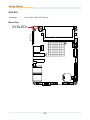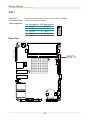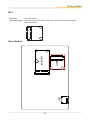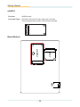
1
EmCORE-i2305
3.5” Compact Board
User’s Manual
Version 1.0
2014.07
1
This page is intentionally left blank.
-2-
Revision History
Version
Release Time
1.0
July 2014
-i-
Description
Initial release
This page is intentionally left blank.
- ii -
Contents
Table of Contents
Revision History..................................................................................i
Table of Contents..............................................................................iii
Preface................................................................................................v
Copyright Notice...................................................................................... v
Declaration of Conformity........................................................................ v
CE..................................................................................................... v
FCC Class A.................................................................................... vi
RoHS............................................................................................... vi
SVHC / REACH...............................................................................vii
Warning...................................................................................................vii
Replacing Lithium Battery.......................................................................vii
Technical Support...................................................................................vii
Warranty................................................................................................viii
Chapter 1 - Introduction.....................................................................1
1.1. The Product...................................................................................... 2
1.2. About this Manual............................................................................. 2
1.3. Specifications.................................................................................... 3
1.4. Inside the Package........................................................................... 4
1.5. Ordering Information......................................................................... 4
Chapter 2 - Getting Started................................................................5
2.1. Board Dimensions ............................................................................ 6
2.1.1. SKU-E3825............................................................................. 6
2.1.2. SKU-E3845............................................................................. 7
2.2. Block Diagram................................................................................... 8
2.3. Jumpers & Connectors..................................................................... 9
2.3.1. Layout..................................................................................... 9
2.3.2. Jumpers................................................................................ 11
2.3.3. Connectors........................................................................... 16
2.4. Driver Installation Notes.................................................................. 40
Chapter 3 - BIOS...............................................................................41
3.1. Main................................................................................................ 43
3.2. Advanced........................................................................................ 44
3.2.1. Boot Configuration................................................................ 45
3.2.2. PCI Express Configuration................................................... 45
3.2.3. USB Configuration................................................................ 45
3.2.4. LPSS & SCC Configuration.................................................. 46
3.2.5. Video Configuration.............................................................. 46
3.2.6. SATA Configuration............................................................... 47
3.2.7 ACPI Table/Feature Control................................................... 47
- iii -
Contents
3.2.8. SIO FINTEK71869E............................................................. 48
3.3. Security........................................................................................... 49
3.4. Power.............................................................................................. 50
3.4.1 Advanced CPU Control.......................................................... 51
3.5. Boot................................................................................................. 53
3.6. Exit.................................................................................................. 55
Appendices.......................................................................................57
Appendix A. Watchdog Timer (WDT) Setting......................................... 58
Appendix B. Digital I/O Setting............................................................... 59
- iv -
Preface
Preface
Copyright Notice
All Rights Reserved.
The information in this document is subject to change without prior notice in
order to improve the reliability, design and function. It does not represent a
commitment on the part of the manufacturer.
Under no circumstances will the manufacturer be liable for any direct, indirect,
special, incidental, or consequential damages arising from the use or inability
to use the product or documentation, even if advised of the possibility of such
damages.
This document contains proprietary information protected by copyright. All rights
are reserved. No part of this manual may be reproduced by any mechanical,
electronic, or other means in any form without prior written permission of the
manufacturer.
Declaration of Conformity
CE
The CE symbol on your product indicates that it is in compliance with the
directives of the Union European (EU). A Certificate of Compliance is available
by contacting Technical Support.
This product has passed the CE test for environmental specifications when
shielded cables are used for external wiring. We recommend the use of shielded
cables. This kind of cable is available from ARBOR. Please contact your local
supplier for ordering information.
This product has passed the CE test for environmental specifications. Test
conditions for passing included the equipment being operated within an
industrial enclosure. In order to protect the product from being damaged by ESD
(Electrostatic Discharge) and EMI leakage, we strongly recommend the use of
CE-compliant industrial enclosure products.
Warning
This is a class A product. In a domestic environment this product may cause
radio interference in which case the user may be required to take adequate
measures.
-v-
Preface
FCC Class A
This device complies with Part 15 of the FCC Rules. Operation is subject to the
following two conditions:
(1) This device may not cause harmful interference, and
(2) This device must accept any interference received, including interference that may cause undesired operation.
NOTE:
This equipment has been tested and found to comply with the limits for a
Class A digital device, pursuant to Part 15 of the FCC Rules. These limits are
designed to provide reasonable protection against harmful interference when the
equipment is operated in a commercial environment. This equipment generates,
uses, and can radiate radio frequency energy and, if not installed and used in
accordance with the instruction manual, may cause harmful interference to radio
communications. Operation of this equipment in a residential area is likely to
cause harmful interference in which case the user will be required to correct the
interference at his own expense.
RoHS
ARBOR Technology Corp. certifies that all components in its products are
in compliance and conform to the European Union’s Restriction of Use of
Hazardous Substances in Electrical and Electronic Equipment (RoHS) Directive
2002/95/EC.
The above mentioned directive was published on 2/13/2003. The main purpose
of the directive is to prohibit the use of lead, mercury, cadmium, hexavalent
chromium, polybrominated biphenyls (PBB), and polybrominated diphenyl
ethers (PBDE) in electrical and electronic products. Member states of the EU
are to enforce by 7/1/2006.
ARBOR Technology Corp. hereby states that the listed products do not contain
unintentional additions of lead, mercury, hex chrome, PBB or PBDB that exceed
a maximum concentration value of 0.1% by weight or for cadmium exceed
0.01% by weight, per homogenous material. Homogenous material is defined as
a substance or mixture of substances with uniform composition (such as solders,
resins, plating, etc.). Lead-free solder is used for all terminations (Sn(96-96.5%),
Ag(3.0-3.5%) and Cu(0.5%)).
- vi -
Preface
SVHC / REACH
To minimize the environmental impact and take more responsibility to the earth
we live, Arbor hereby confirms all products comply with the restriction of SVHC
(Substances of Very High Concern) in (EC) 1907/2006 (REACH --Registration,
Evaluation, Authorization, and Restriction of Chemicals) regulated by the
European Union.
All substances listed in SVHC < 0.1 % by weight (1000 ppm)
Warning
Single Board Computers and their components contain very delicate
Integrated Circuits (IC). To protect the Single Board Computer and its
components against damage from static electricity, you should always follow the
following precautions when handling it :
1. Disconnect your Single Board Computer from the power source when you
want to work on the inside.
2. Hold the board by the edges and try not to touch the IC chips, leads or
circuitry.
3. Use a grounded wrist strap when handling computer components.
4. Place components on a grounded antistatic pad or on the bag that comes
with the Single Board Computer, whenever components are separated from
the system.
Replacing Lithium Battery
Incorrect replacement of the lithium battery may lead to a risk of explosion.
The lithium battery must be replaced with an identical battery or a battery type
recommended by the manufacturer.
Do not throw lithium batteries into the trash-can. It must be disposed of in
accordance with local regulations concerning special waste.
Technical Support
If you have any technical difficulties, please do not hesitate to call or e-mail our
customer service.
http://www.arbor.com.tw
E-mail:[email protected]
- vii -
Preface
Warranty
This product is warranted to be in good working order for a period of two years
from the date of purchase. Should this product fail to be in good working order
at any time during this period, we will, at our option, replace or repair it at no
additional charge except as set forth in the following terms. This warranty does
not apply to products damaged by misuse, modifications, accident or disaster.
Vendor assumes no liability for any damages, lost profits, lost savings or any
other incidental or consequential damage resulting from the use, misuse of, or
inability to use this product. Vendor will not be liable for any claim made by any
other related party.
Vendors disclaim all other warranties, either expressed or implied, including but
not limited to implied warranties of merchantability and fitness for a
particular purpose, with respect to the hardware, the accompanying product’s
manual(s) and written materials, and any accompanying hardware. This limited
warranty gives you specific legal rights.
Return authorization must be obtained from the vendor before returned
merchandise will be accepted. Authorization can be obtained by calling or
faxing the vendor and requesting a Return Merchandise Authorization (RMA)
number. Returned goods should always be accompanied by a clear problem
description.
- viii -
1
Chapter 1
Introduction
Chapter 1 - Introduction
-1-
Introduction
1.1. The Product
•
•
•
•
•
•
•
Support Intel® Atom™ Processor E3800 family
Integrated Gigabit Ethernet
LVDS, Analog RGB Port, HDMI port
Support Dual Independent Displays
Soldered Onboard 16GB eMMC (optional)
Extended Operating Temp.: -20 ~ 70°C
Wide Range Operating Temp.: -40 ~ 85°C
(WT series)
1.2. About this Manual
This manual is intended for experienced users and integrators with hardware
knowledge of computers. If you are not sure about the description in this manual,
consult your vendor before further handling.
We recommend that you keep one copy of this manual for the quick reference
for any necessary maintenance in the future. Thank you for choosing ARBOR
products.
-2-
Introduction
1.3. Specifications
Form Factor
3.5" Compact Board
CPU
Soldered onboard Intel® Atom™ Processor E3825 dual-core 1.33GHz
or E3845 quad-core 1.91GHz
System Memory
1 x DDR3L SO-DIMM socket, supporting SDRAM up to 8GB
Graphics Chipset
Integrated Intel® HD Graphics
Graphics Interface
HDMI
Vertical HDMI connector
LCD
Dual-channel 24-bit LVDS
Analog RGB that supports resolution up to 2048 x 1536
Ethernet
2 x Realtek® RTL8111 PCIe GbE controllers
BIOS
Insyde BIOS
Audio
Realtek ALC662 HD Audio CODEC, MIC-in/ Line-out/Line-in
1 x Serial ATA port with 300MB/s HDD transfer rate
Storage
1 x mSATA socket
Soldered onboard 16GB eMMC(optional)
Serial Port
Universal Serial Bus
Digital I/O
2 x COM ports (1 x RS-232 port, 1 x RS-232/485 port selectable)
4 x USB 2.0 ports
1 x USB 3.0 port
8-bit programmable Digital Input/Ouput
1 x Mini-card socket
Expansion Bus
1 x Micro-SDXC socket
2 x I2C ports(optional)
Power Requirement
+12V DC
Power Consumption
0.56A@+12V (typical) (E3825)
0.65A@+12V (typical) (E3845)
Operating Temp.
-20°C ~ 70°C (-4°F ~ 158°F)
-40°C ~ 85ºC (-40°F ~ 185ºF, WT series)
Operating Humidity
10% ~ 95% @ 70°C (non-condensing)
10% ~ 95% @ 85ºC (non-condensing, WT series)
Watchdog Timer
1~255 levels reset
Dimension (L x W)
146 x 102 mm (5.7” x 4.0”)
-3-
Introduction
1.4. Inside the Package
Before starting to install the single board, make sure the following items are
shipped:
1 x EmCORE-i2305 3.5" Compact Board with heatsink
1 x Driver CD
1 x Quick Installation Guide
If any of the aforelisted items is damaged or missing, contact your vendor
immediately.
1.5. Ordering Information
EmCORE-i2305-E3825
Intel® Atom™ Processor E3825 3.5” Compact Board
EmCORE-i2305-WT-E3825
Wide range temperature Intel® Atom™ Processor E3825 3.5”
Compact Board
EmCORE-i2305-E3845
Intel® Atom™ Processor E3845 3.5” Compact Board
EmCORE-i2305-WT-E3845
Wide range temperature Intel® Atom™ Processor E3845 3.5”
Compact Board
FCDB-1293
4 x COM ports, 8-bit digital I/O daughterboard
CBK-07-2305-00
Cable kit
1 x AUDIO cable
2 x COM port latching cables
1 x Keyboard & mouse latching y-cable
1 x SATA cable
1 x SATA power cable
1 x USB cable
-4-
2
Chapter 2
Getting
Started
Chapter 2 - Getting Started
-5-
Getting Started
2.1. Board Dimensions
2.1.1. SKU-E3825
101.96
98.58
3.38
8.84
8.84
98.58
CS
4P
.2X
Ø3
(32)
3.38
146
142.77
142.77
1.6
Unit: mm
-6-
Getting Started
2.1.2. SKU-E3845
101.96
98.58
3.38
8.84
8.84
3.38
4P
.2X
Ø3
98.58
146
142.77
142.77
CS
(25.5)
1.6
Unit: mm
-7-
Getting Started
2.2. Block Diagram
PWR1
+12 DC-in
USB3
Type A conn.
DDR3L-1333MHz (up to 8GB)
1 x USB 3.0/2.0 port
1 x DDR3L
SO-DIMM socket
VGA1
DB15 female
Analog RGB
USB1
2x5-pin 2.00mm pitch
latching box header
MC1
Half-size
Mini-Card socket
USB2
Type A conn.
SDXC1
Micro-SDXC card socket
SATA1
SATA connector
mSATA1
Full-size
Mini-Card socket
2 x USB 2.0 ports
USB Hub
GL852G
USB 2.0
1 x eDP port
NXP
PTN3460
Dual Channels 24-bit LVDS
1 x USB 2.0 port
1 x DP port
1 x PCIe x 1
2 x USB 2.0 ports
1 x SD 3.0
Intel®
Atom
E3825 DC
1.33GHz/
E3845 QC
1.91GHz
Processor
SATA0
HDMI1
Vertical HDMI conn.
1 x PCIe x 1 Realtek RTL8111
LAN controller
GbE
LAN1
RJ-45 connector
1 x PCIe x 1 Realtek RTL8111
LAN controller
GbE
LAN2
RJ-45 connector
HD Link
HD CODEC
ALC662
Mic-in/Line-in/Line-out
COM1 (RS-232)
SATA1
COM2 (RS-232/485 selectable)
I2C
1x5-pin x2, 2.00mm pitch
latching box header
Onboard eMMC
up to 16GB
LVDS1
F-13-30DP-1.25V
LPC IF
2 x I2C(optional)
eMMC 4.5(optional)
Super IO
Fintek
71869ED
KB, MS
8-bit Digital I/O
-8-
AUDIO1
2x5-pin 2.00mm pitch
latching box header
COM1
2x5-pin 2.00mm pitch
latching box header
COM2
2x5-pin 2.00mm pitch
latching box header
KBMS1
ACES, 88462-06
DIO1
2x5-pin 2.00mm pitch
latching box header
Getting Started
2.3. Jumpers & Connectors
The board comes with some connectors to join some devices and also some
jumpers to alter the hardware configuration. The following in this chapter will
explicate each of these components one-by-one.
2.3.1. Layout
This section will provide an overview of this board, both the top and bottom sides.
Board Top
2
6
1
5
72 74
2
204
9
10
203
71 73
1
1
1
2
1
10
9
1
1
4
29
30
1
2
2
1
3
1
1
10
9
4
2
2
1
9
10
2
CO
M
PO
NE
NT
1
1
NO COMPONENT
NO COMPONENT
NO
4
1
NO
NT
NE
PO
M
CO
1
9
10
1
1
10
10
2
-9-
2
2
1
1
10
9
6
5
7
4
3
2
1
1
4
1
9
Getting Started
Board Bottom
1
15
16
18
MC1
mSATA1
52
18
16
2
51
17
15
1
1 2 3 4 56
7 8
SD1
- 10 -
2
52
17
51
Getting Started
2.3.2. Jumpers
JPIC1
Function:
Sets the AT/ATX mode
Jumper Type:
2.00mm pitch 2x3-pin header
Setting:
Pin Description
2-4
AT
4-6
ATX mode (default)
2
6
1
5
2
6
1
5
Note to make consistent setting in BIOS | Advanced menu | ACPI Settings |
Power-Supply Type to avoid possible conflict. See 3.2.1. Boot Configuration
on page 45.
Board Top
2
6
1
5
JPIC1
72 74
2
204
9
10
203
71 73
1
1
1
2
1
10
9
1
1
4
29
30
1
2
2
1
3
1
1
10
9
4
2
2
1
9
10
2
CO
M
PO
NEN
T
1
1
NO COMPONENT
NO COMPONENT
NO
4
1
NO
T
NEN
PO
M
CO
1
9
10
10
2
- 11 -
10
1
1
2
2
1
1
10
9
6
5
7
4
3
2
1
1
1
4
9
Getting Started
JINV1
Function:
Sets the LCD inverter voltage
Jumper Type:
2.54mm pitch 1x3-pin header
Setting:
Pin Description
1-2 +12V
2-3 +5V (default)
3
2
1
3
2
1
Board Top
2
6
1
5
72 74
2
204
9
10
203
71 73
1
1
1
2
1
JINV1
9
10
1
1
4
29
30
1
2
2
1
3
1
1
10
9
4
2
2
1
9
10
2
CO
M
PO
NEN
T
1
1
NO COMPONENT
NO COMPONENT
NO
4
1
NO
M
CO
1
PO
T
NEN
9
10
10
2
- 12 -
10
1
1
2
2
1
1
10
9
6
5
7
4
3
2
1
1
4
1
9
Getting Started
JVLCD1
Function:
Sets the power voltage fro LVDS1 LCD
Jumper Type:
2.54mm pitch 1x3-pin header
Setting:
Pin Description
1-2
+5V
2-3
+3.3V (default)
3
2
1
3
2
1
Board Top
2
6
1
5
72 74
2
204
9
10
203
71 73
1
1
1
2
JVLCD1
1
10
9
1
1
4
29
30
1
2
2
1
3
1
1
10
9
4
2
2
1
9
10
2
CO
M
PO
NEN
T
1
1
NO COMPONENT
NO COMPONENT
NO
4
1
NO
CO
PO
M
1
T
NEN
9
10
10
2
- 13 -
10
1
1
2
2
1
1
10
9
6
5
7
4
3
2
1
1
4
1
9
Getting Started
JBAT1
Function:
Clears/keeps CMOS
Jumper Type:
2.00 mm pitch 1x3-pin header
Setting:
Pin Description
1-2
Keeps CMOS (default)
2-3
Clears CMOS
3
2
1
3
2
1
Board Top
2
6
1
5
72 74
2
204
9
10
203
71 73
1
1
1
2
1
10
9
1
1
4
29
30
1
2
2
1
3
1
1
10
9
4
2
2
1
9
10
2
CO
M
PO
NEN
T
1
1
NO COMPONENT
NO COMPONENT
NO
4
1
NO
M
CO
1
PO
T
NEN
9
10
10
2
- 14 -
10
1
1
2
2
1
1
10
9
6
5
7
4
3
2
1
1
4
1
9
JBAT1
Getting Started
JRS1
Function:
COM2 RS-232/485 selection
Jumper Type:
2.00 mm pitch 1x3-pin header
Setting:
Pin Description
1-2
RS-232 (default)
2-3
RS-485
3
2
1
3
2
1
Note: To enable RS-485 Port (CN1) , beside jumper setting, please go to
BIOS Setting Menu to Enable RS-485 mode of COM2. Option is under
Advanced/ SIO FINTEK71869E/ RS-232/485 Setting/ RS-485. After
enabled RS-485 Mode, CN1 will be activated as RS-485 port
Board Top
2
6
1
5
72 74
2
204
9
10
203
71 73
1
1
1
2
1
9
10
1
1
4
29
30
1
2
2
1
3
1
1
10
9
4
2
2
1
9
10
2
CO
M
PO
NEN
T
1
1
NO COMPONENT
NO COMPONENT
NO
4
1
NO
T
NEN
PO
M
CO
1
9
10
10
2
- 15 -
10
1
1
2
2
1
1
10
9
6
5
7
4
3
2
1
1
4
1
9
JRS1
Getting Started
2.3.3. Connectors
INV1
Function:
LCD inverter connector
Connector Type:
2.00mm pitch 1x5-pin box wafer
Pin Assignment:
Pin Description
1
Vin
2
GND
3
on/off
4
Brightness control
5
GND
1
5
Board Top
2
6
1
5
72 74
2
204
9
10
203
71 73
1
1
1
2
INV1
1
10
9
1
1
4
29
30
1
2
2
1
3
1
1
10
9
4
2
2
1
9
10
2
CO
M
PO
NEN
T
1
1
NO COMPONENT
NO COMPONENT
NO
4
1
NO
T
NEN
PO
M
CO
1
9
10
10
2
- 16 -
10
1
1
2
2
1
1
10
9
6
5
7
4
3
2
1
1
4
1
9
Getting Started
LVDS1
Function:
LVDS LCD panel connector
Connector Type:
ACES 1.25mm 87209-3040-06 connector that supports 24-bit dual channels.
Pin Assignment:
Pin
2
4
6
8
10
12
14
16
18
20
Description
VDD
TX2_CLK+
TX2_CLKGND
TX2_D0+
TX2_D0GND
TX2_D1+
TX2_D1GND
Pin
22
24
26
28
30
1
3
5
7
9
Description
TX2_D2+
TX2_D2GND
TX2_D3+
TX2_D3VDD
TX1_CLK+
TX1_CLKGND
TX1_D0+
Pin
11
13
15
17
19
21
23
25
27
29
Description
TX1_D0GND
TX1_D1+
TX1_D1GND
TX1_D2+
TX1_D2GND
TX1_D3+
TX1_D3-
2
1
30
29
Board Top
2
6
1
5
72 74
2
204
9
10
203
71 73
1
1
1
2
1
10
9
1
1
4
29
30
1
2
LVDS1
2
1
Pin1
Pin2
3
1
1
10
9
4
2
2
1
9
10
2
CO
M
PO
NEN
T
1
1
NO COMPONENT
NO COMPONENT
NO
4
1
NO
CO
T
NEN
PO
M
1
9
10
10
2
- 17 -
10
1
1
2
2
1
1
10
9
6
5
7
4
3
2
1
1
4
1
9
Getting Started
KBMS1
Function:
Keyboard & Mouse connector
Connector Type:
2.0mm pitch 1x6-pin header
Pin Assignment:
Pin
Description
1
KB_DATA
2
GND
3
MS_DATA
4
KB_CLK
5
PS2_VCC
6
MS_CLK
1
Board Top
2
6
1
5
72 74
2
204
9
10
203
71 73
1
1
1
2
1
9
10
1
1
4
29
30
1
2
2
1
3
KBMS1
1
1
10
9
4
2
2
1
9
10
2
CO
M
PO
NEN
T
1
1
NO COMPONENT
NO COMPONENT
NO
4
1
NO
M
CO
1
T
NEN
PO
9
10
10
2
- 18 -
10
1
1
2
2
1
1
10
9
6
5
7
4
3
2
1
1
4
1
9
Getting Started
COM1&2
Function:
Serial port connector
Connector Type:
2.00mm pitch 2x5-pin wafer connector
Pin Assignment:
Pin
2
4
6
8
10
Description
RX
DTR#
DSR#
CTS#
N/C
Pin
1
3
5
7
9
Description
DCD#
TXD
GND
RTS#
RI#
2
10
1
9
Board Top
2
6
1
5
72 74
2
204
9
10
203
71 73
1
1
1
2
1
10
9
1
1
4
29
30
1
2
2
1
3
1
1
10
9
4
2
2
1
9
10
2
CO
M
PO
NEN
T
1
1
NO COMPONENT
NO COMPONENT
NO
4
1
NO
M
CO
1
PO
T
NEN
9
10
10
2
- 19 -
10
1
1
2
2
1
1
10
9
6
5
7
4
3
2
1
1
4
1
9
COM1&2
Getting Started
FAN1
Function:
Fan connector
Connector Type:
2.54mm pitch 1x4-pin wafer connector.
Pin Assignment:
Pin Description
1
GND
2
+12V
3
Fan_Detect
4
Control
1
2
3
4
Board Top
2
6
1
5
72 74
2
204
9
10
203
71 73
1
1
1
2
1
9
10
1
1
4
29
30
1
2
2
1
3
1
1
10
9
4
2
2
1
9
10
2
CO
M
PO
NEN
T
1
1
NO COMPONENT
NO COMPONENT
NO
4
1
NO
CO
T
NEN
PO
M
1
9
10
10
2
- 20 -
10
1
1
2
2
1
1
10
9
6
5
7
4
3
2
1
1
4
1
9
FAN1
Getting Started
CN1
Function:
RS-485 connector
Connector Type:
2.00mm pitch 1x2-pin Box Wafer Connector
Pin Assignment:
Pin Description
1 DATA2 DATA+
1
Note: To enable this port, please refer to JRS1 on page 15 .
Board Top
2
6
1
5
72 74
2
204
9
10
203
71 73
1
1
1
2
1
9
10
1
1
4
29
30
1
2
2
1
3
1
1
10
9
4
2
2
1
9
10
2
CO
M
PO
NEN
T
1
1
NO COMPONENT
NO COMPONENT
NO
4
1
NO
CO
T
NEN
PO
M
1
9
10
10
2
- 21 -
10
1
1
2
2
1
1
10
9
6
5
7
4
3
2
1
1
4
1
9
CN1
Getting Started
DIO1
Function:
Digital I/O connector
Connector Type:
2.00mm pitch 2x5-pin wafer connector
Pin Assignment:
Pin
2
4
6
8
10
Description Pin Description
GPIO1
1 GPIO0
GPIO3
3 GPIO2
GPIO5
5 GPIO4
GPIO7
7 GPIO6
GND
9 +5V
2
1
10
9
Board Top
2
6
1
5
72 74
2
204
9
10
203
71 73
1
1
1
2
1
9
10
1
1
4
29
30
1
2
2
1
3
1
1
10
9
4
2
2
1
9
10
2
CO
M
PO
NEN
T
1
1
NO COMPONENT
NO COMPONENT
NO
4
1
NO
M
CO
1
PO
T
NEN
9
10
10
2
- 22 -
10
1
1
2
2
1
1
10
9
6
5
7
4
3
2
1
1
4
1
9
DIO1
Getting Started
I2C1
Function:
I2C connector
Connector Type:
2.00mm pitch 2x5-pin wafer connector
Pin Assignment:
Pin
2
4
6
8
10
Description
+3.3V
I2C_CLK1(3.3V)
I2C_DATA1(3.3V)
GND
GND
Pin
1
3
5
7
9
Description
+3.3V
I2C_CLK0(3.3V)
I2C_DATA0(3.3V)
GND
GND
Board Top
2
6
1
5
72 74
2
204
9
10
203
71 73
1
1
1
2
1
10
9
1
1
4
29
30
1
2
2
1
3
1
1
10
9
4
2
2
1
9
10
2
CO
M
PO
NEN
T
1
1
NO COMPONENT
NO COMPONENT
NO
4
1
NO
M
CO
1
PO
T
NEN
9
10
1
1
2
2
1
1
10
9
6
5
7
4
3
2
1
1
4
1
9
10
2
10
I2C1
- 23 -
2
1
10
9
Getting Started
AUDIO1
Function:
Audio connector
Connector Type:
2.00mm pitch 2x5-pin header
Pin Assignment:
Pin
1
3
5
7
9
Description
Line Left In
GND
MIC1
GND
Line-out Left
Pin
2
4
6
8
10
Description
Line Right In
GND
MIC2
GND
Line-out Right
1
2
9
10
Board Top
2
6
1
5
72 74
2
204
9
10
203
71 73
1
1
1
2
1
10
9
1
1
4
29
30
1
2
2
1
3
1
1
10
9
4
2
2
1
9
10
2
CO
M
PO
NEN
T
1
1
NO COMPONENT
NO COMPONENT
NO
4
1
NO
M
CO
1
PO
T
NEN
9
10
1
1
- 24 -
10
10
2
AUDIO1
2
2
1
1
10
9
6
5
7
4
3
2
1
1
4
1
9
Getting Started
SATA1
Function:
Serial ATA connector
Pin Assignment:
The pin assignments conform to the industry standard.
Board Top
2
6
1
5
72 74
2
204
9
10
203
71 73
1
1
1
2
1
10
9
1
1
4
29
30
1
2
2
1
3
1
1
10
9
4
2
2
1
9
10
2
CO
M
PO
NEN
T
1
1
NO COMPONENT
NO COMPONENT
NO
4
1
NO
M
CO
1
PO
T
NEN
9
10
1
1
- 25 -
10
10
2
SATA1
2
2
1
1
10
9
6
5
7
4
3
2
1
1
4
1
9
Getting Started
PWROUT1
Function:
SATA power connector
Connector Type:
2.54mm pitch 1x4-pin wafer connector
Pin Assignment:
Pin Description
1
VCC 5V
2
GND
3
GND
4
VCC 12V
1
Board Top
2
6
1
5
72 74
2
204
9
10
203
71 73
1
1
1
2
1
10
9
1
1
4
29
30
1
2
2
1
3
1
1
10
9
4
2
2
1
9
10
2
CO
M
PO
NEN
T
1
1
NO COMPONENT
NO COMPONENT
NO
4
1
NO
M
CO
1
T
NEN
PO
9
10
1
1
- 26 -
10
10
2
PWROUT1
2
2
1
1
10
9
6
5
7
4
3
2
1
1
4
1
9
Getting Started
LAN1, 2
Function:
Ethernet connectors
Connector Type:
RJ-45 connector that supports 10/100/1000Mbps fast Ethernet
Pin Assignment:
Pin
1
3
5
7
Description
MDI0+
MDI1+
MDI2+
MDI3+
Pin
2
4
6
8
Description
MDI0MDI1MDI2MDI3-
1
8
Board Top
2
6
1
5
72 74
2
204
9
10
203
71 73
1
1
1
2
1
10
9
1
1
4
29
30
1
2
2
1
3
1
1
10
9
4
2
2
1
9
LAN2
10
2
CO
M
PO
NEN
T
1
1
NO COMPONENT
1
NO
M
CO
1
NO COMPONENT
NO
4
LAN1
T
NEN
PO
9
10
1
1
10
10
2
- 27 -
2
2
1
1
10
9
6
5
7
4
3
2
1
1
1
4
9
Getting Started
RES1
Function:
Reset button
Board Top
2
6
1
5
72 74
2
204
9
10
203
71 73
1
1
1
2
1
9
10
1
1
4
29
30
1
2
2
1
3
1
1
10
9
4
2
2
1
9
10
2
CO
M
PO
NEN
T
1
1
1
NO
M
CO
1
NO COMPONENT
NO
4
NO COMPONENT
RES1
T
NEN
PO
9
10
1
1
10
10
2
- 28 -
2
2
1
1
10
9
6
5
7
4
3
2
1
1
4
1
9
Getting Started
HDMI1
Function:
HDMI connector
Connector Type:
19-pin HDMI connector with flange
Pin Assignment:
The pin assignments conform to the industry standard.
1
19
18
2
Board Top
2
6
1
5
72 74
2
204
9
10
203
71 73
1
1
1
2
1
9
10
1
1
4
29
30
1
2
2
1
3
HDMI1
1
1
10
9
4
2
2
1
9
10
2
CO
M
PO
NEN
T
1
1
NO COMPONENT
NO COMPONENT
NO
4
1
NO
M
CO
1
PO
T
NEN
9
10
1
1
10
10
2
- 29 -
2
2
1
1
10
9
6
5
7
4
3
2
1
1
4
1
9
Getting Started
USB2
Function:
USB 3.0 connector
Connector Type:
USB 3.0/2.0 type-A connectors
Pin Assignment:
The pin assignments conform to the industry
standard.
Board Top
2
6
1
5
72 74
2
204
9
10
203
71 73
1
1
1
2
1
10
9
1
1
4
29
30
1
2
2
USB2
1
3
1
1
10
9
4
2
2
1
9
10
2
CO
M
PO
NEN
T
1
1
NO COMPONENT
NO COMPONENT
NO
4
1
NO
M
CO
1
T
NEN
PO
9
10
1
1
10
10
2
- 30 -
2
2
1
1
10
9
6
5
7
4
3
2
1
1
1
4
9
Getting Started
USB3
Function:
Double-stacked USB connectors
Connector Type:
Two USB 2.0/1.0 type-A connectors
Pin Assignment:
The pin assignments conform to the industry
standard.
Board Top
2
6
1
5
72 74
2
204
9
10
203
71 73
1
1
1
2
1
10
9
1
29
USB3
1
4
30
1
2
2
1
3
1
1
10
9
4
2
2
1
9
10
2
CO
M
PO
NEN
T
1
1
NO COMPONENT
NO COMPONENT
NO
4
1
NO
M
CO
1
T
NEN
PO
9
10
1
1
10
10
2
- 31 -
2
2
1
1
10
9
6
5
7
4
3
2
1
1
4
1
9
Getting Started
USB1
Function:
USB 2.0 connector
Connector Type:
2.00mm pitch 2x5-pin wafer connector
Pin Assignment:
Pin
2
4
6
8
10
Description
+5VUSBP1USBP1+
GND
GND
Pin
1
3
5
7
9
Description
+5V
USBP0USBP0+
GND
GND
2
1
10
9
Board Top
2
6
1
5
72 74
2
204
9
10
203
71 73
1
USB1
1
1
2
1
10
9
1
1
4
29
30
1
2
2
1
3
1
1
10
9
4
2
2
1
9
10
2
CO
M
PO
NEN
T
1
1
NO COMPONENT
NO COMPONENT
NO
4
1
NO
CO
T
NEN
PO
M
1
9
10
1
1
10
10
2
- 32 -
2
2
1
1
10
9
6
5
7
4
3
2
1
1
4
1
9
Getting Started
VGA1
Function:
Analog RGB connector
Connector Type:
D-Sub 15-pin female connector
Pin Assignment:
Pin
1
2
3
4
5
6
7
8
Description.
Pin
Description
RED
GREEN
BLUE
N/C
GND
GND
GND
GND
9
10
11
12
13
14
15
5V
GND
N/C
D-DATA
H-SYNC
V-SYNC
D-DCLK
1
11
5
15
Board Top
VGA1
2
6
1
5
72 74
2
204
9
10
203
71 73
1
1
1
2
1
10
9
1
1
4
29
30
1
2
2
1
3
1
1
10
9
4
2
2
1
9
10
2
CO
M
PO
NEN
T
1
1
NO COMPONENT
NO COMPONENT
NO
4
1
NO
M
CO
1
T
NEN
PO
9
10
1
1
10
10
2
- 33 -
2
2
1
1
10
9
6
5
7
4
3
2
1
1
4
1
9
Getting Started
SYSLED1:
Function:
Power ON & HDD LED Indicator
Board Top
SYSLED1
2
6
1
5
72 74
2
204
9
10
203
71 73
1
1
1
2
1
10
9
1
1
4
29
30
1
2
2
1
3
1
1
10
9
4
2
2
1
9
10
2
CO
M
PO
NEN
T
1
1
NO COMPONENT
NO COMPONENT
NO
4
1
NO
M
CO
1
PO
T
NEN
9
10
1
1
10
10
2
- 34 -
2
2
1
1
10
9
6
5
7
4
3
2
1
1
4
1
9
Getting Started
12VIN1
Function:
Supplies ATX +12V
Connector Type:
4-pin power connector
Pin Assignment:
Pin Description
2 GND
1 GND
Pin Description
4 +12V
3 +12V
2
4
1
3
Board Top
12VIN1
2
6
1
5
72 74
2
204
9
10
203
71 73
1
1
1
2
1
9
10
1
1
4
29
30
1
2
2
1
3
1
1
10
9
4
2
2
1
9
10
2
CO
M
PO
NEN
T
1
1
NO COMPONENT
NO COMPONENT
NO
4
1
NO
M
CO
1
T
NEN
PO
9
10
1
1
10
10
2
- 35 -
2
2
1
1
10
9
6
5
7
4
3
2
1
1
4
1
9
Getting Started
JFRT1
Function:
Provides connectors to front-panel status LED and toggles
Connector Type:
2.54mm pitch 2x5-pin header
Pin Assignment:
Pin
1
3
5
7
9
Description Pin Description
RESET+
2 RESETPLED+
4 PLEDHLED+
6 HLEDSPEAK+
8 SPEAKPSON+
10 PSON-
1
2
9
10
Board Top
2
6
1
5
72 74
2
204
9
10
JFRT1
203
71 73
1
1
1
2
1
10
9
1
1
4
29
30
1
2
2
1
3
1
1
10
9
4
2
2
1
9
10
2
CO
M
PO
NEN
T
1
1
NO COMPONENT
NO COMPONENT
NO
4
1
NO
M
CO
1
PO
T
NEN
9
10
10
2
- 36 -
10
1
1
2
2
1
1
10
9
6
5
7
4
3
2
1
1
4
1
9
Getting Started
MC1
Function:
Mini-card socket
Connector Type:
Onboard 0.8mm-pitch 52-pin edge card connector interconnected with SIM card socket.
2
1
15
17
16
18
51 52
Board Bottom
1
15
16
18
mSATA1
52
17
51
2
MC1
52
18
16
2
51
17
15
1
1 2 3 4 56
7 8
SD1
- 37 -
Getting Started
mSATA1
Function:
mSATA socket
Connector Type:
Onboard 0.8mm pitch 52-pin edge card connector
The pin assignments conform to the industry standard.
2
1
15
17
16
18
51 52
Board Bottom
1
15
16
18
mSATA1
52
17
51
2
MC1
52
18
2
16
51
17
15
1
1 2 3 4 56
7 8
SD1
- 38 -
Getting Started
SD1
Function:
microSD card socket
The pin assignments conform to the industry
standard.
1 2 3 4 56
Board Bottom
1
15
16
18
mSATA1
52
17
51
2
MC1
52
18
16
2
51
17
15
1
1 2 3 4 56
7 8
SD1
- 39 -
7 8
2.4. Driver Installation Notes
The board supports Windows 7 and Windows 8.1. Find the necessary drivers
on the CD that comes with your purchase. For different OS, the driver/utility
installation may vary slightly, but generally they are similar. DO follow the
sequence below to install all drivers to prevent errors:
Chipset→.NET Framework→Graphics→Audio→LAN→USB3.0
Find the drivers on CD by the following paths:
Windows 7
Device
Audio
Driver Path
\Audio\32bit_Win7_Win8_Win81_R275
\Audio\64bit_Win7_Win8_Win81_R275
Chipset
\Chipset\SetupChipset_10.0.13_PC
Ethernet
\Ethernet\Realtek\Win7\Install_Win7_7085_05222014
GPIO
\GPIO\windows 7 32_64\Intel Atom E3800 Win7 IO Drivers_Gold_v1.0 package 501232_
20140211
Graphic
\Graphics\WIN7_32\Intel_EMGD.WIN7_PC_Version_36_15_0_1073
\Graphics\WIN7_64\Intel_EMGD.WIN7_PC_Version_37_15_0_1073
TXE
\TXE\Installers (Only for 64-bit)
USB3.0
\USB3.0\Intel(R) USB 3.0 eXtensible Host Controller_Win7_32bit_64bit_R3.0.0.33
Serial IO
\Serial IO\Intel Processor IO Drivers_Win7_32bit_64bit_Gold_v2.0
Windows 8.1
Device
Audio
Driver Path
\Audio\32bit_Win7_Win8_Win81_R275
\Audio\64bit_Win7_Win8_Win81_R275
Chipset
\Chipset\SetupChipset_10.0.13_PC
Ethernet
\Ethernet\Realtek\Win8_8.1\Install_Win8_8.1_8031_05222014
GPIO
\GPIO\Kit 100882 20140211 windows 8.1 64\GPIO(Only for 64-bit)
Graphic
\Graphics\WIN8_32\15.33.22.3621
\Graphics\WIN8_64\15.33.22.64.3621
TXE
\TXE\Installers
Serial IO
\Serial IO\SerialIO_Installer_Win8.1_64bit_WW23
- 40 -
3
Chapter 3
BIOS
Chapter 3 - BIOS
- 41 -
BIOS
The BIOS Setup utility is featured by AMI BIOS to configure the system settings
stored in the system’s BIOS ROM. AMI BIOS is activated once the computer
powers on.
After entering the utility, use the left/right arrow keys to navigate between the top
menus and use the down arrow key to access one.
Menu
Main
Advanced
Security
Power
Boot
Exit
Description
See 3.1. Main on page 43.
See 3.2. Advanced on page 44.
See 3.3. Security on page 49.
See 3.4. Power on page 53.
See 3.5. Boot on page 53.
See 3.6. Exit on page 55.
NOTE: For system stability and performance, this BIOS utility is constantly improved. The screenshots demonstrated and descriptions hereinafter are for reference only and may not exactly meet what is presented onscreen.
- 42 -
BIOS
3.1. Main
The Main menu displays some BIOS info and features the settings of System
Date and System Time.
The BIOS info displayed is:
Info Item
BIOS Version
Project name
Build Date and Time
Platform firmware
Information
Description
Delivers the computer’s BIOS version.
Delivers the name of the project
Delivers the date and time when the BIOS Setup utility was created/
updated.
Delivers the Platform firmware Information
The featured settings are:
Setting
Language
System Time
System Date
Description
Select the current default language used by the InsydeH20
Sets system time.
Sets system date.
- 43 -
BIOS
3.2. Advanced
The Advanced menu controls the system’s CPU, IDE, Super IO, AHCI and
USB. It also helps users monitor hardware health.
The featured submenus are:
Submenu
Boot Configuration
PCI Express Configuration
USB Configuration
LPSS & SCC Configuration
Video Configuration
SATA Configuration
ACPI Table/Feature Control
SIO FINTEK71869E
Description
See 3.2.1. Boot Configuration on page 45.
See 3.2.2. PCI Express Configuration on page 45.
See 3.2.3. USB Configuration on page 45.
See 3.2.4. LPSS & SCC Configuration on page 46.
See 3.2.5. Video Configuration on page 46.
See 3.2.6. SATA Configuration on page 46.
See 3.2.7 ACPI Table/Feature Control on page 47.
See 3.2.8. SIO FINTEK71869E on page 48.
- 44 -
BIOS
3.2.1. Boot Configuration
Setting
Numlock
Description
Select Power-on state for Num lock
3.2.2. PCI Express Configuration
Configures PCI Express by the following settings:
Setting
Description
``
``
PCI Express Root
Port
1/2/3/4
``
PCI Express Root Port
Enables/disables this PCIe port.
PCIe Speed
Options are: Auto, Gen 1, Gen 2
Auto is the default.
ASPM Support
Options are:
Disable : disables ASPM
L0s : force all links to L0s state
L1 : force all links to L1 state
L0sL1 : force all links to L0s+L1 state
Auto : BIOS auto configure
3.2.3. USB Configuration
Select this submenu to view the status of the USB ports and configure USB
features.
The featured settings are:
Setting
XHCI Pre-Boot Mode Support
Description
Enables/Disables XHCI Pre-Boot mode support
Set the mode of operation of xHCI controller
xHCI Mode
Options are Disabled/Enabled/Auto/Smart
Auto(default)
XCHI Controller
Enables/Disables XHCI controller
USB2 Link Power Management Enables/Disables USB2 Link Power Management.
XCHI Streams
Enables/disables XHCI Stream
USB OTG Support
Enables/disables USB OTG Support
Turn ON/OFF USB VBUS. Turn ON in HOST
USB VBUS
mode, and turn OFF in OTG device mode.
USB RMH Mode
Enables/disables USB RMH Mode
USB ECHI debug
Enables/disables USB ECHI debug
USB Per-Port Control
Enables/Disables USB Per-port control
- 45 -
BIOS
3.2.4. LPSS & SCC Configuration
The featured settings are:
Setting
Description
OS Selection
Set the mode of OS Selection
Options are Windows(default)/Android
SCC eMMC Boot
Controller
Set the mode of eMMC Boot mode
Options are Disable/ Auto Detect(Default)/ eMMC 4.41/ eMMC 4.5
Warning: Windows 7 does not include any driver support for eMMC devices.
If you select Windows 7 as your OS selection in BIOS, the eMMC device is
disabled and grayed out.
3.2.5. Video Configuration
Configure video settings
The featured setting is:
3.2.5.1 PTN3460 (eDP to LVDS) Configuration
Setting
PTN3460 Output Format
PTN3460 Channel Control
PTN3460 EDID Table
Description
Set the Output Format of PTN3460.
Options are (00) VESA (24bpp) / (01) VESA or JEIDA
(18bpp) / (10) JEIDA (24bpp) / (11) JEIDA (24bpp)
Set the Channel of PTN3460.
Options are Single(default), Dual.
Set the EDID Table of PTN3460.
3.2.5.2 IGD- LCD Control
Setting
GMCH BLC Control
Description
Set the mode of GMCH BLC Control
Options are Auto(default) / PWM-Inverted
- 46 -
BIOS
3.2.6. SATA Configuration
Select this submenu to configure the SATA controller and HD.
Setting
Description
Enables/disables the present SATA controller.
SATA Controller(s)
Enabled is the default.
SATA Test Mode
Enables/disables the SATA test mode.
Configures how to sun the SATA drives.
Configures SATA Mode
Options available are AHCI (default) and IDE.
SATA Port 0 Hot Plug Enables/disables hot-pluggable feature for the SATA
Capability
port.
SATA Port 1 Hot Plug Enabled is the default.
Capability
SATA Port 0 Connect Enables/disables the SATA port connect to an ODD
to an ODD
If enabled, when you connect an ODD to a SATA port.
The software auto detection for media insert and tray
SATA Port 1 Connect will be enabled.
to an ODD
Disabled is the default.
Serial ATA Port 0
Delivers the SATA port Media information and Security
Mode.
Serial ATA Port 1
3.2.7 ACPI Table/Feature Control
Setting
FACP - RTC S4
Wakeup
Description
This function will be avalible only when ACPI is enabled.
Enables/disables S4 Wakup from RTC.
This item is valid only for WIN2K and WINXP. Also, a frech install of
APIC - IO APIC
the OS must occur when APIC mode is desired.
Mode
Enables/disables the APIC mode
DSDT - ACPI S3 Enables/disables ACPI S3 state
DSDT - ACPI S4 Enables/disables ACPI S4 state
BGRT - ACPI
Enables/disables ACPI BGRT Table
BGRT
- 47 -
BIOS
3.2.8. SIO FINTEK71869E
Configures SIO by the following settings:
Setting
Description
Power Loss mode
Set the state of Power Loss mode
Options are Keep last state/ Bypass mode/ Always
On(default)/Always Off
``
Serial Port A
``
``
``
``
Serial Port B
``
``
Serial Port A
Enables/disables the Serial port.
Base I/O Address
Setup the Base I/O Address of the Serial Port.
Interrupt
Setup the Interrupt of the Serial Port
Serial Port B
Enables/disables the Serial port.
RS-232/RS-485 Setting
Set the mode of Serial port. Options are RS232 (default),
RS485
Base I/O Address
Setup the Base I/O Address of the Serial Port.
Interrupt
Setup the Interrupt of the Serial Port
- 48 -
BIOS
3.3. Security
The Security menu sets up the password for the system’s administrator account.
Once the administrator password is set up, this BIOS Setup utility is limited to
access and will ask for the password each time any access is attempted.
The featured setting is:
Setting
Set Supervisor
Password
Description
To set up an administrator password:
1. Select Set Supervisor Password.
An Create New Password dialog then pops up
onscreen.
2. Enter your desired password that is no less than 3
characters and no more than 20 characters.
3. Hit [Enter] key to submit.
- 49 -
BIOS
3.4. Power
The Power menu sets up the power option of system
The featured setting is:
Setting
Advanced
CPU Control
Wake on PME
S5 Long run
test
Description
See 3.4.1 Advanced CPU Control on page 51.
Enables or diables Wake on PME.
Determines the action taken when the system power is off and a PCI
Power Management Enable wake up event occurs.
If enabled, force the system to enable RTC S5 wake up, even if OS
disable it. Support ipwrtest to do RTC S5 wakeup.
Options are Enabled/Disabled.
- 50 -
BIOS
3.4.1 Advanced CPU Control
Setting
Use XD
Capability
Description
Enables or disables processor XD capability.
Sets whether the processor should limit the maximum CPUID input
value to 03h when the operating system queries it upon startup.
Limit CPUID
Select Enabled to allow a processor with Intel® HyperMax value
Threading technology to work with an operating system that
doesn’t support it.
Disabled is the default.
When a processor thermal sensor trips(either core), the PROCHOT#
Bi-Directional
will be driven. If Bi-Directional is enable, external agents can drive
PROCHOT#
PROCHOT# to throttle.
VTX-2
Enables/disables the CPU's VTX-2 function.
TM1 and TM2 Enable/disables TM1/TM2
AESNI Feature Enable/disables AESNI
DTS
Enable/disables CPU Digital Thermal Sensor function.
Active
Set the Number of cores to enable in each processor package.
Processor
Options are ALL/1
Cores
P-States(IST)
Enables/disables processor performance states (P-States)
- 51 -
BIOS
Boot
Performance
Mode
Turbo Mode
C-States
Enhanced
C-States
Max C-States
S0ix
Select the performance state that BIOS will set before OS handoff
Enables/disables processor Turbo mode (EMTTM enabled is
required)
Enables/disables processor idle power saving states (C-states)
Enables/disables P-state transitions to occur in combination with
C-states.
Set the Max CPC state C7/C6/C1
Enables/disables the platform to configure S0ix support.
- 52 -
BIOS
3.5. Boot
The Boot menu configures how to boot up the system such as the configuration
of boot device priority.
The featured settings are:
Setting
Description
Quick Boot
Allow InsydeH20 to Skip certain tests while booting . This
will descrese the time need to boot the system.
Quiet Boot
Disables or enables booting in text mode.
PXE boot to LAN
Disables or enables PXE boot to LAN.
Power Up In Standby
Support
Disable or enable Power Up In Standby Support.
Add Boot Option
Position in Boot Order for Shell, Network and Removables.
Options are First, Last, and Auto.
APCI Selection
Select boot to Acpi 3.0/Acpi 1.0B
Options are Acpi 1.0B/Acpi 3.0/Acpi 4.0/Acpi 5.0
- 53 -
BIOS
USB Boot
Disables or enables booting to USB boot devices.
Timeout
Set the waiting seconds before booting the default boot
selection
Automatic Failover
Enables/disables the Automatic Failover.
- 54 -
BIOS
3.6. Exit
The Save & Exit menu features a handful of commands to launch actions
from the BIOS Setup utility regarding saving changes, quitting the utility and
recovering defaults.
The features settings are:
Setting
Exit Saving Changes
Save Changes Without Exit
Description
Saves the changes and quits the BIOS Setup utility.
Save Changes but does not quit the BIOS.
Exit Discard Changes
Quits the BIOS Setup utility without saving the
change(s).
Load Optimal Defaults
Restores all settings to defaults.
This is a command to launch an action from the
BIOS Setup utility rather than a setting.
Load Custom Default
Load custome default values
Save Custom Default
Save current setting as custome default
Discard Changes
Discard all changes without Exit.
- 55 -
This page is intentionally left blank.
- 56 -
Appendices
Appendices
- 57 -
Appendices
Appendix A. Watchdog Timer (WDT) Setting
The application software depends on its requirement to trigger WDT with
adequate timer setting. Before WDT timeout, the functional normal system will
reload the WDT. The WDT never time-out for a normal system. The WDT will not
be reloaded by an abnormal system, then WDT will time-out and auto-reset the
system to avoid abnormal operation.
This computer supports 255 levels watchdog timer by software programming I/O
ports.
Below is an program example to disable and load WDT.
Sample Codes:
/*-----
#include
#include
#include
Include Header Area -----*/
“math.h”
“stdio.h”
“dos.h”
unsigned char sioIndex
unsigned char sioData
= 0x2E;
= 0x2F;
/*----- routing, sub-routing -----*/
void main()
{
outportb(sioIndex, 0x87);
outportb(sioIndex, 0x87);
/* or index = 0x4E */
/* or data = 0x4F */
/* Enable Super I/O */
outportb(sioIndex, 0x07);/* Select logic device
– WDT */
outportb(sioData, 0x07);
outportb(sioIndex, 0x30);
outportb(sioData, 0x01);
/* Enable WDT */
outportb(sioIndex, 0xF0);/*
Output */
outportb(sioData, 0x80);
Enable
outportb(sioIndex, 0xF6);/*
value */
outportb(sioData, 0x05);
Set
outportb(sioIndex, 0xF5); Enable WDT timer, Start countdown */
outportb(sioData, 0x32);
Set
}
outportb(sioIndex, 0xAA);
- 58 -
/*
WDT
WDTRST#
Timeout
Configure
and
/* SIO - Disable */
Appendices
Appendix B. Digital I/O Setting
Below are the source codes written in C, please take them for Digital I/O
application examples. The default I/O address is 6Eh.
/*-----
Include Header Area -----*/
#include “math.h”
#include “stdio.h”
#include “dos.h”
#define
#define
sioIndex sioData 0x2E
0x2F
/* or 0x4E */
/* or 0x4F */
/*-----
routing, sub-routing -----*/
void main()
{
int iData;
SioGPIOMode(0x0F);
delay(2000);
SioGPIOData(0x05);
delay(2000);
iData = SioGPIOStatus();
printf(“ Input : %2x \n”,iData);
delay(2000);
SioGPIOData(0x0A);
delay(2000);
iData = SioGPIOStatus();
printf(“ Input : %2x \n”,iData);
delay(2000);
}
void SioGPIOMode(int iMode)
{
outportb(sioIndex,0x87);
outportb(sioIndex,0x87);
/* Enable Super I/O */
outportb(sioIndex,0x07);
outportb(sioData, 0x06);
/* Select logic device – GPIO */
outportb(sioIndex,0x30);
outportb(sioData, 0x01);
/* Enable GPIO */
outportb(sioIndex,0xC0);
outportb(sioData,iMode);
/* GPIO3 0~7 - Output Enable */
outportb(sioIndex,0xAA);
- 59 -
/* Disable Super I/O */
Appendices
}
void SioGPIOData(int iData)
{
outportb(sioIndex,0x87);
outportb(sioIndex,0x87);
outportb(sioIndex,0x07);
outportb(sioData, 0x06);
outportb(sioIndex,0xC1);
outportb(sioData,iData);
outportb(sioIndex,0xAA);
}
/* Enable Super I/O */
/* Select logic device – GPIO */
/* GPIO3 0~7 - Output Data */
/* Disable Super I/O */
int SioGPIOStatus()
{
int iStatus;
outportb(sioIndex,0x87);
outportb(sioIndex,0x87);
/* Enable Super I/O */
outportb(sioIndex,0x07);
outportb(sioData, 0x06);
/* Select logic device – GPIO */
outportb(sioIndex,0xC2);
iStatus = inportb(sioData);
/* GPIO3 0~7 - Status */
outportb(sioIndex,0xAA);
}
return iStatus;
- 60 -
/* Disable Super I/O */