1
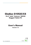
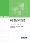
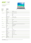
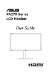
EmQ-i2301
Qseven® CPU Module
User’s Manual
Version 1.0
2014.08
I
This page is intentionally left blank.
- II -
Revision History
Version
Release Time
Description
1.0
August, 2014
Initial release
-i-
Contents
Contents
Revision History..................................................................................i
Contents..............................................................................................ii
Preface...............................................................................................iv
Copyright Notice..................................................................................... iv
Declaration of Conformity....................................................................... iv
CE.................................................................................................... iv
FCC Class A..................................................................................... v
RoHS................................................................................................ v
SVHC / REACH............................................................................... vi
Warning................................................................................................... vi
Replacing the Lithium Battery................................................................. vi
Technical Support................................................................................... vi
Warranty.................................................................................................vii
Chapter 1 - Introduction.....................................................................1
1.1. The Product...................................................................................... 2
1.2. About this Manual............................................................................. 2
1.3. Specifications.................................................................................... 3
1.4. Inside the Package........................................................................... 4
1.5. Ordering Information......................................................................... 5
1.6. Driver Installation Note...................................................................... 6
Chapter 2 - Board Overview..............................................................9
2.1. Board Dimensions........................................................................... 10
2.2. Block Diagram................................................................................. 11
2.3. Connector Pin Definition................................................................. 12
Chapter 3 - BIOS...............................................................................15
3.1. Main................................................................................................ 17
3.2. Advanced........................................................................................ 18
3.2.1. Boot Configuration................................................................ 20
3.2.2. PCI Express Configuration................................................... 20
3.2.3. USB Configuration................................................................ 21
3.2.4. Audio Configuration.............................................................. 21
3.2.5. LPSS & SCC Configuration.................................................. 22
3.2.6. Miscellaneous Configuration................................................. 23
3.2.7. Security Configuration.......................................................... 23
3.2.8. Video Configuration.............................................................. 24
3.2.9. SATA Configuration............................................................... 26
3.2.10. ACPI Table/Feature Control................................................ 26
3.2.11. LM90 Thermal Sensor........................................................ 27
3.2.12. SIO FINTEK81866 ............................................................. 27
- ii -
Contents
3.3. Security........................................................................................... 28
3.4. Power.............................................................................................. 29
3.4.1 Advanced CPU Control.......................................................... 30
3.4. Boot................................................................................................. 32
3.5. Exit.................................................................................................. 34
- iii -
Preface
Preface
Copyright Notice
All Rights Reserved.
The information in this document is subject to change without prior notice in
order to improve the reliability, design and function. It does not represent a
commitment on the part of the manufacturer.
Under no circumstances will the manufacturer be liable for any direct, indirect,
special, incidental, or consequential damages arising from the use or inability
to use the product or documentation, even if advised of the possibility of such
damages.
This document contains proprietary information protected by copyright. All rights
are reserved. No part of this manual may be reproduced by any mechanical,
electronic, or other means in any form without prior written permission of the
manufacturer.
Declaration of Conformity
CE
The CE symbol on your product indicates that it is in compliance with the
directives of the Union European (EU). A Certificate of Compliance is available
by contacting Technical Support.
This product has passed the CE test for environmental specifications when
shielded cables are used for external wiring. We recommend the use of shielded
cables. This kind of cable is available from ARBOR. Please contact your local
supplier for ordering information.
This product has passed the CE test for environmental specifications. Test
conditions for passing included the equipment being operated within an
industrial enclosure. In order to protect the product from being damaged by ESD
(Electrostatic Discharge) and EMI leakage, we strongly recommend the use of
CE-compliant industrial enclosure products.
Warning
This is a class A product. In a domestic environment this product may cause
radio interference in which case the user may be required to take adequate
measures.
- iv -
Preface
FCC Class A
This device complies with Part 15 of the FCC Rules. Operation is subject to the
following two conditions:
(1)This device may not cause harmful interference, and
(2)This device must accept any interference received, including interference that
may cause undesired operation.
NOTE:
This equipment has been tested and found to comply with the limits for a
Class A digital device, pursuant to Part 15 of the FCC Rules. These limits are
designed to provide reasonable protection against harmful interference when the
equipment is operated in a commercial environment. This equipment generates,
uses, and can radiate radio frequency energy and, if not installed and used in
accordance with the instruction manual, may cause harmful interference to radio
communications. Operation of this equipment in a residential area is likely to
cause harmful interference in which case the user will be required to correct the
interference at his own expense.
RoHS
ARBOR Technology Corp. certifies that all components in its products are in
compliance and conform to the European Union’s Restriction of Use of Hazardous Substances in Electrical and Electronic Equipment (RoHS) Directive
2002/95/EC.
The above mentioned directive was published on 2/13/2003. The main purpose of the directive is to prohibit the use of lead, mercury, cadmium, hexavalent chromium, polybrominated biphenyls (PBB), and polybrominated diphenyl
ethers (PBDE) in electrical and electronic products. Member states of the EU
are to enforce by 7/1/2006.
ARBOR Technology Corp. hereby states that the listed products do not contain
unintentional additions of lead, mercury, hex chrome, PBB or PBDB that exceed a maximum concentration value of 0.1% by weight or for cadmium exceed
0.01% by weight, per homogenous material. Homogenous material is defined
as a substance or mixture of substances with uniform composition (such as solders, resins, plating, etc.). Lead-free solder is used for all terminations (Sn(9696.5%), Ag(3.0-3.5%) and Cu(0.5%)).
-v-
Preface
SVHC / REACH
To minimize the environmental impact and take more responsibility to the earth
we live, Arbor hereby confirms all products comply with the restriction of SVHC
(Substances of Very High Concern) in (EC) 1907/2006 (REACH --Registration,
Evaluation, Authorization, and Restriction of Chemicals) regulated by the
European Union.
All substances listed in SVHC < 0.1 % by weight (1000 ppm)
Warning
Single Board Computers and their components contain very delicate
Integrated Circuits (IC). To protect the Single Board Computer and its
components against damage from static electricity, you should always follow the
following precautions when handling it:
1. Disconnect your Single Board Computer from the power source when you
want to work on the inside.
2. Hold the board by the edges and try not to touch the IC chips, leads or
circuitry.
3. Use a grounded wrist strap when handling computer components.
4. Place components on a grounded antistatic pad or on the bag that comes
with the Single Board Computer, whenever components are separated from
the system.
Replacing the Lithium Battery
Incorrect replacement of the lithium battery may lead to a risk of explosion.
The lithium battery must be replaced with an identical battery or a battery type
recommended by the manufacturer.
Do not throw lithium batteries into the trash-can. It must be disposed of in
accordance with local regulations concerning special waste.
Technical Support
If you have any technical difficulties, please do not hesitate to call or e-mail our
customer service.
http://www.arbor.com.tw
E-mail:[email protected]
- vi -
Preface
Warranty
This product is warranted to be in good working order for a period of two years
from the date of purchase. Should this product fail to be in good working order
at any time during this period, we will, at our option, replace or repair it at no
additional charge except as set forth in the following terms. This warranty does
not apply to products damaged by misuse, modifications, accident or disaster.
Vendor assumes no liability for any damages, lost profits, lost savings or any other
incidental or consequential damage resulting from the use, misuse of, or inability to
use this product. Vendor will not be liable for any claim made by any other related party.
Vendors disclaim all other warranties, either expressed or implied, including but
not limited to implied warranties of merchantability and fitness for a
particular purpose, with respect to the hardware, the accompanying product’s
manual(s) and written materials, and any accompanying hardware. This limited
warranty gives you specific legal rights.
Return authorization must be obtained from the vendor before returned
merchandise will be accepted. Authorization can be obtained by calling or faxing
the vendor and requesting a Return Merchandise Authorization (RMA) number.
Returned goods should always be accompanied by a clear problem description.
- vii -
This page is intentionally left blank.
- viii -
1
Chapter 1
Introduction
Chapter 1 - Introduction
-1-
Introduction
1.1. The Product
• Fanless Design
• Soldered Onboard Intel® Atom™ Processor E3800 family
• Intel® i210IT PCIe GbE controller
• Dual Channels 24-bit LVDS, DDI Port
• Extended Operating Temp.: -20 ~ 70ºC
1.2. About this Manual
This manual is intended for experienced users and integrators with hardware
knowledge of computers. If you are not sure about the description in this manual,
consult your vendor before further handling.
We recommend that you keep one copy of this manual for the quick reference
for any necessary maintenance in the future. Thank you for choosing ARBOR
products.
-2-
Introduction
1.3. Specifications
Form Factor
Qseven® CPU Module
CPU
Soldered onboard Intel® Atom™ Processor E3825
dual-core 1.33GHz or E3845 quadcore 1.91GHz
System Memory
Soldered onboard 2GB / 4GB DDR3L SDRAM
VGA/ LCD Controller SoC Integrated Intel® Gen7 graphic
Ethernet controller
1 x Intel® i210IT PCIe GbE controller
Audio
HD Audio Link
BIOS
Insyde UEFI BIOS
Serial ATA
2 x Serial ATA ports w/ 300MB/s HDD transfer rate
Universal Serial Bus 8 x USB 2.0 ports
Storage
Soldered onboard 16GB eMMC (Optional)
LCD: Dual Channels 24-bit LVDS, resolution up to
1920x1200
Graphics Interface
Analog RGB signals (via Qseven® GF reserved pin)
1 x DDI port
Expansion Bus
3 x PCIe x1 lanes, SDIO, I2C
Operating Temp.
-20ºC ~ 70ºC (-4ºF ~ 158ºF) for EmQ-i2301
Watchdog Timer
1~ 255 levels Reset
Dimension (L x W)
70 x 70 mm (2.76” x 2.76”)
-3-
Introduction
1.4. Inside the Package
Before starting with the installation, make sure the following items are shipped.
If any of the items is missing or appears damaged, contact your local dealer or
distributor.
1 x EmQ-i2301 Qseven® CPU Module
1 x Driver CD
1 x Quick Installation Guide
-4-
Introduction
1.5. Ordering Information
EmQ-i2301-E3825-2G
Intel® Atom™ Processor Bay Trail-I E3825 Qseven® CPU
module w / 2GB memory soldered on module
EmQ-i2301-E3845-2G
Intel® Atom™ Processor Bay Trail-I E3845 Qseven® CPU
module w / 2GB memory soldered on module
EmQ-i2301-E3825-4G(BTO)
Intel® Atom™ Processor Bay Trail-I E3825 Qseven® CPU
module w / 4GB memory soldered on module
EmQ-i2301-E3845-4G(BTO)
Intel® Atom™ Processor Bay Trail-I E3845 Qseven® CPU
module w / 4GB memory soldered on module
EmQ-i2301D-E3825-2G(BTO)
Intel® Atom™ Processor Bay Trail-I E3825 Qseven® CPU
module w / eMMC16GB and 2GB memory soldered on
module
EmQ-i2301D-E3845-2G(BTO)
Intel® Atom™ Processor Bay Trail-I E3845 Qseven® CPU
module w / eMMC16GB and 2GB memory soldered on
module
EmQ-i2301D-E3825-4G(BTO)
Intel® Atom™ Processor Bay Trail-I E3825 Qseven® CPU
module w / eMMC16GB and 4GB memory soldered on
module
EmQ-i2301D-E3845-4G(BTO)
Intel® Atom™ Processor Bay Trail-I E3845 Qseven® CPU
module w / eMMC16GB and 4GB memory soldered on
module
HS-0662-F1
Heat spreader
HS-0000-W3
Universal evaluation Heatsink for Qseven® CPU module
PBQ-3000
Qseven® EPIC evaluation board
CBK-06-3000-00
Cable kit
1 x USB cable
1 x USB2 cable
2 x Serial port cables
1 x SATA cable
1 x SATA power cable
-5-
Introduction
1.6. Driver Installation Note
The CPU board supports Windows 7 and Windows 8/8.1. Find the necessary
drivers on the CD that comes with your purchase. For different OS, the driver/
utility installation may vary slightly, but generally they are similar.
Find the drivers on CD by the following paths:
Windows 8.1
Driver
Audio
Chipset
Ethernet
Path
\Audio\32 bit
\Audio\64 bit
\Chipset\32bit\Chipset Kit 57833 _32
\Chipset\64bit\Chipset Kit 57833 _64
\Ethernet\Intel\32bit\LAN 18.8.1 _32
\Ethernet\Intel\64bit\LAN 18.8.1 _64
GPIO
\GPIO\Kit 100882 20140211 windows 8.1 64\GPIO
I2C
\I2C\Kit 100882 20140211 windows 8.1 64\I2C
Graphics
\Graphic\Win8.1\32bit\Kit 57832_win8_32bit_2013-1202\Win32
\Graphic\Win8.1\64bit\Kit 5783364_win8_8.1 _64_2013-1202\win64
MBI
\MBI\MBI Kit 58443 20140106_windows 8_8.132_64
TXE
\TXE\TXE Kit 100885
Windows 8
Driver
Audio
Chipset
Ethernet
Graphics
Path
\Audio\32 bit
\Audio\64 bit
\Chipset\32bit\Chipset Kit 57833 _32
\Chipset\64bit\Chipset Kit 57833 _64
\Ethernet\Intel\32bit\LAN 18.8.1 _32
\Ethernet\Intel\64bit\LAN 18.8.1 _64
\Graphic\Win8.1\32bit\Kit 57832_win8_32bit_2013-1202\Win32
\Graphic\Win8.1\64bit\Kit 5783364_win8_8.1 _64_2013-1202\win64
MBI
\MBI\MBI Kit 58443 20140106_windows 8_8.132_64
TXE
\TXE\TXE Kit 100885
WINUSB
\WINUSB Driver
-6-
Introduction
Windows 7
Driver
Audio
Chipset
Ethernet
Graphics
Path
\Audio\32 bit
\Audio\64 bit
\Chipset\32bit\Chipset Kit 57833 _32
\Chipset\64bit\Chipset Kit 57833 _64
\Ethernet\Intel\32bit\LAN 18.8.1 _32
\Ethernet\Intel\64bit\LAN 18.8.1 _64
\Graphic\win 7\Kit 101116 20140402 32bit\Intel_EMGD.WIN7_PC_
Version_36_15_0_1073
\Graphic\win 7\KIT 101117 20140402 64bit\Intel_EMGD.WIN7_PC_
Version_37_15_0_1073
GPIO
\GPIO\windows 7 32_64\Intel Atom E3800 Win7 IO Drivers_Gold_
v1.0 package 501232_ 20140211
I2C
\I2C\windows 7 32_64\Intel Atom E3800 Win7 IO Drivers_Gold_v1.0
package 501232_ 20140211
TXE
\TXE\TXE Kit 100885
USB3.0
\USB3.0\SetupUSB3
WINUSB
\WINUSB Driver
-7-
This page is intentionally left blank.
-8-
2
Chapter 2
Board
Overview
Chapter 2 - Board Overview
-9-
Board Overview
2.1. Board Dimensions
2.50
15.77
39.27
56.50
70.00
70.00
52.00
36.58
35.94
22.86
18.00
1.20
3.00
67.00
Unit:mm
- 10 -
Board Overview
2.2. Block Diagram
DDR3L-1066/1333MHz (up to 4GB)
1 x eDP port
Onboard DDR3L
2GB SDRAM
Dual Channels 24-bit LVDS
NXP
PTN3460
Analog R.G.B.(to Q7 RSV pin)
1 x DDI port (DDI1)
1 x HSIC
Intel®
Atom™
Processor
E3800
family
SMSC
USB4604
4 x USB 2.0 Ports(4~7)
3 x PCIex1
1 x PCIe x 1
Giga LAN
Intel i210IT
SATA0
SATA1
SDIO
LPC I/F
HD Audio Link
I2C
eMMC 4.5
Onboard eMMC
up to 16GB
- 11 -
GbE LAN
Q7 Golden Finger
4 x USB 2.0 host ports (0~3)
Board Overview
2.3. Connector Pin Definition
Pin Signal
Pin Signal
Pin Signal
Pin Signal
1
GND
2
GND
65
HDA_SDI
66
I2C_CLK
3
GBE_MDI3-
4
GBE_MDI2-
67
HDA_SDO
68
I2C_DAT
5
GBE_MDI3+
6
GBE_MDI2+
69
THRM#
70
WDTRIG#
7
GBE_LINK100#
8
GBE_LINK1000#
71
THRMTRIP#
72
WDOUT (N/C)
9
GBE_MDI1-
10
GBE_MDI0-
73
GND
74
GND
USB_P7-
76
USB_P6-
11
GBE_MDI1+
12
GBE_MDI0+
75
13
GBE_LINK#
14
GBE_ACT#
77
USB_P7+
78
USB_P6+
15
GBE_CTREF
16
SUS_S5#
79
USB_6_7_OC#
80
USB_4_5_OC#
17
WAKE#
18
SUS_S3#
81
USB_P5-
82
USB_P4-
USB_P5+
84
USB_P4+
19
SUS_STAT#
20
PWRBTN#
83
21
SLP_BTN#
22
LID_BTN#
85
USB_2_3_OC#
86
USB_0_1_OC#
23
GND
24
GND
87
USB_P3-
88
USB_P2-
KEY
89
USB_P3+
90
USB_P2+
KEY
25
GND
26
PWGIN
91
USB_HOST_PRES# (N/C)
92
USB_HC_SEL (N/C)
27
BATLOW#
28
RSTBTN#
93
USB_P1-
94
USB_P0-
29
SATA0_TX+
30
SATA1_TX+
95
USB_P1+
96
USB_P0+
97
GND
98
GND
31
SATA0_TX-
32
SATA1_TX-
33
SATA_ACT#
34
GND
99
LVDS_A0+
100
LVDS_B0+
35
SATA0_RX+
36
SATA1_RX+
101
LVDS_A0-
102
LVDS_B0-
37
SATA0_RX-
38
SATA1_RX-
103
LVDS_A1+
104
LVDS_B1+
LVDS_A1-
106
LVDS_B1-
39
GND
40
GND
105
41
BIOS_DISABLE#
42
SDIO_CLK#
107
LVDS_A2+
108
LVDS_B2+
43
SDIO_CD#
44
SDIO_LED (N/C)
109
LVDS_A2-
110
LVDS_B2-
45
SDIO_CMD
46
SDIO_WP
111
LVDS_PPEN
112
LVDS_BLEN
47
SDIO_PWR#
48
SDIO_DAT1
113
LVDS_A3+
114
LVDS_B3+
49
SDIO_DAT0
50
SDIO_DAT3
115
LVDS_A3-
116
LVDS_B3-
51
SDIO_DAT2
52
SDIO_DAT5 (N/C)
117
GND
118
GND
LVDS_A_CLK+
120
LVDS_B_CLK+
53
SDIO_DAT4 (N/C)
54
SDIO_DAT7 (N/C)
119
55
SDIO_DAT6 (N/C)
56
RSVD (N/C)
121
LVDS_A_CLK-
122
LVDS_B_CLK-
57
GND
58
GND
123
LVDS_BLT_CTRL
124
RSVD (N/C)
59
HDA_SYNC
60
SMB_CLK
125
LVDS_DID_DAT
126
CRT_DDC_Data
LVDS_DID_CLK
128
CRT_DDC_CLK
CAN0_TX (N/C)
130
CAN0_RX (N/C)
61
HDA_RST#
62
SMB_DAT
127
63
HDA_BITCLK
64
SMB_ALERT#
129
- 12 -
Board Overview
Pin Signal
Pin Signal
Pin Signal
Pin Signal
131
DP1_TX3_P
132
SDVO_INT+ (N/C)
197
GND
198
GND
133
DP1_TX3_N
134
SDVO_INT- (N/C)
199
SPI_MOSI
200
SPI_CS0#
135
GND
136
GND
201
SPI_MISO
202
SPI_CS1# (N/C)
137
DP1_TX1_P
138
DP1_AUX_C_P
203
SPI_SCLK
204
CRT_RED
139
DP1_TX1_N
140
DP1_AUX_C_N
205
VCC_5V_SB
206
VCC_5V_SB
141
GND
142
GND
207
CRT_VSYNC
208
CRT_GREEN
143
DP1_TX2_P
144
SDVO_TVCLKIN+ (N/C)
209
CRT_HSYNC
210
CRT_BLUE
145
DP1_TX2_N
146
SDVO_TVCLKIN- (N/C)
211
+5V
212
+5V
147
GND
148
GND
213
+5V
214
+5V
149
DP1_TX0_P
150
DP1_AUX_N
215
+5V
216
+5V
151
DP1_TX0_N
152
DP1_AUX_P
217
+5V
218
+5V
153
HDMI_HPD#
154
DP_HPD#
219
+5V
220
+5V
155
PCIE_CLK_REF+
156
PCIE_WAKE#
221
+5V
222
+5V
157
PCIE_CLK_REF-
158
PCIE_RST#
223
+5V
224
+5V
159
GND
160
GND
225
+5V
226
+5V
161
PCIE3_TX+ (N/C)
162
PCIE3_RX+ (N/C)
227
+5V
228
+5V
163
PCIE3_TX- (N/C)
164
PCIE3_RX- (N/C)
229
+5V
230
+5V
165
GND
166
GND
167
PCIE2_TX+
168
PCIE2_RX+
169
PCIE2_TX-
170
PCIE2_RX-
171
EXCD0_PERST#
172
EXCD1_PERST#
173
PCIE1_TX+
174
PCIE1_RX+
175
PCIE1_TX-
176
PCIE1_RX-
177
EXCD0_CPPE#
178
EXCD1_CPPE#
179
PCIE0_TX+
180
PCIE0_RX+
181
PCIE0_TX-
182
PCIE0_RX-
183
GND
184
GND
185
LPC_AD0
186
LPC_AD1
187
LPC_AD2
188
LPC_AD3
189
LPC_CLK
190
LPC_FRAME#
191
SERIRQ
192
LPC_LDRQ# (N/C)
193
VCC_RTC
194
SPKR
195
FAN_TACHOIN (N/C)
196
FAN_PWMOUT (N/C)
- 13 -
This page is intentionally left blank.
- 14 -
3
Chapter 3
BIOS
Chapter 3 - BIOS
- 15 -
BIOS
The BIOS Setup utility is featured by Insyde BIOS to configure the system
settings stored in the system’s BIOS ROM. Insyde BIOS is activated once the
computer powers on.
After entering the utility, use the left/right arrow keys to navigate between the top
menus and use the down arrow key to access one.
Menu
Main
Advanced
Security
Power
Boot
Exit
Description
See 3.1. Main on page 17.
See 3.2. Advanced on page 18.
See 3.3. Security on page 28.
See 3.3. Security on page 28.
See 3.4. Boot on page 32.
See 3.5. Exit on page 34.
NOTE: For system stability and performance, this BIOS utility is constantly improved. The screenshots demonstrated and descriptions hereinafter are for reference only and may not exactly meet what is presented onscreen.
- 16 -
BIOS
3.1. Main
The Main menu displays some BIOS info and features the settings of System
Date and System Time.
The BIOS info displayed is:
Info Item
BIOS Version
Project name
Build Date and Time
Platform firmware
Information
Description
Delivers the computer’s BIOS version.
Delivers the name of the project
Delivers the date and time when the BIOS Setup utility was created/
updated.
Delivers the Platform firmware Information
The featured settings are:
Setting
Language
System Time
System Date
Description
Select the current default language used by the InsydeH20
Sets system time.
Sets system date.
- 17 -
BIOS
3.2. Advanced
The Advanced menu controls the system’s CPU, IDE, Super IO, AHCI and
USB. It also helps users monitor hardware health.
.
- 18 -
BIOS
The featured submenus are:
Submenu
Boot Configuration
PCI Express Configuration
USB Configuration
Audio Configuration
LPSS & SCC Configuration
Miscellaneous Configuration
Security Configuration
Video Configuration
SATA Configuration
ACPI Table/Feature Control
LM90 Thermal Sensor
SIO FINTEK81866
Description
See 3.2.1. Boot Configuration on page 20.
See 3.2.2. PCI Express Configuration on page20.
See 3.2.3. USB Configuration on page 21.
See 3.2.4. Audio Configuration on page 21.
See 3.2.5. LPSS & SCC Configuration on page 22.
See 3.2.6. Miscellaneous Configuration on page 23.
See 3.2.7. Security Configuration on page 23.
See 3.2.8. Video Configuration on page 24.
See 3.2.9. SATA Configuration on page 26.
See 3.2.10. ACPI Table/Feature Control on page 26.
See 3.2.11. LM90 Thermal Sensor on page 27.
See 3.2.12. SIO FINTEK81866 on page 27.
- 19 -
BIOS
3.2.1. Boot Configuration
Setting
Numlock
Description
Select Power-on state for Num lock
3.2.2. PCI Express Configuration
Configures PCI Express by the following settings:
Setting
Description
``
``
PCI Express Root Port
Enables/disables this PCIe port.
PCIe Speed
Options are: Auto, Gen 1, Gen 2
Auto is the default.
ASPM Support
Options are:
Disable : disables ASPM
L0s : force all links to L0s state
L1 : force all links to L1 state
L0sL1 : force all links to L0s+L1 state
Auto : BIOS auto configure
PCI Express Root
Port
1/2/3
``
On Board LAN
Configuration
Enables/Disables On Board LAN Configuration
- 20 -
BIOS
3.2.3. USB Configuration
Select this submenu to view the status of the USB ports and configure USB
features.
The featured settings are:
Setting
XHCI Pre-Boot Mode
Support
xHCI Mode
XCHI Controller
USB2 Link Power
Management
XCHI Streams
USB OTG Support
USB VBUS
USB Per-Port Control
Description
Enables/Disables XHCI Pre-Boot mode support
Set the mode of operation of xHCI controller
Options are Disabled/Enabled/Auto/Smart Auto(default)
Enables/Disables XHCI controller
Enables/Disables USB2 Link Power Management.
Enables/disables XHCI Stream
Enables/disables USB OTG Support
Turn ON/OFF USB VBUS. Turn ON in HOST mode,
and turn OFF in OTG device mode.
Enables/Disables USB Per-port control
3.2.4. Audio Configuration
The featured settings are:
Setting
Audio Controller
Azalia VCi Enable
Description
Enables/Disables Azalia Controller
Enables/Disables Virtual Channel 1 of Audio Controller
Azalia HDMI Codec
Enables/Disables Internal HDMI codec for Azalia
- 21 -
BIOS
3.2.5. LPSS & SCC Configuration
The featured settings are:
Setting
LPSS & SCC Device
Mode
Description
Set the mode of LPSS & SCC Device
Options are ACPI mode(default)/PCI mode
OS Selection
Set the mode of OS Selection
Options are Windows(default)/Android
SCC eMMC Boot
Controller
eMMC Secure Erase
SCC SDIO Support
SCC SD Card Supprt
SDR25 Capability
Support for SDCard
DDR50 Capability
Support for SDCard
LPSS DMA #1 Support
LPSS DMA #1 Support
LPSS I2C #1 Support
Set the mode of eMMC Boot mode
Options are Disable/ Auto Detect(Default)/ eMMC 4.41/ eMMC 4.5
Enables/disables eMMC Secure Erase
Enables/disables SCC SDIO Support
Enables/disables SCC SD Card Supprt
Enables/disables SDR25 Capability Support for SDCard
Enables/disables DDR50 Capability Support for SDCard
Enables/disables LPSS DMA #1 Support
Enables/disables LPSS DMA #2 Support
Enables/disables LPSS I2C #1 Support
- 22 -
BIOS
3.2.6. Miscellaneous Configuration
The featured settings are:
Setting
Description / Available Options
HPET - HPET support
Enables/Disables HPET support in Windows XP
State After G3
Set the state of System when power is re-applied after a Power
failure (G3 state)
Options are S0 State(default)/S5 State
Clock Spread Spectrum
Enables/Disables Clock Spread Spectrum
Exl
Enables/Disables Exl
Bios Lock
Enables/Disables BIOS SPI region write protect
PCI MMIO Size
Set the Size of PCI MMIO
Options are 2G(default)/0.75G/1G/1.25G/1.5G
PCI Express Dynamic
Clock Gating
Enables/Disables PCI Express Dynamic Clock Gating
Force Legacy Free
Enables/Disables Force Legacy Free (Force Disable KBC)
3.2.7. Security Configuration
The featured settings are:
Submenu/Setting
TXE
TXE HMRFP0
TXE Firmware Update
TXE EOP Message
Description
Enables/Disables TXE
Enables/Disables TXE HMRFP0
Enables/Disables Firmware Update
Enables/Disables Sending EOP Message Bofore OS
TXE Unconfiguration
Perform
Enables/Disables TXE Temporary Disable function
- 23 -
BIOS
3.2.8. Video Configuration
Configure video settings
The featured setting is:
3.2.8.1 Video Configuration
Setting
Description
Set Logo & SCU Resolution.
Logo & SCU Resolution
Options are Auto/640 x480/800 x 600/1024 x 768
3.2.8.2 VBT Hook Configuration
Setting
Configure CRT as
CRT EDID Support
Configure DDI0 as
Configure DDI1 as
Configure eDP Panel
Number as
LFP EDID Support
EFP EDID Support
Description
Set the option of CRT.
Options are Default / CRT / No Device
Enables/Disables CRT EDID Support
Set the option of DDI0.
Options are Default/DisplayPort/ HDMI/DVI /DisplayPort
with HDMI/DVI Compatible / No Device
Set the option of DDI1.
Options are Default/ LVDS/ DisplayPort/ HDMI/DVI /
DisplayPort with HDMI/DVI Compatible / No Device
Set the option of VBIOS eDP Panel Number.
Options are 1,2,3,4,5,6,7,8,9,10,11,12,13,14,15,16.
Enables/Disables LFP EDID Support
Enables/Disables EFP EDID Support
3.2.8.3 PTN3460 (eDP to LVDS) Configuration
Setting
PTN3460 Output
Format
PTN3460 EDID Table
Description
Set the Output Format of PTN3460.
Options are (00) VESA (24bpp) / (01) VESA or JEIDA
(18bpp) / (10) JEIDA (24bpp) / (11) JEIDA (24bpp)
Set the EDID Table of PTN3460.
3.2.8.4 GOP Configuration
Setting
GOP Brightness Level
GOP Driver
Description
Set the Brightness Level of GOP.
Enables/Disables GOP Driver
- 24 -
BIOS
3.2.8.5 IGD Configuration
Setting
Intergrated Graphics
Device
Description
Enables/disables Intergrated Graphics Device.
Set IGD or PCI graphic device as the Primary Display.
Options are Auto/IGD/PCie.
RC6 (Render Standby) Enables/Disables Render standby support.
PAVC
Enables/disables Protected Audio Video control
Power Managment
Enables/disables Power mangement lock.
lock
DOP CG
Enables/disables DOP Clock gating.
Set the GTT Size
GTT Size
Options are 1MB/2MB
Set the Aperture size
Apeture Size
Options are 128MB/256MB/512MB
IGD-DVMT PreSet the DVMT5.0 Pre-Allocated (Fixed) Graphics Memory
Allocated
size used by the IGD.
IGD-DVMT total Gfx
Set the size of DVMT 5.0 used by IGD
Mem
IGD Turbo
Enables/disables IGD Turbo
IGD Thermal
Enables/disables IGD Thermal
Spread Spectrum
Enables/disables Spread Spectrum clock
clock
Primary Display
3.2.8.6 IGD- LCD Control
Setting
Force Lid Status
BIA
ALS Support
IGD Flat Panel
IGD Boot Type
Panel Scaling
GMCH BLC Control
Description
Set mode of as the Primary Display.
Options are ON (default) / OFF / Auto.
Set the mode of BIA.
Options are Auto (default) /Disabled / Level 1 /Level 2 /Level
3 /Level 4 /Level 5.
Enables/Disables ALS support.
Set resolution of IGD Flat Panel.
Set the Boot Type of IGD
Set the Scaling of Panel
Options are Auto(default) / Centering / Stretching.
Set the mode of GMCH BLC Control
Options are Auto(default) / PWM-Inverted / GMBus-Inverted
/ PWM-Normal / GMBus-Normal
- 25 -
BIOS
3.2.9. SATA Configuration
Select this submenu to configure the SATA controller and HD.
Setting
Description
Enables/disables the present SATA controller.
SATA Controller(s)
Enabled is the default.
SATA Test Mode
Enables/disables the SATA test mode.
Configures how to sun the SATA drives.
Configures SATA Mode
Options available are AHCI (default) and IDE.
SATA Port 0 Hot Plug Enables/disables hot-pluggable feature for the SATA
Capability
port.
SATA Port 1 Hot Plug Enabled is the default.
Capability
SATA Port 0 Connect Enables/disables the SATA port connect to an ODD
to an ODD
If enabled, when you connect an ODD to a SATA port.
The software auto detection for media insert and tray
SATA Port 1 Connect will be enabled.
to an ODD
Disabled is the default.
Serial ATA Port 0
Delivers the SATA port Media information and Security
Mode.
Serial ATA Port 1
3.2.10. ACPI Table/Feature Control
Setting
FACP - RTC S4 Wakeup
APIC - IO APIC Mode
DSDT - ACPI S3
DSDT - ACPI S4
BGRT - ACPI BGRT
Description
This function will be available only when ACPI is enabled.
Enables/disables S4 Wakup from RTC.
This item is valid only for WIN2K and WINXP. Also, a fresh
install of the OS must occur when APIC mode is desired.
Enables/disables the APIC mode
Enables/disables ACPI S3 state
Enables/disables ACPI S4 state
Enables/disables ACPI BGRT Table
- 26 -
BIOS
3.2.11. LM90 Thermal Sensor
3.2.12. SIO FINTEK81866
Configures SIO by the following settings:
Setting
Power Loss mode
Description
Set the state of Power Loss mode
Options are Always On(default)/Always Off
``
Serial Port
A/B/C/D
``
``
Serial Port
Enables/disables the Serial port.
Base I/O Address
Setup the Base I/O Address of the Serial Port.
Interrupt
Setup the Interrupt of the Serial Port
- 27 -
BIOS
3.3. Security
The Security menu sets up the password for the system’s administrator account.
Once the administrator password is set up, this BIOS Setup utility is limited to
access and will ask for the password each time any access is attempted.
The featured setting is:
Setting
Set Supervisor
Password
Description
To set up an administrator password:
1. Select Set Supervisor Password.
An Create New Password dialog then pops up
onscreen.
2. Enter your desired password that is no less than 3
characters and no more than 20 characters.
3. Hit [Enter] key to submit.
- 28 -
BIOS
3.4. Power
The Power menu sets up the power option of system
The featured setting is:
Setting
Advanced
CPU Control
Wake on PME
S5 Long run
test
Description
See 3.4.1 Advanced CPU Control on page 30
Enables or diables Wake on PME.
Determines the action taken when the system power is off and a PCI
Power Management Enable wake up event occurs.
If enabled, force the system to enable RTC S5 wake up, even if OS
disable it. Support ipwrtest to do RTC S5 wakeup.
Options are Enabled/Disabled.
- 29 -
BIOS
3.4.1 Advanced CPU Control
Setting
Use XD
Capability
Description
Enables or disables processor XD capability.
Sets whether the processor should limit the maximum CPUID input
value to 03h when the operating system queries it upon startup.
Limit CPUID
Select Enabled to allow a processor with Intel® HyperMax value
Threading technology to work with an operating system that
doesn’t support it.
Disabled is the default.
When a processor thermal sensor trips(either core), the PROCHOT#
Bi-Directional
will be driven. If Bi-Directional is enable, external agents can drive
PROCHOT#
PROCHOT# to throttle.
VTX-2
Enables/disables the CPU's VTX-2 function.
TM1 and TM2 Enable/disables TM1/TM2
AESNI Feature Enable/disables AESNI
DTS
Enable/disables CPU Digital Thermal Sensor function.
Active
Set the Number of cores to enable in each processor package.
Processor
Options are ALL/1
Cores
- 30 -
BIOS
P-States(IST)
Boot
Performance
Mode
Turbo Mode
C-States
Enhanced
C-States
Max C-States
S0ix
Enables/disables processor performance states (P-States)
Select the performance state that BIOS will set before OS handoff
Enables/disables processor Turbo mode (EMTTM enabled is
required)
Enables/disables processor idle power saving states (C-states)
Enables/disables P-state transitions to occur in combination with
C-states.
Set the Max CPC state C7/C6/C1
Enables/disables the platform to configure S0ix support.
- 31 -
BIOS
3.4. Boot
The Boot menu configures how to boot up the system such as the configuration
of boot device priority.
The featured settings are:
Setting
Description
Quick Boot
Allow InsydeH20 to Skip certain tests while booting .
This will descrese the time need to boot the system.
Quiet Boot
Disables or enables booting in text mode.
PXE boot to LAN
Disables or enables PXE boot to LAN.
Power Up In Standby
Support
Disable or enable Power Up In Standby Support.
Add Boot Option
Position in Boot Order for Shell, Network and
Removables.
Options are First, Last, and Auto.
APCI Selection
Select boot to Acpi 3.0/Acpi 1.0B
Options are Acpi 1.0B/Acpi 3.0/Acpi 4.0/Acpi 5.0
- 32 -
BIOS
USB Boot
Disables or enables booting to USB boot devices.
Timeout
Set the waiting seconds before booting the default boot
selection
Automatic Failover
Enables/disables the Automatic Failover.
- 33 -
BIOS
3.5. Exit
The Save & Exit menu features a handful of commands to launch actions
from the BIOS Setup utility regarding saving changes, quitting the utility and
recovering defaults.
The features settings are:
Setting
Exit Saving Changes
Save Changes Without Exit
Description
Saves the changes and quits the BIOS Setup utility.
Save Changes but does not quit the BIOS.
Exit Discard Changes
Quits the BIOS Setup utility without saving the
change(s).
Load Optimal Defaults
Restores all settings to defaults.
This is a command to launch an action from the
BIOS Setup utility rather than a setting.
Load Custom Default
Load custome default values
Save Custom Default
Save current setting as custome default
Discard Changes
Discard all changes without Exit.
- 34 -