1
Master Oscillator Power Amplifier SLD System MOPA-SLD-850
Operator’s Guide
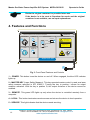
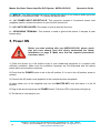
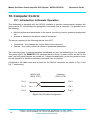
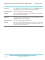
6 – EMISSION ON/OFF. This button toggles between activation and deactivation of the output
emission. When the light is green, emission is activated.
7 – OUTPUT APERTURE. This socket is the optical output of the device. The optical patch
cable supplied with the device is connected here.
8 – PROTECTIVE CAP. This cap is used to protect the optical output from dust and dirt. Always
reattach this cap when the device is not in use.
9 – REMOTE INTERLOCK (Laser Safety Measure). This is used to inform the operator that the
terminals of the remote interlock connector are open-circuited. When this happens, the LED
illuminates red.
MOD IN
3
RS - 232
1
TM
SUPERLUM
www.superlumdiodes.com
TTL
1 kOhm
REMOTE
INTERLOCK
2
MOPA SLD System
P/N: MOPA-SLD-850
SERIAL No: #####
RoHS
COMPLIANT
2002/95/EC
FUSE: 2A
6
5
AC 104-126V; 50-60Hz
FUSE
4
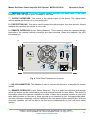
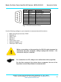
Fig. 4: Rear-Panel Features and Controls
1 – RS-232 CONNECTOR. This adapter is used to connect the device to a computer for remote
access.
2 – REMOTE INTERLOCK (Laser Safety Measure). This is an audio monophonic jack through
which the device can be connected to your local external controls for laser safety. The device is
inoperable unless the interlock connection is made. If there are no external controls in your local
laser safety system or if the use of these controls is not essential for you, the appropriate shortcircuited connector (supplied) must be installed to the rear-panel remote interlock jack. With this
connector installed, you will be able to use the device independently of your local laser safety
system.
Superlum, Unit B3, Fota Point Enterprise Park, Carrigtwohill, Co. Cork, Ireland.
Phone: +353 21 4533666, Fax: +353 21 4533026, E-mail: [email protected].
www.superlumdiodes.com
13