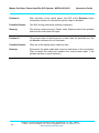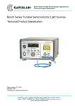
1
SUPERLUM Master Oscillator Power Amplifier SLD System MOPA-SLD-850 Operator’s Guide Master Oscillator Power Amplifier SLD System MOPA-SLD-850 Operation Manual The contents of this manual may be changed without prior notice. Superlum, Unit B3, Fota Point Enterprise Park, Carrigtwohill, Co. Cork, Ireland. Phone: +353 21 4533666, Fax: +353 21 4533026, E-mail: [email protected]. www.superlumdiodes.com Master Oscillator Power Amplifier SLD System MOPA-SLD-850 Operator’s Guide Document Information Related Device Versions: MOPA-SLD-850 Document Data: 02-07-2015 Document Revision: 1.3.1 2 Superlum, Unit B3, Fota Point Enterprise Park, Carrigtwohill, Co. Cork, Ireland. Phone: +353 21 4533666, Fax: +353 21 4533026, E-mail: [email protected]. www.superlumdiodes.com Master Oscillator Power Amplifier SLD System MOPA-SLD-850 Operator’s Guide Table of Contents Page Warranty and Limitations ........................................................................ 4 Safety Symbols and Terms .................................................................... 5 General Safety Information ..................................................................... 6 Laser Safety Information ........................................................................ 7 1. Description .......................................................................................... 9 2. Purposes and Scope ........................................................................ 11 3. Unpacking and Inspection ................................................................ 11 4. Features and Functions .................................................................... 12 5. Power ON ......................................................................................... 14 6. Getting Started ................................................................................. 15 7. Modulation Mode .............................................................................. 16 8. Power OFF ....................................................................................... 17 9. Routine Maintenance and Recommendations.................................. 17 10. Computer Control ........................................................................... 18 10.1. Introduction to Remote Operation ............................................. 18 10.2. Data Communication Protocol .................................................. 20 10.3. Remote Command Set ............................................................. 20 10.3.1. Identification Query ............................................................. 20 10.3.2. Local/Remote Enable Command ........................................ 21 10.3.3. Local/Remote Check Query ................................................ 22 10.3.4. Optical Output Enable Command ....................................... 22 10.3.5. SLD/SOA Driver Check Query ............................................ 22 10.3.6. Operating Parameters Check Query ................................... 23 11. Troubleshooting Information ........................................................... 25 12. Preparing the Instrument for Shipment ........................................... 27 13. Customer Service & Contact .......................................................... 27 14. Technical Data ................................................................................ 28 Superlum, Unit B3, Fota Point Enterprise Park, Carrigtwohill, Co. Cork, Ireland. Phone: +353 21 4533666, Fax: +353 21 4533026, E-mail: [email protected]. www.superlumdiodes.com 3 Master Oscillator Power Amplifier SLD System MOPA-SLD-850 Operator’s Guide Warranty and Limitations Warranty Superlum warrants the MOPA-SLD-850 Master Oscillator Power Amplifier SLD System for a period of 12 months from the date of shipment. During this warranty period Superlum will repair or exchange any unit proven to be defective. Repairs are warranted for the balance of the original warranty period or at least 90 days. For warranty repairs or service the unit must be returned to Superlum at the customer’s expense. Limitation of Warranty Superlum will not accept liability for any incidental damage caused by the failure of this product. This warranty does not cover: Any defect or damage caused by improper operation: incorrect connections, improper handling of the device etc. Accompanying accessories: optical patch cables, AC power cords, RS-232 cables etc. Disassembly of the instrument or any part of the device without prior approval from Superlum will void the warranty. Statement of Calibration Superlum certifies that this product has been inspected, tested and calibrated to meet its published specifications. 4 Superlum, Unit B3, Fota Point Enterprise Park, Carrigtwohill, Co. Cork, Ireland. Phone: +353 21 4533666, Fax: +353 21 4533026, E-mail: [email protected]. www.superlumdiodes.com Master Oscillator Power Amplifier SLD System MOPA-SLD-850 Operator’s Guide Safety Symbols and Terms This section includes information on the safety symbols used on the product and in the manual, and gives explanations about what they stand for. These symbols and terms indicate precautions you must strictly follow for safe operation of the device. This symbol indicates the field-wiring terminal that must be connected to earth ground before operating the equipment. It is intended for protection against electrical shock, in case of a fault. This warning sign denotes a hazard. It calls attention to a procedure, practice, or the like, which, if not correctly performed or adhered to, could result in personal injury. Do not proceed beyond a warning sign until the indicated conditions are fully understood and met. ! ! This caution sign denotes a hazard. It calls attention to an operating procedure, or the like, which, if not correctly performed or adhered to, could result in damage to or destruction of the entire product or part thereof. Do not proceed beyond a caution sign until the indicated conditions are fully understood and met. This sign denotes important information. It calls attention to procedures, practice, condition or the like, which is essential to highlight. The CE mark shows that the product complies with all relevant European Legal Directives. This warning label denotes laser radiation. RoHS COMPLIANT 2002/95/EC This label means the compliance with the requirement ofthe RoHS Directive (Directive 2002/95/EC). Superlum, Unit B3, Fota Point Enterprise Park, Carrigtwohill, Co. Cork, Ireland. Phone: +353 21 4533666, Fax: +353 21 4533026, E-mail: [email protected]. www.superlumdiodes.com 5 Master Oscillator Power Amplifier SLD System MOPA-SLD-850 Operator’s Guide General Safety Information General Notes and Warnings This operation manual must be read completely before using the device. Incorrect use or handling and any consequences arising from this may damage the device or endanger personnel. The manufacturer declines all liability resulting from incorrect use and handling. Safety Notes Before you switch the device on, make sure that all protective earth terminals, extension cords and autotransformers are connected to a protective earth-grounded receptacle. Any interruptions of the protective grounding conductor or disconnections of the protective earth terminal can make the device dangerous. Do not perform an intentional interruption of the protective grounding conductor. For continued protection against fire hazard, replace the line fuse only with a fuse of the same rating (current, time delay etc.). Do not use repaired fuses or short-circuited fuse holders. Before you switch the device on, verify that the product is set to your power line voltage and the correct fuse is installed. ! Use this equipment only with either the supplied AC power cord or with an equal replacement. Do not use this device with AC power source which is different from that specified on the rear panel of the device. Failure to obey this rule may result in personal injury and can cause permanent damage to the device. Do not open the device as you may damage it. Disassembly of the device will lead to voiding of the warranty. Never operate the instrument at condensing conditions. Have you instrument recalibrated once a year. 6 Superlum, Unit B3, Fota Point Enterprise Park, Carrigtwohill, Co. Cork, Ireland. Phone: +353 21 4533666, Fax: +353 21 4533026, E-mail: [email protected]. www.superlumdiodes.com Master Oscillator Power Amplifier SLD System MOPA-SLD-850 Operator’s Guide Laser Safety Information The light source in this equipment is classified as a Class 3B laser product according to IEC 60825-1 Ed.2.0 2007-03 standard. Table 1: Laser Safety Classification Based on IEC 60825-1 Ed.2.0 2007-03 Model Class MOPA-SLD-850 3B Optical Power (max) 50 mW Operational Mode CW Emitted Beam Wavelength Radiation Angle 850 nm 11.5 deg. Output Aperture Fig. 3 Information about the class of the product can be found on the yellow label on the front panel of the device above the Optical Aperture (see Fig. 3). CLASS 3B LASER PRODUCT – Avoid Exposure To Beam! ! INVISIBLE RADIATION AVOID EXPOSURE TO BEAM CLASS 3B PRODUCT Wavelength: 850 nm Power: 50 mW Light sources assigned to this class are always hazardous for the intra-beam ocular viewing even if an accidental short-time exposure occurs. Viewing them through optical elements with diffuse-reflecting properties is usually safe for the user. ! Using controls, adjustments or operating procedures that are different from those described in this manual may result in radiation exposure hazardous to the user. When the instrument is used with certain optical elements (optical amplifiers, lenses, collimators etc.) that are not supplied with the product as original accessories or the product is integrated into a high-level system, it is strictly recommended to reclassify the final optical system in order to determine the total degree of optical radiation hazard. The reason for this is that the class of laser hazard may higher under these conditions. It is the responsibility of the end-user who performs such integration to provide correct reclassification for the optical system at the final stage. Superlum, Unit B3, Fota Point Enterprise Park, Carrigtwohill, Co. Cork, Ireland. Phone: +353 21 4533666, Fax: +353 21 4533026, E-mail: [email protected]. www.superlumdiodes.com 7 Master Oscillator Power Amplifier SLD System MOPA-SLD-850 Operator’s Guide It is the end-user who is responsible for being aware of possible risk associated with using class 3B laser products as well as being adequately trained for working with such light sources. Superlum is not liable for any personal injury, property damage or other (direct or indirect) damage of any nature caused by personal faults, improper and/or inadequate using of the instrument coming from disregarding the necessary aspects of laser safety. Incorporated into this equipment are the following laser safety features: Key-operated master control Remote interlock connector Enable button with a built-in LED indicator Three-second time delay before the optical output activation Audible and visible warning signals for the optical output activation Protective metal cap for the optical output Laser safety marking 8 Before you start working with the device, please read thoroughly this manual to acquaint yourself with all features for laser safety implemented in this equipment. Superlum, Unit B3, Fota Point Enterprise Park, Carrigtwohill, Co. Cork, Ireland. Phone: +353 21 4533666, Fax: +353 21 4533026, E-mail: [email protected]. www.superlumdiodes.com Master Oscillator Power Amplifier SLD System MOPA-SLD-850 Operator’s Guide 1. Description This manual is an operator's guide for the model MOPA-SLD-850 Master Oscillator Power Amplifier SLD System, a laboratory ultra-high power SLD-based light source, designed and manufactured by Superlum. This light source is a bench top optoelectronic instrument designed to generate incoherent light in 850-nm spectral range with optical power of up to 50 mW from fiber. It is particularly designed to OCT (Optical Coherent Tomography) applications where high levels of optical power are frequently needed. The system is built on the optical scheme known as MOPA – Master Oscillator Power Amplifier. This is a combination of a weak power master-source (called oscillator) with a high-power output booster (called amplifier). This configuration is widely and successfully used in various laser applications in order to boost optical power of a master laser. For the device in question, an SLD-master source is used instead of a laser. A simplified block diagram of the optical scheme of the device is shown in Fig. 1. APC M-SLD ISO Output SOA OPM Fig. 1: Block Diagram of MOPA Configuration (Simplified) M-SLD – Master SLD ISO – Isolator SOA – Semiconductor Optical Amplifier OPM – Optical Power Monitor APC – Automatic Power Control A medium-power SLD used as a master source provides optical power of 6 – 10 mW with a relatively broad spectrum of 10-20 nm centered at 850 nm. After passing through the appropriate optical isolator with isolation of better than –25 dB, this power is raised to a high level of 50 mW by a spectrally matched SOA. The key advantage of such an approach is that the SOA becomes weakly sensitive to optical feedback. This is because the input power of 6-10 mW is high enough to provide SOA operation in deep saturation mode. In this mode, the SOA remains rather insensitive to optical feedback up to –14 dB that corresponds to typical back reflections of 4%, naturally imposed by a normal cleaved fiber tip (Fig. 2). Further increase of this value (to –10 dB) will cause significant reduction of the SOA performance, but without any fatal damage to the SOA emitter. Due to low sensitivity to optical feedback, there is no need to use an optical isolator (as a protective measure) at the output of the SOA. In this situation, substantially lower operating currents are realized. Obviously, the SOA lifetime, thereby, could be prolonged. Superlum, Unit B3, Fota Point Enterprise Park, Carrigtwohill, Co. Cork, Ireland. Phone: +353 21 4533666, Fax: +353 21 4533026, E-mail: [email protected]. www.superlumdiodes.com 9 Master Oscillator Power Amplifier SLD System MOPA-SLD-850 Operator’s Guide 60 50 Optical Power 2 1 3 40 30 20 10 0 0 50 100 150 200 250 300 350 400 SOA Current (mA) Fig. 2: Power-Current Characteristics of SOA 1: SOA without input optical power – "free-running" mode; angle-cleaved fibers 2: 10 mW power of master SLD applied; angle-cleaved output fiber 3: 10 mW power of master SLD applied; normal-cleaved output fiber As well as the mentioned advantages, the other important one is all-PM-fiber design which gives perfect stability of the PER (Polarization Extinction Ratio) under varying conditions of temperature, humidity and long-term usage than conventional SM-based realizations. The device uses Superlum driving electronics that features high stability and reliability for SLD applications. To ensure safe driving, the following protective measures are implemented: the “soft" start of drive current at activation, turn-on transient suppression, protection against overheating and disconnection, and pumping current clamping at a limit level. Both the master SLD and the SOA are operated in constant power mode, which provides better stability of optical power than operation in constant current mode. The device can be operated in pulse modulation mode. With TTL pulses applied to the MOD IN connector on the rear panel, the instrument toggles between activation and deactivation states. The maximum frequency of modulation is 50 kHz. Each instrument is carefully tested at the final stage (including calibration, measurements, shortterm running etc.), and an individual acceptance test report is provided with the device. Detailed information on the MOPA design for SLD applications, including physical estimations and practical results, is available at: http://www.superlumdiodes.com/pdf/Ultra-High-PowerMOPA-SLD-Sources.pdf 10 Superlum, Unit B3, Fota Point Enterprise Park, Carrigtwohill, Co. Cork, Ireland. Phone: +353 21 4533666, Fax: +353 21 4533026, E-mail: [email protected]. www.superlumdiodes.com Master Oscillator Power Amplifier SLD System MOPA-SLD-850 Operator’s Guide 2. Purposes and Scope This guide has been designed to provide you with basic information on how to set up, run and successfully use your MOPA-SLD-850 Master Oscillator Power Amplifier SLD System. Information on the device maintenance and repair (except routine procedures and common recommendations) lies beyond the scope of this document and is not intended for the end-user. This document covers: 1) installation, 2) manual control from the front panel, 3) computer control, 4) routine maintenance and recommendations. Troubleshooting information is also given here. If our documentation does not satisfy your query, further support is available. Please use the following information to contact: Phone: +353 21 4533666 Fax: +353 21 4533026 E-mail: [email protected] 3. Unpacking and Inspection In addition to this manual, the MOPA-SLD-850 includes the following items: One AC power cord One optical patch cable Two keys for the device's master control Remote interlock connector (comes inserted into the rear-panel jack) RS-232 null-modem cable Connectivity software and user manual on the disc Acceptance Test Report (ATR) Make sure that all the above items are present and are in good condition. If any of the items is missing or damaged, please contact Superlum. Keep the shipping materials for the carrier's inspection if any damage is found. ! After transportation in cool weather, store the container at room temperature for about two hours before opening. Avoid sharp changes in temperature – they can cause water condensation on the internal parts of the instrument, most of them are delicate optical components. Any amount of water condensation may affect their performance. Superlum, Unit B3, Fota Point Enterprise Park, Carrigtwohill, Co. Cork, Ireland. Phone: +353 21 4533666, Fax: +353 21 4533026, E-mail: [email protected]. www.superlumdiodes.com 11 Master Oscillator Power Amplifier SLD System MOPA-SLD-850 Operator’s Guide Retain the original container for possible future use. If the device is to be sent to Superlum for repair and the original container is not available, use an equal replacement. 4. Features and Functions Master Oscillator Power Amplifier SLD System MOPA CONTROL REMOTE MASTER KEY O 3 2 OPTICAL OUTPUT Emission Service I SUPERLUM 4 On/Off 5 6 Master SLD Local ! Use FC/APC connectors with narrow keys (2.0 mm) ONLY INVISIBLE RADIATION AVOID EXPOSURE TO BEAM CLASS 3B PRODUCT Wav elength: 850 nm Power: 50 m W SOA POWER 1 REMOTE INTERLOCK Output Aperture 9 7 MOPA SLD 850 8 Fig. 3: Front-Panel Features and Controls 1 – POWER. This button turns the device on and off. When engaged, the blue LED indicator lights up. 2 – MASTER KEY (Laser Safety Measure). This key-operated master control is used as a laser safety measure specified in IEC 60825-1. Turning the key to position I allows for output emission activation. With the key in position O, the output emission of the device cannot be enabled. 3 – REMOTE. This green LED lights up only when the device is controlled remotely from a computer. 4 – LOCAL. This button terminates remote access and returns the device to local operation. 5 – SERVICE. This light indicates that the device needs servicing. 12 Superlum, Unit B3, Fota Point Enterprise Park, Carrigtwohill, Co. Cork, Ireland. Phone: +353 21 4533666, Fax: +353 21 4533026, E-mail: [email protected]. www.superlumdiodes.com Master Oscillator Power Amplifier SLD System MOPA-SLD-850 Operator’s Guide 6 – EMISSION ON/OFF. This button toggles between activation and deactivation of the output emission. When the light is green, emission is activated. 7 – OUTPUT APERTURE. This socket is the optical output of the device. The optical patch cable supplied with the device is connected here. 8 – PROTECTIVE CAP. This cap is used to protect the optical output from dust and dirt. Always reattach this cap when the device is not in use. 9 – REMOTE INTERLOCK (Laser Safety Measure). This is used to inform the operator that the terminals of the remote interlock connector are open-circuited. When this happens, the LED illuminates red. MOD IN 3 RS - 232 1 TM SUPERLUM www.superlumdiodes.com TTL 1 kOhm REMOTE INTERLOCK 2 MOPA SLD System P/N: MOPA-SLD-850 SERIAL No: ##### RoHS COMPLIANT 2002/95/EC FUSE: 2A 6 5 AC 104-126V; 50-60Hz FUSE 4 Fig. 4: Rear-Panel Features and Controls 1 – RS-232 CONNECTOR. This adapter is used to connect the device to a computer for remote access. 2 – REMOTE INTERLOCK (Laser Safety Measure). This is an audio monophonic jack through which the device can be connected to your local external controls for laser safety. The device is inoperable unless the interlock connection is made. If there are no external controls in your local laser safety system or if the use of these controls is not essential for you, the appropriate shortcircuited connector (supplied) must be installed to the rear-panel remote interlock jack. With this connector installed, you will be able to use the device independently of your local laser safety system. Superlum, Unit B3, Fota Point Enterprise Park, Carrigtwohill, Co. Cork, Ireland. Phone: +353 21 4533666, Fax: +353 21 4533026, E-mail: [email protected]. www.superlumdiodes.com 13 Master Oscillator Power Amplifier SLD System MOPA-SLD-850 Operator’s Guide 3 – MOD IN. This SMA connector is used to connect the device to an external pulse generator for operation in modulation mode. TTL pulses are applied here. 4 – AC POWER INPUT RECEPTACLE. This connector accepts a 3-conductor power cord (supplied) used to connect the device to your local AC power line. 5 – AC LINE FUSE HOLDER. This holder is used to hold the line fuse. 6 – GROUNDING TERMINAL. This terminal is used to ground the device. It accepts a male banana plug. 5. Power ON ! Before you start working with your MOPA-SLD-850, please check that you have already read and clearly understood the Safety Information on page 6. Make sure that the required precautions have been taken. 1. Place the device on a flat surface close to your measuring equipment in a location with sufficient ventilation. Make sure the ventilation openings are not obstructed and the optical patch cable can be easily connected. 2. Check that the POWER button is set to the off position. If it is not in the off position, press to release. 3. Connect the AC power cord (supplied) to the rear-panel power receptacle. 4. Insert either one of the supplied keys into the MASTER KEY lock and leave it in the O position. 5. Plug in the device and press the POWER button. The blue LED in the button will light up. 6. The device is now ready to use. 14 Superlum, Unit B3, Fota Point Enterprise Park, Carrigtwohill, Co. Cork, Ireland. Phone: +353 21 4533666, Fax: +353 21 4533026, E-mail: [email protected]. www.superlumdiodes.com Master Oscillator Power Amplifier SLD System MOPA-SLD-850 Operator’s Guide 6. Getting Started 1. Connect the device to your local external controls for laser safety. Use the REMOTE INTERLOCK jack on the rear panel of the device for this connection. If you do not have the external controls for laser, use the short-circuited connector supplied with the device. 2. Connect one end of the optical patch cable to the front-panel Output Aperture; the other, to your measuring equipment (e.g. an optical power meter). To ensure low insertion optical loss at the device output, follow the direction on the optical cable label. 3. Press the POWER button to turn the device on. The Thermo-Electric Cooler (TEC) controllers are activated automatically at power-on. They remain active until the device is turned off. 4. Turn the MASTER KEY clockwise to position I. The device will run an internal test to verify whether or not the remote interlock connection has been made. If the test passes, you can activate the optical output of the device (continue to step 5 to do this). If the test fails, the REMOTE INTERLOCK LED will light up steady red and the device will produce a continuous tone. The alarm signifies that the remote interlock connection is open-circuited. Any attempt to activate the output emission will fail until the remote interlock connection has been made and the alarm is reset. To reset, turn the key to position O and back to position I again. 5. Enable the optical output power by pressing the Emission On/Off button. There will be a three-second delay during which the button will blink and the device will beep. Once the delay has elapsed, the button displays a steady green light and the audible signal is turned off. At this point, the output emission begins. 6. Verify that the output power of the device corresponds to the value listed in the ATR. To keep the end faces of the optical patch cable clean and protected, we strongly recommend that you avoid unnecessary disconnections. Whenever possible, leave the optical cable connected to the device. ! Never use optical connectors different from those specified for the device – they are not designed to use with the device and can seriously damage its optical output. This equipment contains analog circuits of driving electronics that are sensible to temperature changes. Therefore, after turning the device on, the optical power of the device can slightly drift over time. For improved stability, a 30-minute warm-up period is recommended. Superlum, Unit B3, Fota Point Enterprise Park, Carrigtwohill, Co. Cork, Ireland. Phone: +353 21 4533666, Fax: +353 21 4533026, E-mail: [email protected]. www.superlumdiodes.com 15 Master Oscillator Power Amplifier SLD System MOPA-SLD-850 Operator’s Guide 7. Modulation Mode 1. Install an interconnection cable (not supplied) between the MOD IN connector located on the front panel of the device and the output of your external pulse generator. Note that the MOD IN connector is a female SMA type. 2. Prepare the instrument for operation as described in Section 6 (on page 15). 3. Pre-set your pulse generator to the following parameters: Pulse Amplitude: 5 V (TTL), Pulse Repetition Frequency: 50 kHz, Duty Cycle: 50%. 4. Activate the optical output of the MOPA-SLD-850 by pressing the Emission On/Off button. 5. Enable the output of your pulse generator. 6. Observe the waveform of optical power on an oscilloscope using a high-speed fiber-coupled photodetector. Compare the obtained results with those depicted in Fig. 5. Light TTL Fig. 5: Operation in Pulse Modulation Mode (Generator Settings: Pulse Amplitude: 5 V (TTL), Pulse Repetition Frequency: 50 kHz, Duty Cycle: 50%.) 16 Superlum, Unit B3, Fota Point Enterprise Park, Carrigtwohill, Co. Cork, Ireland. Phone: +353 21 4533666, Fax: +353 21 4533026, E-mail: [email protected]. www.superlumdiodes.com Master Oscillator Power Amplifier SLD System MOPA-SLD-850 Operator’s Guide 8. Power OFF 1. If the optical output is active, press the Emission On/Off button to disable. 2. Turn the MASTER KEY control counterclockwise to position O. 3. Depress the POWER button. ! Always disable the optical output before turning the device off. Never unplug the device if the optical output is active. 9. Routine Maintenance and Recommendations In order to ensure accurate and reliable operation of the device, it is very important to clean ferrules of the output optical fiber. Dirt, dust and oil inside the connector ports may scratch the surface of the ferrules, thereby producing erroneous results. Never store the device with the uncovered optical output. Always recap the connectors of the optical patch cable. ! We recommend that you clean the fiber ferrules before each insertion. Use 99% (or better) isopropyl alcohol and a lint-free cloth for this procedure. Use a can of compressed air to dry off the connectors after wiping and to blow out dust from bulkheads. If optical patch cables not supplied with the instrument are to be used, pay close attention to the connector type. It must be compatible with the optical output of the device. Any attempt to use connectors other than specified can cause permanent damage to the device. Superlum, Unit B3, Fota Point Enterprise Park, Carrigtwohill, Co. Cork, Ireland. Phone: +353 21 4533666, Fax: +353 21 4533026, E-mail: [email protected]. www.superlumdiodes.com 17 Master Oscillator Power Amplifier SLD System MOPA-SLD-850 Operator’s Guide 10. Computer Control 10.1. Introduction to Remote Operation This instrument is equipped with the RS-232 interface to provide communication between the device and a PC. By sending the appropriate commands from a computer, it is possible to do the following: Monitor performance parameters of the device: the driving current, operating temperature etc. Activate or deactivate the optical output of the device. The device responds to the following actions from a PC: Commands – they change the current state of the instrument. Queries – they query numerical values of operational parameters. The instrument goes to remote operation immediately as soon as addressing to it is executed. The green light of the REMOTE LED indicates that the device is under remote control. In this state, the front-panel features are locked out. Press the Local button on the front panel to return to local operation or send the necessary command from a computer. Configuration the cable wires and a pinout for the RS-232 connector are shown in Fig. 6 and Fig. 7, respectively. MOPA-SLD (DB 9, DTE) Computer (DB 9, DTE) Pin 2 Pin 2 Pin 3 Pin 3 Pin 5 Pin 5 Fig. 6: RS-232 Cable Configuration 18 Superlum, Unit B3, Fota Point Enterprise Park, Carrigtwohill, Co. Cork, Ireland. Phone: +353 21 4533666, Fax: +353 21 4533026, E-mail: [email protected]. www.superlumdiodes.com Master Oscillator Power Amplifier SLD System MOPA-SLD-850 Operator’s Guide 1 6 2 7 3 8 4 9 5 Pin No 1 2 3 4 5 6 7 8 9 Signal RxD TxD GND Description No connection Receive Data Transmit Data No connection Signal Ground No connection No connection No connection No connection Fig. 7: RS-232 Connector Pinout Use the following settings on your computer to communicate with the device: Baud rate (bits per second): 57600 Data bits: 8 Parity: none Start bit: 1 Stop bit: 1 Flow control: none Galvanic isolation: 1 kV Data type: ASCII string Before connecting or disconnecting the RS-232 cable between the instrument and your computer, always unplug both devices – the instrument and your computer. ! For connection to a PC, always use a null-modem cable (supplied). For the first running of the device from a computer, the use of the Superlum connectivity software is recommended. Superlum, Unit B3, Fota Point Enterprise Park, Carrigtwohill, Co. Cork, Ireland. Phone: +353 21 4533666, Fax: +353 21 4533026, E-mail: [email protected]. www.superlumdiodes.com 19 Master Oscillator Power Amplifier SLD System MOPA-SLD-850 Operator’s Guide 10.2. Data Communication Protocol The instrument responds to commands or queries only if they are placed in the correct order and use the correct mnemonic. The following Data Communication Protocol describes the structure of a command and a query. The response structure of the device is also given below. Command/Query Structure [command][data][CR][LF] where, [command] – command code (always begins with "S") [data] – data (if required) [CR][LF] – line termination sequence ([CR] – ASCII13, [LF] – ASCII10) Response Structure [command][data][CR][LF] where, [command] – response code (always begins with "A") [data] – data [CR][LF] – line termination sequence ([CR] – ASCII13, [LF] – ASCII10) The square brackets are used as a punctuation mark to mark off elements in a command or query. In Windows OS, the line termination sequence is equal to pressing the Enter button. 10.3. Remote Command Set 10.3.1. Identification Query Syntax: [S0] Remarks: the device responds an identification string containing numeric information about the instrument. Response: [A][0][data#1][data#2][data#3][data#4][CR][LF] where, [data#1] – 1-byte integer indicating the type of the instrument. The value ranges from 0 to 9. [data#2] – 1-byte integer indicating the number of active channels for the instrument being used. The value ranges from 1 to 4. [data#3] – 1-byte integer indicating the current number of the firmware version used in this instrument. The value ranges from 0 to 9. [data#4] – 5-byte serial number of the instrument being used. In case of error, the instrument sends the following response: [A][E][CR][LF] 20 Superlum, Unit B3, Fota Point Enterprise Park, Carrigtwohill, Co. Cork, Ireland. Phone: +353 21 4533666, Fax: +353 21 4533026, E-mail: [email protected]. www.superlumdiodes.com Master Oscillator Power Amplifier SLD System MOPA-SLD-850 Operator’s Guide Example Query: [S0][CR][LF] Response: [A][0][5][2][0][12345][CR][LF] Here, [A][0] – response code [5] – this type of the instrument is 5 [2] – this instrument is a two-channel device [0] – this version of the firmware is 0 [12345] – the serial number of the instrument is 12345 [CR][LF] – line termination sequence ([CR] – ASCII13, [LF] – ASCII10) For the MOPA-SLD-850, the ID number is 5. 10.3.2. Local/Remote Enable Command Syntax: [S1][data][CR][LF] Remarks: this command activates or deactivates remote control. The [data] is 1-byte integer indicating the mode to be activated. Two possible values for the [data] are tabulated below. Data Description 1 2 Returns the device to local operation. Activates remote control. Local operation is a factory-default setting that is activated each time at power up. The device ignores any command except the Remote Enable command when it is under front-panel control. Superlum, Unit B3, Fota Point Enterprise Park, Carrigtwohill, Co. Cork, Ireland. Phone: +353 21 4533666, Fax: +353 21 4533026, E-mail: [email protected]. www.superlumdiodes.com 21 Master Oscillator Power Amplifier SLD System MOPA-SLD-850 Operator’s Guide 10.3.3. Local/Remote Check Query Syntax: [S1][0][CR][LF] Remarks: the device responds an integer indicating the current mode of operation. Response: [A][1][data][CR][LF] Two possible values for the [data] are listed in the following table: Data Description 1 2 The instrument is under local control. The instrument is under remote control. In case of error, the instrument sends the following response: [A][E][CR][LF] Example Command: [S1][2][CR][LF] Remarks: after receiving this command, the instrument goes to remote operation. Query: [S1][0][CR][LF] Response: [A][1][2][CR][LF] Here, [A][1] – response code [2] – this number means that the instrument is under remote control [CR][LF] – line termination sequence ([CR] – ASCII13, [LF] – ASCII10) 10.3.4. Optical Output Enable Command Syntax: [S2][data][CR][LF] Remarks: this command activates or deactivates the optical output of the device. Data Description 1 Toggles the optical output of the device between activation and deactivation states. 10.3.5. SLD/SOA Driver Check Query Syntax: [S2][0][CR][LF] Remarks: the device responds numerical code containing information on the current state of the SLD current and temperature controllers. Response: [A][2][data#1][data#2][CR][LF] 22 Superlum, Unit B3, Fota Point Enterprise Park, Carrigtwohill, Co. Cork, Ireland. Phone: +353 21 4533666, Fax: +353 21 4533026, E-mail: [email protected]. www.superlumdiodes.com Master Oscillator Power Amplifier SLD System MOPA-SLD-850 Operator’s Guide where, [data#1] – This decimal number ranges from 000 to 255. It describes the current state of the current and temperature controller for the master SLD. [data#2] - This decimal number ranges from 000 to 255. It describes the current state of the current and temperature controller for the SOA. Signal Bit Description of the states of the logical signals TEC_GOOD 0 SLD_GOOD 1 LIMIT SLD_ERROR 2 3 MASTER KEY INTERLOCK 5 6 SLD_WAIT 7 Level 1: the current temperature of SLD is within the required T-window. Level 0: the current temperature of SLD is beyond the required T-window (faulty operation) Level 1: SLD module is enabled. Level 0: SLD module is disabled or faulty. Level 1: the limit current of SLD module has been reached. Level 1: SLD module is faulty. Level 0: SLD is operational. Level 1: the MASTER KEY control is in position ON. Level 0: the MASTER KEY control is in position OFF. Level 1: the Remote Interlock connection is open-circuited. Level 0: the Remote Interlock connection is closed. Level 1: always active during 3-sec delay at the output enable. In case of error, the instrument responds either of the following: Response Error Description [A][E][CR][LF] Common error. [A][L][CR][LF] This means that the required command cannot be executed as the instrument is under local control. 10.3.6. Operating Parameters Check Query Syntax: [S3][data#1][data#2][CR][LF] Where, [data#1] – 1-byte integer indicating a channel number ([1] – for the master SLD, [2] – for the SOA). [data#2] – 1-byte integer indicating parameter number [1-6] (see the table below). Remarks: the device responds numerical code containing information on the queried operating parameter. Response: [A][3][data#1][data#2][data#3…data#6][data#7][CR][LF] where, [data#1] – 1-byte integer indicating a channel number ([1] – for the master SLD, [2] – for SOA). [data#2] – 1-byte integer indicating parameter number [1-6] (see the table below). Superlum, Unit B3, Fota Point Enterprise Park, Carrigtwohill, Co. Cork, Ireland. Phone: +353 21 4533666, Fax: +353 21 4533026, E-mail: [email protected]. www.superlumdiodes.com 23 Master Oscillator Power Amplifier SLD System MOPA-SLD-850 Operator’s Guide [data#3…data#6] – 3-byte variable containing information about the current state of the SLD driver. [data#7] – 5-byte variable containing information about the real value of the queried parameter. Data [1] [2] [3] [4] [5] [6] Parameter PD I_SLD_REAL LIMIT T_SET I_SLD_SET T_REAL Description Setting value of photodiode current. Real value of SLD driving current. Maximum allowable value of SLD driving current. Setting value of SLD operating temperature. Setting value of SLD driving current. Real value of SLD operating temperature. In case of error, the instrument responds one of the following: Response Error Description [A][E][CR][LF] [A][L][CR][LF] Common error. This means that the required command cannot be executed as the instrument is under local control. [A][W][CR][LF] This means that the required command cannot be executed because SLD is being activated. Values of the operating parameters can be measured with the following resolution: Setting and real value of SLD operating temperature – 1 of the internal thermistor (Rt = 10 k @ +25 oC). Setting value of photodiode current – 1 A. Setting and real value of SLD driving current – 0.1 mA. Maximum allowable value of SLD driving current – 0.1 mA. 24 Superlum, Unit B3, Fota Point Enterprise Park, Carrigtwohill, Co. Cork, Ireland. Phone: +353 21 4533666, Fax: +353 21 4533026, E-mail: [email protected]. www.superlumdiodes.com Master Oscillator Power Amplifier SLD System MOPA-SLD-850 Operator’s Guide 11. Troubleshooting Information The following table gives an overview over the most possible problems and on what to do to solve them. Problem 1: After turning the device on, the POWER button remains blank and the device does not work. Possible Reason: 1. The AC power cord is disconnected. 2. The line fuse is blown. Remedy: 1. Check the power cord connection. 2. Disconnect the AC power and replace the fuse with a new one of the same rating. Problem 2: After turning the MASTER KEY to position I, the instrument activates the alarm and the REMOTE INTERLOCK LED turns red. Possible Reason: 1. The device has not been connected to your laser safety system or the cable responsible for this connection is faulty. 2. Your local laser safety system has been trigged that cause the device to alarm. Remedy: 1. Turn the MASTER KEY to position O and verify that the remote interlock connection is made properly and no disconnections persist. Then try to run the device again. 2. Turn the MASTER KEY to position O and reset your laser safety system. Then start the device again. 3. If you use the device independently of your laser safety system, check that the appropriate short-circuited connector has been installed into the rear-panel jack and the connection is not lost. Problem 3: The Service indicator blinks or lights steadily. Possible Reason: The SLD driving current has reached the maximum allowable level. The reason is SLD performance degradation. Remedy: The device needs servicing. Please notify Superlum about this problem and send the instrument for repair. Superlum, Unit B3, Fota Point Enterprise Park, Carrigtwohill, Co. Cork, Ireland. Phone: +353 21 4533666, Fax: +353 21 4533026, E-mail: [email protected]. www.superlumdiodes.com 25 Master Oscillator Power Amplifier SLD System MOPA-SLD-850 Operator’s Guide Problem 4: After activation of the optical power, the LED of the Emission button momentary switches to red and the optical output is disabled. Possible Reason: The SLD driving electronics operates improperly. Remedy: The device needs servicing. Please notify Superlum about this problem and send the instrument for repair. Problem 5: The current value of optical power is lower than the specified one, but the Service indicators do not illuminate. Possible Reason: Fiber tips of the optical patch cable are dirty. Remedy: Disconnect the patch cable and clean the end-faces of the connectors. Then re-attach the cable and measure the output power again. If the problem persists, consult Superlum. 26 Superlum, Unit B3, Fota Point Enterprise Park, Carrigtwohill, Co. Cork, Ireland. Phone: +353 21 4533666, Fax: +353 21 4533026, E-mail: [email protected]. www.superlumdiodes.com Master Oscillator Power Amplifier SLD System MOPA-SLD-850 Operator’s Guide 12. Preparing the Instrument for Shipment If the instrument is to be sent to Superlum for repair or calibration, prepare the device using the instructions below. 1. Write a description of the failure that should include the following information: Type of service required: repair or calibration. Date of the failure. Description of the problem: the mode of operation, how often it happens, whether problem is constant or intermittent, device settings to reproduce the problem, any photo or screenshot of the problem. Company name and return address. Name and phone number of a technical contact person. Model number and serial number of the returned instrument. List of accessories returned with the instrument. 2. Attach a protective cap on the optical output of the device. Use the original one or an equal replacement. 3. Pack the instrument in the original shipping container or use an adequate replacement, if the original container is not available. 4. Retain copies of all shipping papers. ! To prevent the optical output of the device from dust and dirty, we strongly recommend that you reattach the protective cap to the device's optical output as well as other protective caps to the optical patch cable to be sent with the instrument. 13. Customer Service & Contact Superlum, Unit B3, Fota Point Enterprise Park, Carrigtwohill, Co. Cork, Ireland. Phone: +353 21 4533666 Fax: +353 21 4533026 E-mail: [email protected] Superlum, Unit B3, Fota Point Enterprise Park, Carrigtwohill, Co. Cork, Ireland. Phone: +353 21 4533666, Fax: +353 21 4533026, E-mail: [email protected]. www.superlumdiodes.com 27 Master Oscillator Power Amplifier SLD System MOPA-SLD-850 Operator’s Guide 14. Technical Data Optical Specifications 1 Center Wavelength Optical Bandwidth (FWHM) Spectral Ripple Output Power Maximum Allowed Feedback2 Ouput Power Stability3 Polarization Extinction Ratio Optical Fiber Type Polarization Orientation in the Output Fiber Output Optical Connector Electrical Specifications Operating Mode, for SLD / SOA 850 2 nm 10-20 nm < 2% 50 mW (45 mW min.) -10 dB (corresponds to 10%-feedback) < 0.5% > 18 dB (20 dB typ.) Corning PANDA PM 850 Slow axis, Aligned with the connector key FC/APC type with narrow key (2.0 mm) Constant Power Modulation Input4 Rise Time / Fall Time Modulation Input Connector I/O Interface5 1) Manual: from the front panel 2) Electronical via: a) TTL pulses, b) RS-232 port TTL, 0 – 5 V => Full Power – 0, RIN=1 kOhm 2 s / 0.5 s SMA-female (Referenced to Chassis) RS-232 General Specifications Power Requirements Power Consumption Warm-up Time Operating Temperature Range Storage Temperature Range Continuous Operation Outline Dimensions (W × H × D) Approximate Weight Warranty 110 VAC, 50-60 Hz 20 VA Max 10 min +15 °C to + 30 °C 0 °C to +40 °C 16 hrs/day 257 × 170 × 325 mm 7 kg 12 months Enable Control NOTES: 1 ALL SPECIFICATIONS ARE QUOTED AFTER 1HR WARM-UP AND CALIBRATION AT 25 °C. 2 THIS FEEDBACK APPLIED CAN CAUSE TEMPORAL DECREASE OF SOA PERFORMANCE WITH NO RISK FOR THE SOA TO BE FATALY DAMAGED. 3 DURING 3 HOURS. 4 DEPENDING ON THE SOA INSTALLED, IN THE "OFF" POSITION THE OUTPUT POWER MAY RISE UP TO 0.1 mW. 5 MALE CONNECTOR WITH DTE PIN FUNCTIONS. 28 Superlum, Unit B3, Fota Point Enterprise Park, Carrigtwohill, Co. Cork, Ireland. Phone: +353 21 4533666, Fax: +353 21 4533026, E-mail: [email protected]. www.superlumdiodes.com Master Oscillator Power Amplifier SLD System MOPA-SLD-850 Operator’s Guide Notes Superlum, Unit B3, Fota Point Enterprise Park, Carrigtwohill, Co. Cork, Ireland. Phone: +353 21 4533666, Fax: +353 21 4533026, E-mail: [email protected]. www.superlumdiodes.com 29 Master Oscillator Power Amplifier SLD System MOPA-SLD-850 Operator’s Guide 30 Superlum, Unit B3, Fota Point Enterprise Park, Carrigtwohill, Co. Cork, Ireland. Phone: +353 21 4533666, Fax: +353 21 4533026, E-mail: [email protected]. www.superlumdiodes.com