1
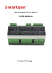
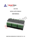
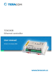
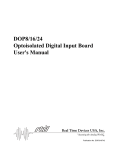
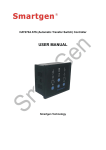
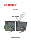
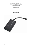
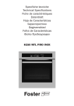
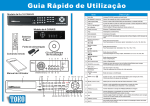
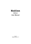
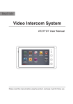
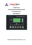
LA16 LED LAMP EXPANSION MODULE
USER MANUAL
ZHENGZHOU SMARTGEN TECHNOLOGY CO.,LTD
Chinese trademark
English trademark
SmartGen — make your generator smart
SmartGen Technology Co., Ltd.
No. 28 Jinsuo Road
Zhengzhou City
P. R. China
Tel: +86-371-67988888
+86-371-67981888
+86-371-67991553
+86-371-67992951
+86-371-67981000 (overseas)
Fax: 0086-371-67992952
Web:
http://www.smartgen.com.cn/
http://www.smartgen.cn/
Email: [email protected]
All rights reserved. No part of this publication may be reproduced in any material
form (including photocopying or storing in any medium by electronic means or
other) without the written permission of the copyright holder.
Smartgen Technology reserves the right to change the contents of this document
without prior notice.
If the colors of actual products are different from the manual, please take the
actual product as the standard.
Software Version
Date
2013-11-19
2015-03-25
Version
1.0
1.1
Content
Original release
Modify case dimension and cutout.
LA16 LED EXPANSION MODULE USER MANUAL
Contents
1 OVERVIEW ..................................................................................................................... 3
2 TECHNICAL PARAMETERS........................................................................................... 4
3 PANEL CONFIGURATION .............................................................................................. 6
3.1
3.2
3.3
FUNCTION DESCRIPTION ................................................................................................. 6
LED BUTTON DESCRIPTION ............................................................................................. 6
PARAMETER CONFIGURATION ........................................................................................ 7
4 LED SETTING................................................................................................................. 8
4.1
4.2
CUSTOM FOUNCTION...................................................................................................... 15
LED LABEL......................................................................................................................... 16
5 BACKPLATE ................................................................................................................. 17
6 INSTALLATION ............................................................................................................. 18
7 TROUBLESHOOTING .................................................................................................. 18
1 OVERVIEW
LED lamp expansion module is a LED display module which has 16 programmable lamp
LA16 LED EXPANSION MODULE
Version 1.1
2015-03-25
Page 3 of 18
LA16 LED EXPANSION MODULE USER MANUAL
and there are 3 kinds of color (red, green, yellow) can be chosen. The data collected by
LA16 are transmitted to the HMC9000 controller for processing via CANBUS port.
2 TECHNICAL PARAMETERS
Item
Working Voltage
LA16 LED EXPANSION MODULE
Content
DC18.0V~35.0V continuous power supply
Version 1.1
2015-03-25
Page 4 of 18
LA16 LED EXPANSION MODULE USER MANUAL
Item
Power Consumption
Case Dimension
Cutout
Working Conditions
Storage Conditions
Weight
LA16 LED EXPANSION MODULE
Content
<5W
180mm x 120mm x 37mm
163mm x 103mm
Temp.:(-25~+70)°C
Humidity:(20~93)%RH
Temp.:(-25~+70)°C
0.60kg
Version 1.1
2015-03-25
Page 5 of 18
LA16 LED EXPANSION MODULE USER MANUAL
3 PANEL CONFIGURATION
3.1
FUNCTION DESCRIPTION
Each lamp on the LA16 module can be set via HMC9000. The corresponding indicator will
flash when the setting is activated while turns into illuminating after press
button; in
addition, it is extinguished when the setting is deactivated.
3.2
LED BUTTON DESCRIPTION
is lamp test/dimmer button. All 5 kinds of lamp brightness levels will convert once for
every pushing. All lights on the LED panel will illuminate after long press this button and all
three kinds of lamp color will transfer once every 1 second.
is acknowledge button. Press this button can change the flashing lamp on the LED to
illuminating.
LA16 LED EXPANSION MODULE
Version 1.1
2015-03-25
Page 6 of 18
LA16 LED EXPANSION MODULE USER MANUAL
3.3
PARAMETER CONFIGURATION
The parameters of LA16 can be set via HMC9000. Pressing and holding
for more than
3s will enter into configuration interface in which users can set all kinds of parameters. More
details are as following:
Note: Pressing
can exit setting directly during setting.
Parameter Configuration List
1.
2.
3.
4.
5.
6.
7.
8.
9.
10.
11.
12.
13.
14.
15.
16.
17.
18.
19.
20.
21.
22.
23.
24.
25.
26.
27.
28.
29.
30.
31.
32.
Items
LED1 Set
LED 1 Color Set
LED 2 Set
LED2 Color Set
LED3 Set
LED3 Color Set
LED4 Set
LED4 Color Set
LED5 Set
LED5 Color Set
LED6 Set
LED6 Color Set
LED7 Set
LED7 Color Set
LED8 Set
LED8 Color Set
LED9 Set
LED9 Color Set
LED10 Set
LED10 Color Set
LED11 Set
LED11 Color Set
LED12 Set
LED12 Color Set
LED13 Set
LED13 Color Set
LED14 Set
LED14 Color Set
LED15 Set
LED15 Color Set
LED16 Set
LED16 Color Set
Range
(0-190)
(0-2)
(0-190)
(0-2)
(0-190)
(0-2)
(0-190)
(0-2)
(0-190)
(0-2)
(0-190)
(0-2)
(0-190)
(0-2)
(0-190)
(0-2)
(0-190)
(0-2)
(0-190)
(0-2)
(0-190)
(0-2)
(0-190)
(0-2)
(0-190)
(0-2)
(0-190)
(0-2)
(0-190)
(0-2)
(0-190)
(0-2)
LA16 LED EXPANSION MODULE
Default
0:Not used
0:Red
0:Not used
0:Red
0:Not used
0:Red
0:Not used
0:Red
0:Not used
0:Red
0:Not used
0:Red
0:Not used
0:Red
0:Not used
0:Red
0:Not used
0:Red
0:Not used
0:Red
0:Not used
0:Red
0:Not used
0:Red
0:Not used
0:Red
0:Not used
0:Red
0:Not used
0:Red
0:Not used
0:Red
Version 1.1
Remarks
LA16 Setting
LA16 Setting
LA16 Setting
LA16 Setting
LA16 Setting
LA16 Setting
LA16 Setting
LA16 Setting
LA16 Setting
LA16 Setting
LA16 Setting
LA16 Setting
LA16 Setting
LA16 Setting
LA16 Setting
LA16 Setting
LA16 Setting
LA16 Setting
LA16 Setting
LA16 Setting
LA16 Setting
LA16 Setting
LA16 Setting
LA16 Setting
LA16 Setting
LA16 Setting
LA16 Setting
LA16 Setting
LA16 Setting
LA16 Setting
LA16 Setting
LA16 Setting
2015-03-25
Page 7 of 18
LA16 LED EXPANSION MODULE USER MANUAL
4 LED SETTING
NO.
Items
00
Not used
01
User Configured
02
Air flap
03
Audible alarm
04
05
ECU power
ECU Stop
06
Crank Relay
07
Fuel Relay
08
09
ETS Hold
Reserved
10
Fuel Pump Control
11
Reserved
12
Louver Control
13
Loss of Speed
14
Heater Control
15
Pre-lubricate
16
Remote PC Output
17
Over Ride Output
18
Ready Go
19
Reserved
20
Idle Control
21
Pre-Supply Fuel
LA16 LED EXPANSION MODULE
Description
See 4.1
Action when over speed shutdown and emergence
stop. It also can close the air inflow to stop the
engine as soon as possible.
Action when warning, shutdown. Can be connected
annunciator externally. When “alarm mute”
configurable input port is active, it can remove the
alarm.
Used for ECU engine.
Used for ECU engine.
Action when genset is starting and disconnect when
crank success.
Action when genset is starting and disconnect when
stop is completed.
Action period: ETS hold delay.
It is controlled by fuel pump of level sensor’s limited
threshold.
Action when genset is starting and disconnect when
stop is completed.
After safety on delay, the controller active when the
engine speed is 0.
The controller disconnect when water temperature
lower than minimum setting threshold value or
higher than maximum setting threshold value.
The controller output when the engine is in standby
mode (user-defined output delay) if pre-lubrication
input is active.
The controller output when remote control is active
however disconnect when inactive.
The controller output when it is in override mode.
The controller output when it is in standby mode and
no alarms.
Action from “crank delay” to “start idle delay” and
from “stop idle delay” to “wait for stop delay”.
Action from “crank delay” to “safety on delay”.
Version 1.1
2015-03-25
Page 8 of 18
LA16 LED EXPANSION MODULE USER MANUAL
22
Raise Speed
23
Drop Speed
24
Crank Again
25
Power Change
26
High Speed
27
Common Alarm
28
29
30
31
32
33
34
35
36
37
38
39
40
41
42
43
44
45
46
47
48
Common Shutdown
Common Warn
Aux. Input 1 Active
Aux. Input 2 Active
Aux. Input 3 Active
Aux. Input 4 Active
Aux. Input 5 Active
Aux. Input 6 Active
Aux. Input 7 Active
Aux. Input 8 Active
Aux. Input 9 Active
Aux. Input 10 Active
Aux. Input 11 Active
Aux. Input 12 Active
Aux. Input 13 Active
Aux. Input 14 Active
Aux. Input 15 Active
Aux. Input 16 Active
Aux. Input 17 Active
Aux. Input 18 Active
Reserved
LA16 LED EXPANSION MODULE
Mechanical Governor: The controller output when
Raise Speed Output is active however disconnect
when inactive.
ECU Governor: Users can govern speed via this
port. User-defined rate.
Mechanical Governor: The controller output when
Speed Droop Output is active however disconnect
when inactive.
ECU Governor: Users can govern speed via this
port. User-defined rate.
The relay outputs when controller start failed and
start secondary if the configuration is active
(expansion relay is needed).
Action when battery 1 voltage has fallen below the
transfer value. Deactivate when battery 1 voltage
has exceed the transfer value.
The controller act from warming up delay to cooling
down delay. (contrary to idle speed output)
Action when genset common warning, common
shutdown alarm.
Action when common shutdown alarm.
Action when common warning alarm.
Action when input port 1 is active.
Action when input port 2 is active.
Action when input port 3 is active.
Action when input port 4 is active.
Action when input port 5 is active.
Action when input port 6 is active.
Action when input port 7 is active.
Action when input port 8 is active.
Action when input port 9 is active.
Action when input port 10 is active.
Action when input port 11 is active.
Action when input port 12 is active.
Action when input port 13 is active.
Action when input port 14 is active.
Action when input port 15 is active.
Action when input port 16 is active.
Action when input port 17 is active.
Action when input port 18 is active.
Version 1.1
2015-03-25
Page 9 of 18
LA16 LED EXPANSION MODULE USER MANUAL
49
Crank Success
50
Normal Running
51
52
53
54
55
Remote Mode
Local Mode
Waiting For Load
Reserved
Reserved
56
Pulse Stop
57
58
59
60
61
62
63
64
65
66
67
68
69
70
71
72
73
74
75
The gen-set start when the engine speed reaches
requirements.
The gen-set is normal running when the speed
reaches rated requirements.
The controller output in remote control mode.
The controller output in local mode.
The controller output in Waiting For Load delay.
Action during stop delay while deactivate after the
delay.
Action when the controller detects communication
AIN16 Com Fail
failure with AIN16. (3s overtime)
Action when the controller detects communication
DIN16 Com Fail
failure with DIN16. (3s overtime)
Action when the controller detects communication
RPU560 Com Fail
failure with RPU560 safeguard module. (1s
overtime)
Action when the controller detects communication
DOUT16 Com Fail
failure with DOUT16. (3s overtime)
Reserved
Reserved
Action when the controller detects communication
LA16 Com Fail
failure with LA16. (3s overtime)
Action when the controller detects no ECU
ECU Com Fail
connection after ECU powered on.
Action when the controller receives warning alarm
ECU Warn
from ECU.
Action when the controller receives shutdown alarm
ECU Shutdown
from ECU.
Action when the controller detects that the battery 1
Bat 1 Under Volt
voltage has fallen below the set value.
Action when the controller detects that the battery 2
Bat 2 Under Volt
voltage has fallen below the set value.
Under Speed Warn
Action when under speed warning.
Under Speed Shutdown Action when under speed shutdown alarm.
Over Speed Warn
Action when over speed warning.
Over Speed Shutdown Action when over speed shutdown alarm
Emergency Stop
Action when emergency stop alarm.
Charge Alt Fail
Action when charge failure warning.
Reserved
Failed To Start
Action when failed stop alarm.
LA16 LED EXPANSION MODULE
18
Version 1.1
2015-03-25
Page 10 of
LA16 LED EXPANSION MODULE USER MANUAL
76
77
78
79
80
81
82
83
84
85
86
87
88
89
90
91
92
93
94
95
96
97
98
99
100
101
102
103
104
105
106
107
108
109
Reserved
Reserved
Sensor 1 Open
Sensor 1 Warn
Sensor 1 Shutdown
Sensor 2 Open
Sensor 2 Warn
Sensor 2 Shutdown
Sensor 3 Open
Sensor 3 Warn
Sensor 3 Shutdown
Sensor 4 Open
Sensor 4 Warn
Sensor 4 Shutdown
Sensor 5 Open
Sensor 5 Warn
Sensor 5 Shutdown
Sensor 6 Open
Sensor 6 Warn
Sensor 6 Shutdown
Sensor 7 Open
Sensor 7 Warn
Sensor 7 Shutdown
Sensor 8 Open
Sensor 8 Warn
Sensor 8 Shutdown
AIN16-1
Sensor
1
Open (expansion 1)
AIN16-1 Sensor 1 Warn
(expansion 1)
AIN16-1 Sensor 1 Stop
(expansion 1)
AIN16-1
Sensor
2
Open (expansion 1)
AIN16-1 Sensor 2 Warn
(expansion 1)
AIN16-1 Sensor 2 Stop
(expansion 1)
AIN16-1
Sensor
3
Open (expansion 1)
AIN16-1 Sensor 3 Warn
LA16 LED EXPANSION MODULE
18
Action when sensor 1 is open circuit.
Action when sensor 1 warning alarm.
Action when sensor 1 shutdown alarm.
Action when sensor 2 is open circuit.
Action when sensor 2 warning alarm.
Action when sensor 2 shutdown alarm.
Action when sensor 3 is open circuit.
Action when sensor 3 warning alarm.
Action when sensor 3 shutdown alarm.
Action when sensor 4 is open circuit.
Action when sensor 4 warning alarm.
Action when sensor 4 shutdown alarm.
Action when sensor 5 is open circuit.
Action when sensor 5 warning alarm.
Action when sensor 5 shutdown alarm.
Action when sensor 6 is open circuit.
Action when sensor 6 warning alarm.
Action when sensor 6 shutdown alarm.
Action when sensor 7 is open circuit.
Action when sensor 7 warning alarm.
Action when sensor 7 shutdown alarm.
Action when sensor 8 is open circuit.
Action when sensor 8 warning alarm.
Action when sensor 8 shutdown alarm.
Action when sensor 1 opening circuit. (expansion 1)
Action when sensor 1 warning alarm. (expansion 1)
Action when sensor 1 shutdown alarm. (expansion
1)
Action when sensor 2 opening circuit. (expansion 1)
Action when sensor 2 warning alarm. (expansion 1)
Action when sensor 2 shutdown alarm. (expansion
1)
Action when sensor 3 opening circuit. (expansion 1)
Action when sensor 3 warning alarm. (expansion 1)
Version 1.1
2015-03-25
Page 11 of
LA16 LED EXPANSION MODULE USER MANUAL
110
111
112
113
114
115
116
117
118
119
120
121
122
123
124
125
126
127
128
129
(expansion 1)
AIN16-1 Sensor 3 Stop
(expansion 1)
AIN16-1
Sensor
4
Open (expansion 1)
AIN16-1 Sensor 4 Warn
(expansion 1)
AIN16-1 Sensor 4 Stop
(expansion 1)
AIN16-1
Sensor
5
Open (expansion 1)
AIN16-1 Sensor 5 Warn
(expansion 1)
AIN16-1 Sensor 5 Stop
(expansion 1)
AIN16-1
Sensor
6
Open (expansion 1)
Action when sensor 3 shutdown alarm. (expansion
1)
Action when sensor 4 opening circuit. (expansion 1)
Action when sensor 4 warning alarm. (expansion 1)
Action when sensor 4 shutdown alarm. (expansion
1)
Action when sensor 5 opening circuit. (expansion 1)
Action when sensor 5 warning alarm. (expansion 1)
Action when sensor 5 shutdown alarm. (expansion
1)
Action when sensor 6 opening circuit. (expansion 1)
AIN16-1 Sensor 6 Warn
Action when sensor 6 warning alarm. (expansion 1)
(expansion 1)
AIN16-1 Sensor 6 Stop
(expansion 1)
AIN16-1
Sensor
7
Open (expansion 1)
AIN16-1 Sensor 7 Warn
(expansion 1)
AIN16-1 Sensor 7 Stop
(expansion 1)
AIN16-1
Sensor
8
Open (expansion 1)
AIN16-1 Sensor 8 Warn
(expansion 1)
AIN16-1 Sensor 8 Stop
(expansion 1)
AIN16-1
Sensor
9
Open (expansion 1)
AIN16-1 Sensor 9 Warn
(expansion 1)
AIN16-1 Sensor 9 Stop
(expansion 1)
AIN16-1 Sensor 10
LA16 LED EXPANSION MODULE
18
Action when sensor 6 shutdown alarm. (expansion
1)
Action when sensor 7 opening circuit. (expansion 1)
Action when sensor 7 warning alarm. (expansion 1)
Action when sensor 7 shutdown alarm. (expansion
1)
Action when sensor 8 opening circuit. (expansion 1)
Action when sensor 8 warning alarm. (expansion 1)
Action when sensor 8 shutdown alarm. (expansion
1)
Action when sensor 9 opening circuit. (expansion 1)
Action when sensor 9 warning alarm. (expansion 1)
Action when sensor 9 shutdown alarm. (expansion
1)
Action when sensor 10 opening circuit. (expansion
Version 1.1
2015-03-25
Page 12 of
LA16 LED EXPANSION MODULE USER MANUAL
130
131
132
133
134
135
136
137
138
139
140
141
142
143
144
145
146
147
148
149
Open (expansion 1)
AIN16-1 Sensor 10
Warn (expansion 1)
AIN16-1 Sensor 10
Stop (expansion 1)
AIN16-1 Sensor 11
Open (expansion 1)
AIN16-1 Sensor 11
Warn (expansion 1)
AIN16-1 Sensor 11
Stop (expansion 1)
AIN16-1 Sensor 12
Open (expansion 1)
AIN16-1 Sensor 12
Warn (expansion 1)
AIN16-1 Sensor12 Stop
(expansion 1)
AIN16-1 Sensor 13
Open (expansion 1)
AIN16-1 Sensor 13
Warn (expansion 1)
AIN16-1 Sensor 13
Stop (expansion 1)
AIN16-1 Sensor 14
Open (expansion 1)
AIN16-1 Sensor 14
Warn (expansion 1)
AIN16-1 Sensor 14
Stop (expansion 1)
AIN16-1 Sensor 15
Open (expansion 1)
AIN16-1 Sensor 15
Warn (expansion 1)
AIN16-1 Sensor 15
Stop (expansion 1)
AIN16-1 Sensor 16
Open (expansion 1)
AIN16-1 Sensor 16
Warn (expansion 1)
AIN16-1 Sensor 16
Stop (expansion 1)
LA16 LED EXPANSION MODULE
18
1)
Action when sensor 10 warning alarm. (expansion 1)
Action when sensor 10 shutdown alarm. (expansion
1)
Action when sensor 11 opening circuit. (expansion
1)
Action when sensor 11 warning alarm. (expansion 1)
Action when sensor 11 shutdown alarm. (expansion
1)
Action when sensor 12 opening circuit. (expansion
1)
Action when sensor 12 warning alarm. (expansion 1)
Action when sensor 12 shutdown alarm. (expansion
1)
Action when sensor 13 opening circuit. (expansion
1)
Action when sensor 13 warning alarm. (expansion 1)
Action when sensor 13 shutdown alarm. (expansion
1)
Action when sensor 14 opening circuit. (expansion
1)
Action when sensor 14 warning alarm. (expansion 1)
Action when sensor 14 shutdown alarm. (expansion
1)
Action when sensor 15 opening circuit. (expansion
1)
Action when sensor 15 warning alarm. (expansion 1)
Action when sensor 15 shutdown alarm. (expansion
1)
Action when sensor 16 opening circuit. (expansion
1)
Action when sensor 16 warning alarm. (expansion 1)
Action when sensor 16 shutdown alarm. (expansion
1)
Version 1.1
2015-03-25
Page 13 of
LA16 LED EXPANSION MODULE USER MANUAL
DIN16-1 Input 1 Active
(expansion 1)
DIN16-1 Input 2 Active
151
(expansion 1)
DIN16-1 Input 3 Active
152
(expansion 1)
DIN16-1 Input 4 Active
153
(expansion 1)
DIN16-1 Input 5 Active
154
(expansion 1)
DIN16-1 Input 6 Active
155
(expansion 1)
DIN16-1 Input 7 Active
156
(expansion 1)
DIN16-1 Input 8 Active
157
(expansion 1)
DIN16-1 Input 9 Active
158
(expansion 1)
DIN16-1 Input 10 Active
159
(expansion 1)
DIN16-1 Input 11 Active
160
(expansion 1)
DIN16-1 Input 12 Active
161
(expansion 1)
DIN16-1 Input 13 Active
162
(expansion 1)
DIN16-1 Input 14 Active
163
(expansion 1)
DIN16-1 Input 15 Active
164
(expansion 1)
DIN16-1 Input 16 Active
165
(expansion 1)
166~190 Reserved
150
LA16 LED EXPANSION MODULE
18
Action when input port 1 is active (expansion 1)
Action when input port 2 is active (expansion 1)
Action when input port 3 is active (expansion 1)
Action when input port 4 is active (expansion 1)
Action when input port 5 is active (expansion 1)
Action when input port 6 is active (expansion 1)
Action when input port 7 is active (expansion 1)
Action when input port 8 is active (expansion 1)
Action when input port 9 is active (expansion 1)
Action when input port 10 is active (expansion 1)
Action when input port 11 is active (expansion 1)
Action when input port 12 is active (expansion 1)
Action when input port 13 is active (expansion 1)
Action when input port 14 is active (expansion 1)
Action when input port 15 is active (expansion 1)
Action when input port 16 is active (expansion 1)
Version 1.1
2015-03-25
Page 14 of
LA16 LED EXPANSION MODULE USER MANUAL
4.1 CUSTOM FOUNCTION
NO.
Items
1
Active period
2
3
Output delay
Output time
LA16 LED EXPANSION MODULE
18
Contents
Bit0: Not used
Bit1: At rest
Bit2: Preheating
Bit3: Fuel on
Bit4: Cranking
Bit5: Crank rest
Bit6: Safety on
Bit7: Start idle
Bit8: Warming up
Bit9: Wait for load
Bit10: Normal running
Bit11: Cooling down
Bit12: Stop idle delay
Bit13: ETS hold
Bit14: Wait For Stop
Bit15: Fail to stop
(0-100.0)s
(0-3600)s
Version 1.1
Remarks
2015-03-25
Page 15 of
LA16 LED EXPANSION MODULE USER MANUAL
4.2 LED LABEL
1. LED name windows can be set by users. The insertion way is as following:
2. Label information can be set by users using PC software. The procedures are listed as
following: Edit Configuration→ Extension Module→LA16 Module. The set information can be
printed by pressing “Label Print” button and the printed label can be placed in the name
window in one-to-one correspondence.
LA16 LED EXPANSION MODULE
18
Version 1.1
2015-03-25
Page 16 of
LA16 LED EXPANSION MODULE USER MANUAL
5 BACKPLATE
Panel diagram
Description of terminal connection:
No.
1.
2.
3.
4.
5.
6.
Function
DC input BDC input B+
SCR
(CANBUS)
CAN(H)
(CANBUS)
CAN(L)
(CANBUS)
120Ω
Cable Size
2.5mm2
2.5mm2
0.5mm2
SWITCH
LA16 LED EXPANSION MODULE
18
Description
DC power supply negative input.
DC power supply positive input.
A CANBUS port which communicate with
HMC9000
controller.
Impedance-120Ω
shielding wire with its one end grounded is
recommended. There is 120Ω terminal
resistance inside already; if needed, make
terminal 5, 6 short circuits.
Address selection :It is module 1 when the
switch 1 is connected to terminal 12 while
module 2 when connect to ON terminal.
Baud rate selection: It is 250kbps when the
switch 2 is connected to terminal 12 while
125kbps when connect to ON terminal.
Version 1.1
2015-03-25
Page 17 of
LA16 LED EXPANSION MODULE USER MANUAL
6 INSTALLATION
Case dimensions:
7 TROUBLESHOOTING
PROBLEM
Controller no response
power.
POSSIBLE SOLUTION
with
CANBUS communication failure
LA16 LED EXPANSION MODULE
18
Check controller connection wirings.
Check if CANBUS wires are connected in the
opposite way;
Version 1.1
2015-03-25
Page 18 of