1
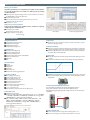
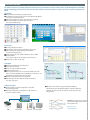
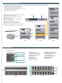
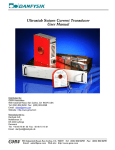
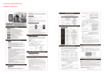
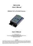
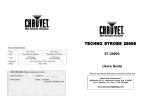
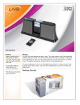
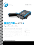
Regenerative Battery Pack
Test System
Model 17020
Features:
■ Regenerative battery energy discharge
●
Energy saving
●
Environment protection
●
Low heat generate
■ Channels paralleled for higher currents
■ Charge / discharge mode (CC, CV, CP)
● Constant current
● Constant voltage
● Constant power
■ Driving cycle simulation
■ High precision measurement accuracy
■ Fast current conversion
■ Smooth current without over shoot
■ Testing data analysis function
REGENERATIVE BATTERY PACK TEST SYSTEM
MODEL 17020
Chroma's 17020 is a high precision system
specifically designed for secondar y batter y
modules and pack tests. Highly accurate sources
and measurements ensures that the test quality
is suitable to perform repetitive and reliable
tests this is crucial for battery modules / packs,
for both incoming and outgoing inspections as
well as capacity, performance, production and
qualification testing.
Chroma's 17020 system architec ture offers
regenerative discharge designed to recycle the
electric energy sourced by the battery module
e i t h e r b a c k to t h e c h a n n e l s i n t h e s ys te m
performing a charging function or to the utility
mains in the most energy efficient manner. This
feature saves electricity, reduces the facilities
thermal foot print and provides a green solution.
Chroma's 17020 system is equipped with multiple
independent channels to support dedicated charge
/ discharge tests on multiple battery modules /
packs, each with discrete test characteristics. The
channels can easily be paralleled to support higher
current requirements. This feature provides the
ultimate flexibility between high channel count
and high current testing.
The 17020 advanced hardware design can create
seamless transitions between maximum charge
and maximum discharge (or maximum discharge
a n d m a x i m u m c h a r g e) w i t h a r a p i d 50 m s
conversion. This feature allows for charge/discharge
modes for simulating real world scenarios.
Chroma's 17020 system has flexible programming
functions and may be operated with Chroma's
powerful Battery Pro software. Battery Pro utilizes
the system to create cycling tests from basic charge
or discharge to complex drive cycle testing for each
channel or channel groups. A thermal chamber
control can be integrated into a profile and
triggered by time or test results yielding a dynamic
profile. Battery Pro's features allows for quick and
intuitive test development to eliminate the need
of tedious scripting or programming by a software
engineer.
There are multiple safety features including Battery
Polarity Check, Over Voltage Protection, Over
Current Protection check and Over Temperature
Protection to ensure protected charge / discharge
testing. In the unlikely event of power or computer
communication loss, the data is securely stored in
the system, on a non-volatile memory, protecting
against potential data loss and allowing for
continuous flow after restart.
Ethernet
■ Data recovery protection (after power failure)
■ Independent protection of multi-channel
■ BMS data recording
■ Thermal chamber control integration
APPLICATIONS
Battery Pack
■ EV battery module
■ Electric scooter/ bike
■ UPS
■ Electric gardening tools
■ Energy storage battery
■ Power tools
■ Car battery
■ Lead-acid battery
Application
■ Drive cycle simulator
■ Learning test for manufactory
■ Life cycle test
■ Balance control test
■ DCIR test
■ Capacity test
■ Performance test
■ Reliability test
■ Over charge/dischargetest
■ Thermal test
REGENERATIVE ENERGY
■ Regenerative battery energy discharge
-Direct recycle back to the battery unber charging
-Regenerate to grid
■ Low heat output
■ Reduce air-conditioner power consumption
■ The THD of 17020 system is under 5% at rated power
■ The PF is over 0.9 at rated power
■ Return to factory directly
Efficiency 85%
PARALLEL FUNCTIONS
Parallel function
1.Set dip switches
2.Connect communication cables
Multi-channels
■ Supports various capacity batteries by paralleling
■ The system supports different capacity batteries from a base
system configuration
■ Battery companies have various capacity configurations. Some
customers may purchase a high power system to test all capacity
battery packs. The downside is that measurements accuracy are not
3.Connect UUTs
4.Software automatic detection
sufficient for small-capacity battery packs. Using Chroma's systems,
customers test under individual channels or parallel to test higher
capacity battery packs
10AH×16
20AH×8
DRIVING CYCLE SIMULATION
Driving cycle simulation
The battery pack always is used at quick and un-regular current condition.
The system simulates the real condition on battery pack by working
condition simulator.
■ Import dynamic charge/discharge power or current waveforms to simulate
the DRIVE CYCLE or the actual application.
■ Support Excel (xls) format
■ There are 720,000 points of driving profile memory to save the
waveform profile in each channel.
■ Minimum Δt:10ms
High accuracy capacity calculation
Voltage/current sampling rate of 50kHz used for calculations of capacity
ratings in dynamic waveform mode. ■ V/I sampling rate : 50KHz
Minimum data acquisition: 10ms
■ Integrate calculus : For I : Capacity
For V x I : Energy
Sampling rate
Catch the V/I pre 20us
Sampling rate
Feedback the V/I pre 10ms
Other Cycler
Double Integrating Method
17020 FUNCTIONS
Independent Channels
■ Independent channel operation
■ Independent testing data
■ Independent protection
■ Independent testing process
Operating mode
■ Constant current (CC) mode
■ Constant voltage (CV) mode
■ Constant power (CP) mode
■ Constant voltage-limit current mode (CC-CV)
■ Waveform current mode
■ DCIR mode
■ Rest
Cut-off conditions
■ Time (s)
■ Capacity (Ah)
■ Voltage (V)
■ Current (A)
■ Temperature (℃)
■ Channel data in data logger (Option)
Protection conditions
■ Over voltage protection (V)
■ Under voltage protection (V)
■ Over current protection (A)
■ Over temperature protection (℃)
■ Over capacity protection (Ah)
■ Wire loss protection (ΔV)
■ Channel data in data logger (Option)
■ -ΔV /+ΔV protection (V)
■ +ΔI /-ΔI protection (A)
■ Delta Protection: Protect internal short of battery cell
Testing data record
■ Independent testing data
■ Detail report: STEP/TEST TIME/TEST TIME ID/Cycle/Loop/STEP MODE
/STEP TIME/VOLTAGE(V)/CURRENT(A)/CAPACITY (Ah)/Energy (Wh)/
TEMPERATURE (℃)/Data Logger Channel (Option)
■ STEP/STEP NO/LOOP/CYCLE/STATUS/STEP START TIME/ STEP
MODE /CUT OFF VOLTAGE(V) /CUT OFF CURRENT(A)/CUT OFF
CAPACITY(Ah) /DCIR(mOhm)/Energy (Wh)/TEMPERATURE (℃)/
Data Logger Channel (Option)
Compact Size
■ The dimensions of a regenerative system is smaller compared to a system
that has to dissipate energy.
Continuous transition
■ Continuous charge and discharge transition: No time delay to transit from
charge to discharge. The user can verify the battery pack for a design limit.
■ Continuous CC-CV transition: No overshoot current or voltage to damage
the battery when transiting CC-CV.
Response time
■ The trip time between maximum charge and maximum discharge current
is 50ms.
■ Smooth current without overshoot for avoiding to damage the battery.
Temperature Measurement
■ Temperature measured for each channel within the range of 0~90℃±2℃.
■ 4 sets of measurements (Max) per channel to measure the battery surface
temperature.
Thermal sensor
Test for battery pack with split connections
For some battery pack design, the charge and discharge ports are
split to two connectors. Users can set 17020 software to select
Charge/discharge going through with a single connector or two connectors
separately.
Discharge
Charge
Data Recovery Function
■ 60 min of temporary data storage when sampling time is 1 sec.
■ Save the test settings to resume after power failure is recovered.
SOFTWARE FUNCTION
The 17020 Test system is specifically designed to meet the various requirements for testing secondary battery packs with high safety and stability.
Charge and discharge protection aborts tests when abnormal conditions are detected. Data loss, storage and recovery are protected against power
failure.
User friendly
■ Real-time multi channel battery pack status browse
■ Icon Manager: Test status of each channel is managed through different
icons, easy to read and understand.
■ Authority management: It sets the user's authority for operation.
■ Fault record tracking: It records the abnormal state of
each channel independently.
Recipe editor
■ 255 charge/discharge conditions
■ Sets dual layer loops (cycle & loop) with 9999 loops per layer
■ Able to edit dynamic charge/discharge waveform with
10ms current switching speed
■ Testing Step: CV/CC/CP/CC-CV/Waveform current/DCIR)
■ Cut-off conditions
(time, current, capacity, cut-off voltage, cut-off current, etc.)
■ Next Step: Next/End/Jump/Rest
Cycle Life Testing
Testing Data
Capacity Measurement
■ Generate the detailed report and step report
■ Customized report format
■ Exports test reports in PDF, CSV and XLS
■ Graphical report function
■ Report analysis Function: Users can create customized reports such
as life-cycle report, Q (AH)-V(V) report, V(V)/I(A)/T( ℃)-time report…etc
through the user-defined X and Y axis parameters.
■ Real-time browsing test reports of each channel
■ Diversified reports & charts: Real-time report, Cut-off report,
X-Y scatter chart report
Software integration
■ Thermal chamber: Synchronize temperature control with
charge/discharge profile.
■ Data logger: Temperature or voltage data record. Cut-off and
protection conditions setting.
■ BMS data record: Software setting to read data from BMS by
Data Communication unit A692000/A692001. It supports SmBus and
CAN bus. The data can be set the conditions for cut-off or protection
during testing.
CHROMA Data logger 51101 provides
synchronized sampling with constant
data acquisition rate.
BMS
17020 system
Chamber
Data logger
Minimun: 200 ms
Interface : Ethernet
FLEXIBLE SYSTEM CONFIGURATION
17020 Regenerative Battery Pack Test System can be configured to specified requirements and expandable to 60 channels.
1. Battery Charge/Discharge Controller : Model 69200-1
2. DC/AC Bi-directional Converter : Model A691101
3. Regenerative Charge/Discharge Tester : Model 69200 series
4. Data logger (option): Model 51101-64
5. BMS data communication unit
■ Support B, E, J, K, N, R, S, and T type thermal couples with
ITS-90 defined temperature range
■ Individual channel cold junction compensation
with <±0.3˚C accuracy
■ Temperature resolution up to 0.01˚C,error down to
(0.01% of reading+0.3˚C)
■ Voltage full range ±10VDC; resolution 10uV;
error down to 0.015% of reading+100uV
■ No matter how many channels are active, the data rate
can be as fast as 5 samples per second per channel.
Terminals
V-sense
The driving cable can connect the front panel or rear outlet,
users can choose their own.
1
5
2
4
3
8 CH
16 CH
48CH
692XX INTERFACE
Model 69206-60-8
1
2
3
4
5
1. Channel No
2. Charge Status Indicator
3. Discharge Status Indicator
4. UUT Connection Indicator
5. Parallel Indicator
6. Failure Indicator
7. Power Switch
8. Channel DIP Switch
9. Parallel Connector
10. Temperature Meas. Terminal
11. Voltage Meas. Terminal
12. Charge/ Discharge Output/
Input Connector
13. Charge Output Connector
14. Controller Connector
15. DC BUS Terminal
16. AC Input
6
8
14
9
10
7
15
11
12
16
13
Front site
Back site
SPECIFICATIONS
Model
Channel
Charge /
Discharge
Mode
Measurement
Others
Temperature
Coefficient
Voltage Range
Maximum Current
Max Power
CC mode accuracy
Current Resolution
CV mode accuracy
Voltage Resolution
CP mode accuracy
Power Resolution
Voltage range
Voltage accuracy
Voltage resolution
Current range
Current accuracy
Current resolution
Power range
Power accuracy
Power resolution
Temperature range
Temperature accuracy
Temperature resolution
Protection
Efficiency (Typical)
69206-60-8
8
0-60Vdc
13A
600W
69212-20-4
4
0V-20Vdc
65A
1250W
1mA
5mA
1mV
0.5mV
0.1W
0~60V
0.1W
0~20V
1mV
4.8A/13A
0.5mV
24A/65A
1mA
0~600W
5mA
0~1250W
0.1W
0.1W
69212-60-4
69225-60-4
4
4
0V-60Vdc
0V-60Vdc
62.5A
62.5A
1250W
2500W
0.1% stg. +0.05% F.S.
5mA
5mA
0.1% stg. +0.05% F.S.
2mV
2mV
0.2% stg. +0.1% F.S.
0.3W
0.3W
0~60V
0~60V
0.02% rdg.+0.02% F.S.
2mV
2mV
24A/62.5A
24A/62.5A
0.05% rdg+0.05% rng
5mA
5mA
0~1250W
0~2500W
0.12% rdg. + 0.07% rng.
0.3W
0.3W
0-90℃
±2℃
0.1℃
UVP, OCP, OPP, OTP, FAN
85~90%
Voltage/Current
Weight
69225-200-4
4
0V-200Vdc
30A
2500W
5mA
5mA
3mV
5mV
0.5W
0~100V
0.5W
0~200V
3mV
20A/50A
5mV
12A/30A
3mA
0~2500W
3mA
0~2500W
0.3W
0.3W
50ppm/ ℃
177 x 428 x
600.7mm / 6.9 x
16.9 x 23.6inch
38.6kg / 85lbs
Dimension(H x W x D)
69225-100-4
4
0V-100Vdc
50A
2500W
177 x 428 x 700mm 177 x 428 x 700mm 177 x 428 x 700mm 177 x 428 x 700mm 177 x 428 x 700mm
6.9 x 16.9 x 27.5inch 6.9 x 16.9 x 27.5inch 6.9 x 16.9 x 27.5inch 6.9 x 16.9 x 27.5inch 6.9 x 16.9 x 27.5inch
37kg / 82lbs
37kg / 82lbs
37kg / 82lbs
37kg / 82lbs
37kg / 82lbs
Model A691101 DC/AC Bi-direction Converter
Regenerative Bi-Direction Power
Voltage Range
1Ø 200~240V ±5%, 47~63Hz
Current Range
45A
Current THD/ Power Factor
< 5% / > 0.9 at rated power
Protection
UVP, OCP, OPP, OTP, FAN, Short
Dimension (H x W x D)
83.94 x 425.8 x 696 mm / 3.3 x 16.8 x 27.4 inch
Weight
25kg / 55.2lbs
Model 69200-1 Battery Charge/Discharge Controller
Data Acquisition Rate to PC
minimum 40ms@4CH independent, 10ms@4CH parallel, 600ms@60CH independent, 100ms@60CH parallel
PC Interface
Ethernet
Dimension (H x W x D)
88.1 x 428 x 420mm / 3.5 x 16.9 x 16.5inch
Weight
9.4kg / 21lbs
General Specifications
Operation
0℃ ~ 40℃
Temperature
Storage
-40℃ ~ 85℃
Safety & EMC
CE
Input AC Power Voltage range
1Ø 100~240V ±10%, 47~63Hz
* All specifications are subject to change without notice. Please visit our website for the most up to date specifications.
Note*1: The output range of voltage is referred by the cabling. The connection between the device and battery is 3 meters long as standard accessory.
Note*2: 20us sampling rate for calculating battery capacity and energy.
Note*3: The maximum discharge current will derate at low voltage range between 2V to 0V, please refer the user's manual for the detail V-I curve.
ORDERING INFORMATION
17020: 600W/60V/13A per channel, 8-56CH
17020: 1250W/20V/65A per channel, 4-60CH
17020: 1250W/60V/62.5A per channel, 4-60CH
17020: 2500W/60V/62.5A per channel, 4-60CH
17020: 2500W/100V/50A per channel, 4-60CH
A170201: IPC for battery pack test system
A692000: Data communication unit (4CH)
A692001: Data communication unit (8CH)
A692003: Thermal sensor and extension cable
51101-64: Data logger, max 64 channels
Developed and Manufactured by :
CHROMA ATE INC.
致茂電子股份有限公司
HEADQUARTERS
66 Huaya 1st Road, Guishan,
Taoyuan 33383,
Taiwan
Tel: +886-3-327-9999
Fax: +886-3-327-8898
http://www.chromaate.com
E-mail:[email protected]
CHINA
CHROMA ELECTRONICS
(SHENZHEN) CO., LTD.
8F, No.4, Nanyou Tian An
Industrial Estate, Shenzhen,
China PC: 518052
Tel: +86-755-2664-4598
Fax: +86-755-2641-9620
JAPAN
CHROMA JAPAN CORP.
472 Nippa-cho, Kouhoku-ku,
Yokohama-shi, Kanagawa,
223-0057 Japan
Tel: +81-045-542-1118
Fax: +81-045-542-1080
http://www.chroma.co.jp
E-mail:[email protected]
U.S.A.
CHROMA ATE INC. (U.S.A.)
7 Chrysler Irvine, CA 92618
Tel: +1-949-421-0355
Fax: +1-949-421-0353
Toll Free: +1-800-478-2026
http://www.chromaus.com
E-mail: [email protected]
CHROMA SYSTEMS
SOLUTIONS, INC.
19772 Pauling, Foothill Ranch,
CA 92610
Tel: +1-949-600-6400
Fax: +1-949-600-6401
http://www.chromausa.com
E-mail: [email protected]
Distributed by:
EUROPE
CHROMA ATE EUROPE B.V.
Morsestraat 32, 6716 AH Ede,
The Netherlands
Tel: +31-318-648282
Fax: +31-318-648288
http://www.chromaeu.com
E-mail: [email protected]
Worldwide Distribution and Service Network
17020-E-201501-PDF