1
Create circuit diagram
87
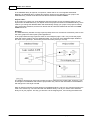
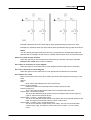
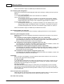
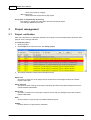
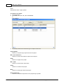
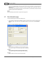
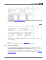
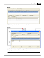
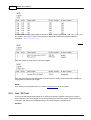
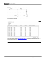
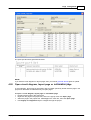
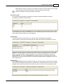
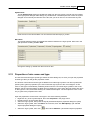
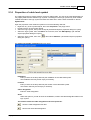
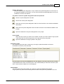
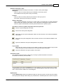
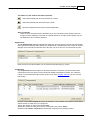
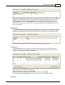
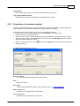
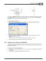
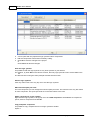
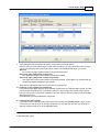
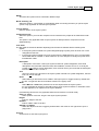
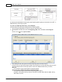
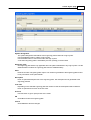
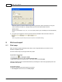
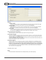
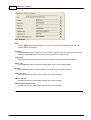
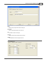
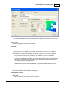
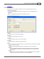
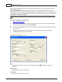
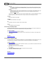
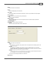
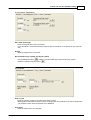
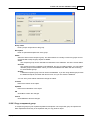
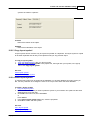
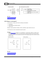
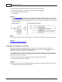
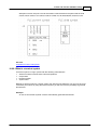
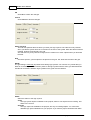
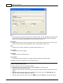
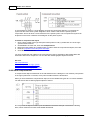
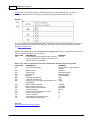
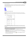
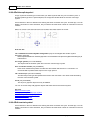
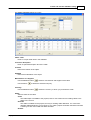
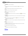
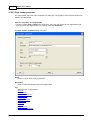
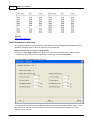
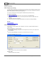
In the above example the logic symbol has one child symbol. The information in the column Child
symbol is from the designer of the logic symbol and is normally a representative text of the child
symbol. If the child symbol is already used then a cross reference text will show in the column
Cross reference. The column Cross points and all other columns are connection points for the
child symbol. The cross point names are in most cases pre-defined from the database, but you are
free to change them.
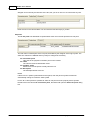
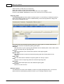
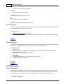
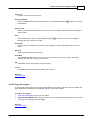
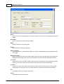
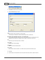
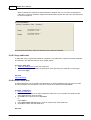
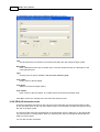
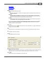
Symbol texts
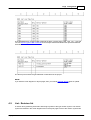
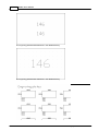
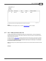
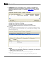
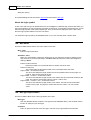
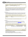
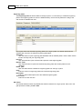
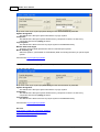
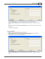
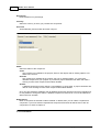
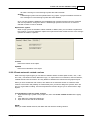
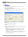
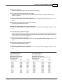
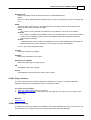
The tab Symbol texts shows all variable text fields from the logic symbol. This tab may be invisible
if the logic symbol designer didn't design any variable texts. The description text is from the symbol
designer and is normally the intention of the text, but you as an user can of course write any text.
Enter the text in the column Text. You can leave the text field empty if you like.
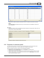
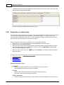
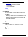
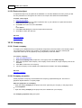
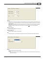
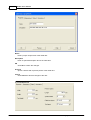
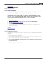
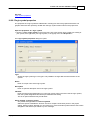
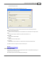
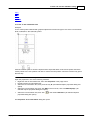
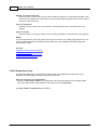
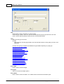
Components
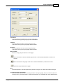
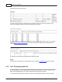
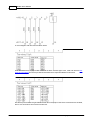
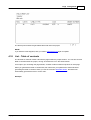
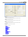
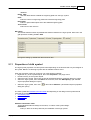
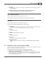
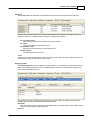
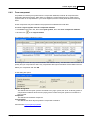
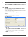
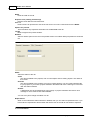
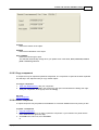
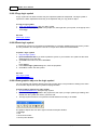
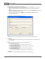
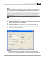
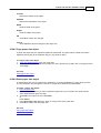
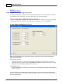
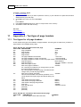
The components tab will be visible for all logic symbols. On this tab you will be able to add
components to the logic symbol. Each component added will be listed in the list. The maximum
number of components per auxiliary symbol is 20.
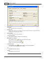
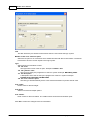
Click the button Add component to open the database of the available components. Use the Elwin
search function to easily find your component.
Specify the number of units in the column Units.
Specify the number of spare parts for each component in the column Spare.
Click the button Delete component to remove the component from the logic symbol.
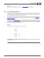
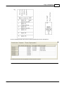
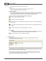
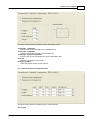
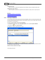
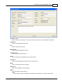
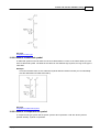
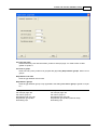
DIP switch
Copyright © 2006-2015 3xM Software