1
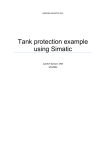
Your Universal Room Controller
Figure 3 and Table 3 define the RC-8RK and RC-8RKL lower rear panel:
Figure 3: RC-8RK and the RC-8RKL Lower Rear Panel
Table 3: RC-8RK and the RC-8RKL Lower Rear Panel Features
#
Feature
1 +12VDC IN PIN
2 GND PIN
3 IR OUT1 PIN
GND PIN
IR OUT2 PIN
4 RS-232 Terminal Block
Connector (1 and 2)
5 RS-485 Terminal Block
Connector
6 RELAY1
7 RELAY2
Function
Connects (+) to the connector for powering the unit
Connects (-) to the Ground
Connect to an IR emitter cable
Connect to the RS-232 connector on the A/V equipment or a PC or other
Serial Controller
Connect to the RS-485 detachable terminal block on a switcher or PC
Connect each relay to a room item (such as lighting, screen settings,
blinds, and so on)
1
Figure 4 and Table 4 define the RC-8RK and RC-8RKL upper rear panel:
1 See the examples in Figure 6
5