1
Model
H-4501
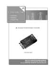
SDI-12 Fiberoptic Media Converter
Owner's Manual
Version 1.0
D E S I G N
75 W est 100 South, Logan, U tah 84321
A N A L Y S I S
Phone: (435) 753-2212
A S S O C I A T E S ,
Fax: (435) 753-7669
I N C.
W eb: http://w w w .w aterlog.com
E-mail: w aterlog@ w aterlog.com
D E S I G N
75 W est 100 South, Logan, U tah 84321
A N A L Y S I S
Phone: (435) 753-2212
A S S O C I A T E S ,
Fax: (435) 753-7669
I N C.
W eb: http://w w w .w aterlog.com
E-mail: w aterlog@ w aterlog.com
User Agreement/
WATERLOG® Warranty
1. NATURE OF THE PRODUCT
This agreement accompanies a fiberoptic media converter, circuitry and other electronic equipment in an
enclosed housing, and packaged together with written instructional materials. The packaged electronic
circuitry and instructional materials herein are collectively referred to as the “PRODUCT.” The
PRODUCT is made available from DESIGN ANALYSIS ASSOCIATES, INC., of 75 West 100 South,
Logan, Utah 84321 (hereinafter referred to as “DESIGN ANALYSIS”), and contains information and
embodies technology that is confidential and proprietary to DESIGN ANALYSIS, and the availability
and use of the PRODUCT is extended to you, the USER, solely on the basis of the terms of agreement
which follow.
2. ACKNOWLEDGMENTS BY USER
Opening the package which encloses the accompanying PRODUCT indicates your acceptance of the
terms and conditions of this agreement and constitutes an acknowledgment by you of the confidential and
proprietary nature of the rights of DESIGN ANALYSIS in the PRODUCT.
3. DUTIES OF YOU, THE USER
In consideration for the access to and use of the PRODUCT extended to you by DESIGN ANALYSIS
and to protect the confidential and proprietary information of DESIGN ANALYSIS, USER agrees as
follows:
(a) USER agrees that they will not remove from the exterior of the housing of the PRODUCT any
safety warnings or notices of proprietary interest placed thereon by DESIGN ANALYSIS.
(b) USER agrees that they shall not disassemble or otherwise reverse engineer the PRODUCT.
(c) USER agrees to treat the PRODUCT with the same degree of care as USER exercises in relation to
their own confidential and proprietary information.
4. TERM
USER may enjoy these rights only as long as their possession of the PRODUCT shall continue to be
rightful. These rights will cease if the PRODUCT is returned to DESIGN ANALYSIS under the terms of
any redemption offer, warranty, or money-back guarantee, or if USER transfers the PRODUCT to
another party on terms inconsistent with this agreement.
5. LIMITED WARRANTY
(b) What is Covered
DESIGN ANALYSIS warrants that for a period of twelve months from the time of delivery the
functions to be performed by the PRODUCT will be substantially in compliance with USER
documentation. DESIGN ANALYSIS also warrants that the PRODUCT will be free from
defects in materials and workmanship for a period of ONE YEAR from the date of delivery.
(b) What USER Must Do
If the product fails to satisfy the above warranty, USER must notify DESIGN ANALYSIS in
writing within the applicable period specified above and reasonably cooperate with the directions
they received from DESIGN ANALYSIS.
H-4501
User Agreement/WATER LOG® Warranty W-1
(c) What DESIGN ANALYSIS Will Do
DESIGN ANALYSIS will repair the PRODUCT or will endeavor to provide a replacement of
same within a reasonable period of time. In the event that DESIGN ANALYSIS is unable to
make the necessary repairs or replacement within a reasonable period of time, the original
purchase price will be refunded upon the return of the PRODUCT to DESIGN ANALYSIS.
(d) Limitations
(i)
THE ENTIRE REMEDY FOR BREACH OF THIS LIMITED WARRANTY SHALL
BE LIMITED TO REPLACEMENT OF THE DEFECTIVE PRODUCT OR
REFUNDING OF THE PURCHASE PRICE, AS SET FORTH ABOVE. IN NO
EVENT WILL THE LIABILITY OF DESIGN ANALYSIS TO USER OR TO ANY
OTHER PARTY EXCEED THE ORIGINAL PURCHASE PRICE OF THE PRODUCT,
REGARDLESS OF THE FORM OF THE CLAIM.
(ii) EXCEPT FOR THE EXPRESS WARRANTIES ABOVE, DESIGN ANALYSIS
SPECIFICALLY DISCLAIMS ALL OTHER WARRANTIES, INCLUDING,
WITHOUT LIMITATION, ALL IMPLIED WARRANTIES OF MERCHANTABILITY
AND FITNESS FOR A PARTICULAR PURPOSE.
(iii) UNDER NO CIRCUMSTANCES WILL DESIGN ANALYSIS BE LIABLE FOR
SPECIAL, INCIDENTAL, CONSEQUENTIAL, INDIRECT, OR ANY OTHER
DAMAGES OR CLAIMS ARISING FROM THE USE OF THIS PRODUCT, THIS
INCLUDES LOSS OF PROFITS OR ANY OTHER COMMERCIAL DAMAGES,
EVEN IF ADVISED OF THE POSSIBILITY OF SUCH DAMAGES. IN NO EVENT
WILL DESIGN ANALYSIS BE LIABLE FOR ANY CLAIMS, LIABILITY, OR
DAMAGES ARISING FROM MODIFICATION MADE THEREIN, OTHER THAN
BY DESIGN ANALYSIS.
(iv) THIS LIMITED WARRANTY GIVES USER SPECIFIC LEGAL RIGHTS. USER
MAY ALSO HAVE OTHER RIGHTS WHICH VARY FROM STATE TO STATE.
SOME STATES DO NOT ALLOW LIMITATIONS ON HOW LONG AN IMPLIED
WARRANTY LASTS OR THE EXCLUSION OF INCIDENTAL OR
CONSEQUENTIAL DAMAGES, SO THOSE LIMITATIONS OR EXCLUSIONS
MAY NOT APPLY.
6. GOVERNING LAW
This Agreement and its validity and interpretation shall be governed by the laws of the State of Utah,
notwithstanding any choice of law rules of Utah or any other state or jurisdiction.
W-2 User Agreement/WATERLOG® Warranty
H-4501
Chapter 1
Introduction
1.0 Introduction
The WATER LOG® H-4501 is a fiberoptic media converter for use with SDI-12 compatible data loggers
and sensors. The fiberoptic link works over long distances and is ideal for areas with severe interference,
such as near heavy electrical equipment, welding or radio equipment. Multiple repeaters can be daisy
chained together to provide communication with multiple remote sensors.
The H-4501 is easy to use and works with any data recorder/logger with a SDI-12 interface. The SerialDigital Interface (SDI-12) is ideal for data logging applications with the following requirements:
! Battery powered operation with minimal current drain
! Measurement data is transmitted digitally over long cable lengths without error
! Multiple sensors on a simple three-wire cable
The H-4501 has the following features:
!
!
!
!
!
!
!
!
!
!
!
!
!
Simple to install, use, and maintain
Fiberoptic link is immune to lightning, electrical noise, voltage surges, spikes and ground loops
Range up to 2000m (1.2 miles)
Multiple media converters can be daisy chained together
Multiple H4501 modules can be interconnected in either a bus or ring architecture. When connected
in a complete ring, the network provides fault tolerant operation. The link will continue to work even
if one node is powered off or a fiber is disconnected or broken anywhere in the ring.
Transparent operation, no setup or configuration needed
The data logger can be connected to any node
One or more sensors can be connected to any node
Wide input power range (9 to 16 V).
Works with multimode 62.5/125 micron glass fiber
Two ST connectors (Tx & Rx) for each port
Green LED indicates proper DC power
Red LED indicates network activity
H-4501
Introduction 1-1
1.1 Description
Two or more media converters provide a fiberoptic SDI-12 data link. Multiple media converters
may be daisy chained together to provide multiple remote sensor ports. SDI-12 communication
detected by one media converter is forwarded to all other nodes. The link provides transparent
communication; wake up breaks, addresses and data are all sent over the fiber link just as they
are over a 3-wire SDI-12 connection. The H-4501 nodes simply transport the SDI-12 signals
over the fiber link. The media converters do not alter or re-clock the SDI-12 messages (the link is
DC coupled). Each media converter functions as a repeater, it squares off and amplifies the fiber
signal, overcoming fiber and connector loss. All commands, addresses and responses are
initiated by the data logger and attached sensors, the H-4501 does not initiate bus transactions.
Multiple sensors can be connected to the SDI-12 port of an individual media converter.
1.2 Ring Architecture
The H-4501 modules can optionally be connected in a ring architecture. When the H-4501
modules are interconnected in a complete ring the network provides fault tolerant operation. The
link will continue to work even if one node is powered off or a fiber is disconnected or broken
anywhere in the ring. To implement a fiberoptic ring simply add a pair of fibers (Tx and Rx)
between the first and last nodes of a daisy chain. Transmit messages are sent from a node in both
directions (via the Tx ports). In a fiberoptic ring all other nodes in the ring will normally receive
two copies of the message, one arriving from each direction in the ring. The nodes have special
circuitry to detect and select the message which arrives first.
1.3 DC Power
Each H-4501 is powered from the +12V terminal of its SDI-12 port. Normally the data logger
provides +12V for the media converter connected to its SDI-12 port. Remote nodes require a
separate 12V power source for powering the sensor(s) and attached media converter. Be aware
the H-4501 media converters are not relatively low power devices (16mA receive, 65mA
transmit). The internal fiberoptic receivers and associated electronics must be powered all of the
time and cannot be shut down. The media converters only draw high power (65mA) when the
SDI-12 data line is high during a break or as data is transmitted. All nodes (media converters) in
a chain must have 12V power. If one node is powered off, the optical signals will be blocked at
that node.
1.4 Optical Fiber and Connectors
Two fibers must be connected between each H-4501 media converter pair. One for transmit data
and one for receive data. Connect the Tx (transmit) port of one module to the Rx (receive) port
of its pair, and vice versa.
Normally 62.5/125 µm multimode glass fiber is best. However, 50/125 µM and 100/140 µm
fiber will work. Single mode fiber will not work. Simplex fiberoptic cable with a 2.9mm jacket
is inexpensive and readily available. Normal cable construction has a tight buffer, aramid yarn
strength member and a PVC outer jacket. A similar duplex “zip cord” construction is also
widely available.
1-2 Introduction
H-4501
The link power budget for the H-4501 is specified at 8dB (typ). Standard 62.5 µM fiber such as
Corning® InfiniCor® 300 has a maximum attenuation of 2.9dB/km. Allowing 0.5dB x 2 for two
connectors and 2000 meters of fiber, the link still has reasonable positive margin.
8dB budget - 1dB - 2.0km x 2.9dB/km = 1.2dB margin
The ST style connector utilizes a bayonet twist-lock connection with a 2.5mm ferrule. Fiberoptic
patchcord cables can be purchased with pre-attached connectors. The connectors can also be
readily applied at the job site. Connector preparation and installation is beyond the scope of this
manual. Connectors with epoxy fixation and fiber polish finish have been found to work best.
“Cleave and crimp” connector systems may not be suitable for outdoor applications.
1.5 Installation
The H-4501 and ST fiberoptic connectors are not weather tight. The H-4501 must be installed in
a protected location or a weather tight enclosure. The housing has a 4-position connector for
making power and SDI-12 connections. The connector can be detached while making the
connections.
H-4501
Introduction 1-3
1.6 Testing
The H-4501 has a green LED which is illuminated when DC power is present. Make certain all
the media converters in a daisy chain are powered.
The H-4501 has a red “active” LED which flashes when data is being transmitted. Whenever the
data logger or a sensor in the system transmits data, the red LEDs of every node in the daisy
chain should blink. The red LED can be used to locate a broken fiber or incorrect connection.
Simply work backwards from the node which fails to blink to find the problem.
If the H-4501 modules are connected in a ring architecture an extra test is needed to ensure all of
the fiber connections are working. In a ring architecture the network will continue to work if a
fiber is disconnected or broken anywhere in the ring. To test for proper operation of a ring make
the following tests:
1. Disconnect both the Tx and Rx fibers on the right hand side of one of the nodes. Check to
make certain all nodes of the link still work (the red LED of every node in the daisy chain
should blink when data is transmitted).
2. Reconnect the fibers on the right hand side of the node. Disconnect both the Tx and Rx
fibers on the left hand side of the same node. Check to make certain all of the nodes still
work. Reconnect the fibers on the left hand side of the node.
When troubleshooting the network fiber connections it is recommend the ring be opened at one
point and the testing be done with a linear daisy chain architecture. When the ring is intact you
will not be able to detect or locate a broken fiber connection.
1-4 Introduction
H-4501
Appendix A
Specifications
Fiberoptic Port
Fiber:
Specified for multimode 62/125 µm fiber
Wavelength:
820nm
Optical power budget: 8dB typ (62.5/125 µm fiber)
Link distance:
Up to 2000 meters (62.5/125µm fiber)
Output Power:
-12 dBm typ, 25° C
SDI-12 Port
Baud Rate:
1200
Protocol:
SDI-12, 7-bit even parity, 1 stop bit
Output Voltage Levels:
Minimum high level:
3.5 volts
Maximum low level:
0.8 volts
Power Requirements
Voltage Input:
Supply Current:
Standby:
Active
Surge Protection:
16mA typ
45mA typ, 65mA peak
Built in, 1.5 KVA
Environmental
Operating Temperature:
Storage Temperature:
-40° C to +50° C
-50° C to +70° C
Fault Tolerant Ring Architecture:
Multiple H4501 modules can be interconnected in either a bus or
ring architecture. When connected in a complete ring, the network
provides fault tolerant operation. The link will continue to work
even if one node is powered off or a fiber is disconnected or
broken anywhere in the ring.
Warranty
The WATERLOG® H-4501 is warranted against defects in materials
and workmanship for one year from date of shipment.
Notes
Specifications subject to change without prior notice due to
ongoing commitment to product testing and improvement.
9 to 16.0 Volts DC
Mechanical
Material: ABS plastic
Size
3.75" Long x 2.65" Wide x 1.25" Deep
Connectors
Fiberoptic:
SDI-12:
4ea ST connectors with dust caps
4-position plug-in terminal strip, Phoenix
Combicon™
H-4501
Specifications A-1
1-2 Introduction
H-4501