1
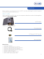
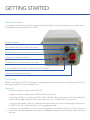
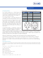
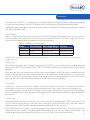
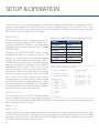
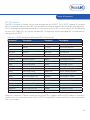
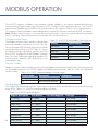
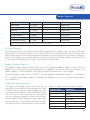
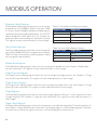
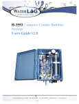
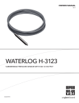
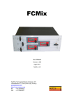
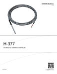
OWNERS MANUAL
V2.3
H-3553T Shown With Optional Display
H-3553T
BUBBLER / PRESSURE SENSOR
D44-03 1115
CONTENTS & WARRANTY
This user manual is a guide for the H-3553T. For more information, updated manuals, brochures,
technical notes, and supporting software on the H-3553T, please refer to
waterlog.com/3553 or contact your sales representative.
For additional assistance, please contact us at +1.435.753.2212 or [email protected]
WaterLOG® Warranty..................................................1
Chapter 1: Introduction...............................................2
Bubbler Features........................................................ 3
Chapter 2: Getting Started.........................................4
What’s in the Box.........................................................5
Product Description.................................................... 6
Initial Testing................................................................6
Power-up...................................................................... 6
Using the Display........................................................ 7
Make Measurement.................................................... 7
Chapter 3: Installation................................................ 8
Water Depth............................................................... 9
Mounting.................................................................... 9
Desiccator................................................................... 9
Orifice Line................................................................. 9
Power Wiring..............................................................10
Chapter 4: Setup & Operation.................................11
RS-232 Menu..............................................................12
RS-232 Print Out........................................................12
SDI-12 Interface.........................................................13
Default Setup.............................................................14
Reset to Defaults....................................................... 14
SDI-12.........................................................................15
Stage Units/Slope......................................................15
Set Current Stage..................................................... 16
Stage Offset...............................................................17
Stage Averaging Time............................................. 17
RS-232 Stage Digits.................................................. 18
Bubble Rate............................................................... 19
Purge.......................................................................... 20
Purge Pressure.......................................................... 20
Purge Sustain............................................................ 21
4-20 Milliamp Output.............................................. 22
4-20 Milliamp Min Stage......................................... 22
4-20 Milliamp Max Stage........................................ 23
Modbus Mode Enable............................................ 24
Auto Mode Enable.................................................. 24
Measure Rate (Auto Mode Enabled)..................... 25
Test Display............................................................... 26
Help........................................................................... 26
Setup and Operation Conclusion.......................... 26
Chapter 5: Modbus Operation...............................27
Communication Setup............................................. 28
Function Codes........................................................ 28
Holding Registers..................................................... 28
ID String Registers.................................................... 29
Modbus Address Register....................................... 29
Stage Units Select Register......................................29
Baudrate Select Registers........................................30
Parity Select Registers.............................................. 30
Bubble Rate Register................................................ 30
Purge Pressure Register........................................... 30
Purge Sustain Register............................................. 30
Purge Register........................................................... 30
Stage Offset Register............................................... 30
Stage Slope Register................................................ 31
Stage Register........................................................... 31
Pressure Register...................................................... 31
Temperature Register............................................... 31
Control Battery Register........................................... 31
Tank Pressure Register............................................. 31
Compressor Battery Register.................................. 31
Modbus Command Examples................................ 31
Contents & Warranty
“WATERLOG™ PRODUCTS MANUFACTURED BY YELLOW SPRINGS INSTRUMENTS CO., INC. are
warranted by Yellow Springs Instruments Co., Inc. (“YSI”) to be free from defects in materials and
workmanship under normal use and service for twelve (12) months from date of shipment unless
otherwise specified in the corresponding YSI pricelist or product manual.
WaterLOG™ products not manufactured, but that are re-sold by YSI, are warranted only to the
limits extended by the original manufacturer. Batteries, desiccant, and other consumables have
no warranty. YSI’s obligation under this warranty is limited to repairing or replacing (YSI’s option)
defective products,which shall be the sole and exclusive remedy under this warranty.
The customer shall assume all costs of removing, reinstalling, and shipping defective products to YSI.
YSI will return such products by surface carrier prepaid within the continental United States of America.
To all other locations, YSI will return such products best way CIP (Port of Entry) INCOTERM® 2010,
prepaid. This warranty shall not apply to any products which have been subjected to modification,
misuse, neglect, improper service, accidents of nature, or shipping damage. This warranty is in lieu
of all other warranties, expressed or implied. The warranty for installation services performed by YSI
such as programming to customer specifications, electrical connections to products manufactured by
YSI, and product specific training, is part of YSI’s product warranty. YSI EXPRESSLY DISCLAIMS AND
EXCLUDES ANY IMPLIED WARRANTIES OF MERCHANTABILITY OR FITNESS FOR A PARTICULAR
PURPOSE. YSI is not liable for any special, indirect, incidental, and/or consequential damages.”
A complete TERMS AND CONDITIONS OF SALE can be viewed at:
http://www.ysi.com/terms-and-conditions.php
1
01 /
2
INTRODUCTION
Introduction
The WaterLOG® H-3553T/ Pressure Sensor is well known for its compact size and combination of a Bubbler
and built-in pressure sensor. The H-3553T has also been referred to as a self-contained “smart” gas purge
system, because it produces a precision constant mass flow of gas.
Designed to measure fluid levels in surface water, ground water and tanks, the H-3553T Modbus or Auto
mode is enabled it will enter the RS-232 menu with any character sent to this port. uses a battery operated
compressor to maintain pressure in an internal tank. A microprocessor determines how much pressure is
needed in the tank, based on the current head pressure, to produce a constant bubble rate. The compressor
and tank replace the dry nitrogen tank used in previous systems to ensure a safer site.
A sophisticated system of sensors and valves to regulate the bubble rate and purge pressure replaces the
sight feed flow controller and pressure regulator (Conoflow system) used in previous systems. A purge feature,
temporarily pumps up the tank and opens a valve to apply high pressure to the orifice line. This feature is
designed to remove any sediment that may have collected in or around the outlet of the orifice line.
The H-3553T is a standalone system to be used with a Data Collection Platform (DCP). Additional programming
options and an H-3553T built-in menu, make the XL series DCP’s a favorite when it comes to selecting a data
logger to pair with this Bubbler.
Key Features:
• Easy to use stand-alone RS-232 menu setup
• Built in calibrated pressure sensor
• No external pressure sensor needed
• RS-485 MODBUS Client/Slave device (available in V1.3 or later)
• Auto update mode, measures itself based on user defined rate
• SDI-12 interface, 4 – 20mA output, and RS-232 data output
Display Features:
• The H-3553T can be purchased with the display or a display kit can be ordered to upgrade the bubbler to include the display.
• Continuous display readout always shows last measured value
• ‘Read’ button causes the H-3553T to initiate a new measurement
• ‘Purge’ button causes the H-3553T to initiate a line purge
• ‘Tank Release’ button causes the H-3553T to release the pressure from the tank
• The adjust knob allows the user to manually set the stage and sensor SDI-12 address
Other Features:
• Provides a continuous gas flow
• Battery operated – Low power
• Microprocessor controlled, “smart” gas system
• One-piece manifold eliminates many potential sources of leaks
• Pressure gauge provides a visual indication of the tank pressure
• Hydrophobic intake membrane, protects compressor
• All components are easily accessible for inspection and maintenance
• Piston type compressor does not use diaphragm
• Provides an internal pressure relief valve
• Compressor is designed and rated for cold temperature operation
• Controlled and monitored as an SDI-12 sensor
3
02 /
4
GETTING STARTED
Getting Started
Before installation, setup and operation of the H-3553T in the field, read through this section for a general
overview of what you have and how to use it.
What’s in the Box
When unpacking your H-3553T, make sure all the components ordered are received and undamaged from
shipping. The basic package includes:
H-3553T Bubbler
*H-3553T shown with optional display
7 Pin Interface Cable
1/4” Tubing to 1/8” NTP Connector
Mounting Hardware
Optional Items:
•
•
•
•
•
•
•
•
H-3553T-DIS. Display kit
H-355-DES-1. Desiccating Air Dryer (600 CF)
H-355-DP-1. Replacement Desiccant for H-355-DES-1
H-355-DES-2. Desiccating Air Dryer (4400 CF)
H-355-DP-2. Replacement Desiccant for H-355-DES-2
H-355-INS. Orifice Installation Kit
H-355-OL. Orifice Line (1000 ft minimum)
H-3551-CABLE. Communication Cable
5
GETTING STARTED
Product Description
It is important to familiarize yourself with the connections before installing a product at the site. Below are
standard connections found on the H-3553T.
Enclosure Breather
RS-232 Menu Setup Port & Cable Connection
Power & Communications Main Interface Connection
Atmospheric PSI Vent for Sensors
Compressor Air Intake Desiccator Connection
Constant Bubble Out Orifice Line Connection 1/8 inch FNPT
Compressor Power (Connect First)
Initial Testing
Before installing the H-3553T in the field, it is a good practice to test the system in the shop or lab. This will
help preparations for a successful field install.
Power Up
Follow these steps to power up the H-3553T:
1. Apply +12v to the “Compressor 12VDC” terminal connections
2. Referring to Table 2-1, connect +12 VDC, GND, and SDI-12 data connections of the 7 wire Main I/O
sensor interface pigtail cable to a SDI-12 master device, such as a WaterLOG® XL series DCP.
3. Verify the connections Table 2-1, and then connect the Main I/O sensor interface pigtail cable to the
H-3553T via the 7 pin “Sensor Interface” military grade connector.
6
4. At power up, the H-3553T will take an initial atmospheric measurement (listen for a “click” while the
sensors are switched to atmosphere) and then if needed the compressor will turn on to initialize the tank
pressure.
Getting Started
Using the Display
The H-3553Ts display has a ‘Read’ button that
when pressed will cause the unit to initiate a new
measurement and update the display. Measurement
requests from an attached SDI-12 data logger will
also cause the display to update.
If the ‘Read’ button is pressed and held until
the display starts flashing, the Adjust screw may
be turned to increase or decrease the current
stage value. Turning the Adjust screw slowly
will change the hundredths (or thousandths
based on the digit setting) digit while turning
the screw fast changes the ones digit. This
allows one control to make both fine and course
adjustments.
Table 2-1: Main I/O Sensor Interface Cable
Colors
Signal
Cable/Bulkhead
Red
Black
Yellow
Blue
Green
Orange
Brown
+12 VDC
GND
SDI-12 Data
4-20mA +
4-20mA RS-485+
RS-485-
F
E
G
C
D
A
B
If the ‘Read’ button is held down while the
H-3553T is being powered up, the display will
show the current SDI-12 address. The SDI-12
address may be changed using the Adjust screw. Turning the Adjust screw will change the address
in the range of 0 to 9. When the Read button is released the new SDI-12 address is saved and the
display switches to the normal stage readout. To change the SDI-12 address again, the power must
be disconnected and the special power-up sequence repeated.
When the ‘Purge’ button is pressed a new measurement will be initiated; following the
measurement, a line purge will begin. For more information see the Purge section in Chapter 4.
When the ‘Tank Release’ button is pressed the valve holding the air in the tank will be opened,
allowing the air stored in the tank to be released. This button can be useful when troubleshooting
the unit.
Make Measurement
Using a SDI-12 master device, like the XL series DCP, send the “0M!” measurement command to the H-3553T.
Wait about 6 seconds, and then send the “0D0!” data command and verify the data retrieved with the example
below.
Data format: “a + A.AA + B.BBB + CC.C + DD.D + E.EE + FF.F”
a = SDI-12 sensor address
A.AA = Stage (Feet)
B.BBB = Pressure (PSI)
CC.C = Temperature (°C)
DD.D = Sensor Interface Battery (Volts)
E.EE = Tank Pressure (PSI)
F.FF = Compressor Battery (Volts)
Example: “0 + 1.35 + 0.585 + 19.8 + 13.6 + 3.55 + 12.3”
7
03 /
8
INSTALLATION
Installation
The WaterLOG® H-3553T is a system with a fully integrated digital pressure transducer specifically designed
for water level monitoring. The H-3553T directly measures dry gas over a broad temperature range.
WARNING! Before proceeding with the installation, please consider the following site preparation steps to
help prevent problems later.
Water Depth
Table 3-1 shows the maximum pressure to which the H-3553T is factory calibrated to measure. The sensor can
survive temporary operation up to twice the maximum rated pressure for the model’s range. However, any
measurements made beyond the rated pressure will be inaccurate.
Table 3-1: Models Pressure Ranges
Model
Pressure Range Water Depth Range* Accuracy
H-3553T-15
0-15 PSI
0-34.60 ft (10.54 m)
±0.007 ft (2.1 mm)
H-3553T-30
0-30 PSI
0-69.20 ft (21 m)
±0.014ft (4.26 mm)
H-3553T-50
0-50 PSI
0-115.35 ft (35.16 m)
±0.023ft (7.03 mm)
*NOTE: Depth calculations are derived from the standard equation that one PSI is generated by a column of water
2.3067 feet deep.
Mounting
Consideration should be taken in properly mounting the H-3553T system. First, attach the included mounting
feet to the H-3553T enclosure. Mount the H-3553T in a location where it will not get jarred or will shift during
operation.
When possible mount all equipment with connectors pointing down so that moisture or condensation that
could rest on the connectors does not penetrate the inner components of the equipment. Also, specifically
with the H-3553T, having it mounted vertically helps prevent moisture from migrating to the valves. If moisture
does migrate, it will migrate first at the bottom of the tank and near the nylon plug.
Desiccator
Generally, an external desiccator is required to dry the compressor intake air. The desiccator prevents
accumulation of moisture in the tank, manifold and other areas in the system. Connect the output of the
desiccator to the port marked “Inlet”. Desiccators which employ “indicating” silica gel have the advantage of
visually showing the status of the desiccant. As the gel becomes saturated with moisture the gel changes from
blue to pink.
Orifice Line
The position and installation of the orifice line is vital to a successful and accurate H-3553T installation. These
are just a few of several things to consider when installing or checking an orifice line installation. Refer to
“Application Note 1005” for more detailed information about orifice line installation.
Be sure the water current or flow is not pushing against the end of the orifice line, as it will cause a pressure
to be placed on the line that is not related to the water depth. Also, be sure the water current or flow is not
pulling or drawing from the end of the orifice line, as this will cause a false lower pressure on
9
GETTING STARTED
the line not related to the water depth. The line should be installed in an area where the flow of water will
remain relatively calm as compared to the real stage changes. Here are a few Do’s and Do not’s on mounting
the line.
Do:
• Mount the outlet in still water.
• Mount the outlet so the last inch or so is almost horizontal, (slightly downward side exit).
• Try to prevent swells in long runs of orifice line (upward then downward sections).
• Use a muffler in more turbulent waters.
Do not:
• Do not mount the outlet facing up stream, downstream, or upwards.
• Do not allow any portion of the line to be lower than the exit point.
• Do not allow “goose necks” in the orifice line.
• Do not use thin walled tubing, only use USGS approved orifice line.
• Do not mount outlet in the wake of an obstruction, bridge pier, rock, etc.
Power Wiring
The H-3553T has two power connections. The first is the 2 position terminal strip labeled “Compressor 12VDC”.
This connection provides power to the compressor and the control valves.It is recommended using heavier
gauge wire (about 18AWG) for this connection and connecting it directly to the gauge station + 12V battery.
The second power connection +12V through the circular connector labeled “Sensor Interface”. This connection
is the power connection for the circuit board or control module board. It is recommended to power the
control module board via the DCP +12V input instead of using the +12V switched output. Table 3-2 shows the
wiring for connecting the H-3553T to an XL Series DCP.
Note: It is recommended to connect the “Compressor
+12VDC” power source first, then the “Sensor Interface”
control module board power second. This is because the
H-3553T makes an initial measurement at power up and
without the compressor and control valves powered the
H-3553T cannot take an atmospheric measurement to adjust
for barometric pressure.
10
Table 3-2: H-3553T to XL Series DCP WIring
H-3553T
Red (+12V)
Black (Gnd)
XL Series DCP
+12V
Gnd (SDI-12)
Yellow (SDI-12)
Data (SDI-12)
04 /
SETUP & OPERATION
11
SETUP & OPERATION
There are three ways to setup and operate the H-3553T, through the RS-232 menu interface, the SDI-12
interface, and through the XL series DCP menu interface. Setup through the XL series DCP menu is not
discussed in this manual but is discussed in the XL series manual. This chapter will focus on setup using the
RS-232 menu interface and the SDI-12 interface.
RS-232 Menu
The RS-232 Menu interface is designed to work with
a terminal emulator program such as HyperTerminal,
TeraTerm, and ProComm. Table 4-1 shows the settings
required to communicate with the H-3553T through
the RS-232 port.
To begin using the RS-232 H-3553T menu interface,
connect the H-3553T to a computer or other DTE
device with 9 pin serial port using the optional
H-3553T 3 pin RS-232 communications cable (H-35313PCABLE). Now, open the terminal emulator program
and press the ‘Enter’ key two times on the computer
keyboard to wake up the H-3553T and enter the
menu. Pressing the ‘Enter’ key once will just force a
measurement and not enter the menu. Pressing the
‘Enter’ key sends a carriage return (CR) and line feed
(LF). Initial H-3553T communication via the RS232
serial port forces a new measurement to be executed
which will print out the message, “Measuring...” When
the new measurement is complete the menu below
will be displayed in the terminal emulator window as
long as the ‘Enter’ key was press two times.
Table 4-1: H-3553T RS-232 Communication Settings
Setting
Baud Rate
Data Bits
Default Setting
9600
8
Stop Bits
Parity
Duplex
Emulation
Flow Control
1
None
Full
VT-100
None
RS-232 Print Out
The RS-232 port on the H-3553T is primarily used for
setup and operation, but can also be used for sending
the current stage and temperature data. When the H-3553T makes a new measurement it will print the following
data message out the RS-232 port.
Stage = +1.23
Temp = +12.3
The RS-232 port can also be used to initiate new measurements. This is done by sending any character to the
H-3553T RS-232 port and the H-3553T will make a new measurement and print out the above mentioned data
message out the RS-232 port. Note: When the H-3553T Modbus or Auto mode is enabled it will enter the RS232 menu with any character sent to this port.
12
Setup & Operation
SDI-12 Interface
The SDI-12 interface is another way to setup and operate the H-3553T. The H-3553T supports all standard
SDI-12 commands and uses some SDI-12 extended (manufacturer specific) commands for setup operation.
SDI-12 standard and extended commands are normally sent from a SDI-12 master device, like the Waterlog
XL series DCP. Table 4-2 is a list of the standard SDI-12 commands and the extended SDI-12 commands for
setting up the H-3553T.
Table 4-2: H-3553T Standard and Extended SDI-12 Commands
Command
Description
Command
Description
Standard SDI-12 Commands
a!
Acknowledge
aM2!
Initiate Purge
al!
Identify
aC!-aC9!
Concurrent Measure
aV!
Verify
aCC!-aCC9!
Concurrent measure w/CRC
aM!-aM1!
Measure
aD0!-aD9!
Data Retrieval
aMC!-MC1!
Measure with CRC
aAn!
Change Address
Extended SDI-12 Commands
aXSDEF!
Reset to Defaults
aXRPP!
Read Purge Pressure
aXWSn.nn!
Write Stage Slope
aXWPSnn!
Write Purge Sustain
aXRS!
Read Stage Slope
aXRPS!
Read Purge Sustain
aXSCSn.nn!
Set Current Stage
aXWIHn.nn!
Write 4-20mA Stage max
aXWOn.nn!
Write Stage Offset
aXRIH!
Read 4-20mA Stage Max
aXRO!
Read Stage Offset
aXWILn.nn!
Write 4-20mA Stage Min
aXWATnn!
Write Averaging Time
aXRIL!
Read 4-20mA Stage Min
aXRAT!
Read Averaging Time
aXWMEn!
Write Modbus enable
aXWSDn!
Write RS-232 Stage Digits
aXRMEn!
Read Modbus enable
aXRSD!
Read RS-232 Stage Digits
aXWAEn!
Write Auto enable
aXWBRnn!
Write Bubble Rate
aXRAEn!
Read Auto enable
aXRBR!
Read Bubble Rate
aXWMRnn!
Write Measure Rate
aXWPPnn!
Write Purge Pressure
aXRMR!
Read Measure Rate
aXTD!
Test Display
aXHELP!
Display a List of Commands
Note, the ‘a’ character in Table 4-2 represents the current SDI-12 address of the H-3553T and the ‘n’ characters
represent the new value to be written. Each H-3553T extended SDI-12 command is discussed in more detail
later in the chapter.
13
SETUP & OPERATION
Default Setup
The H-3553T has many settings that can be change. However, the default setups will normally cover most
applications. Table 4-3 shows the default settings for the H-3553T.
Table 4-3: H-3553T Default Setup
Setting
SDI-12 Address
Stage Units
Default Setting
Setting Range
0
0-9 (Standard), A-Z, a-z
Feet (Slope = 2.3067) Ft, In, M, mm, Ft Dn, Usr Def
Stage Offset
SDI-12 Stage Digits
RS-232 Stage Digits
Averaging Time
Bubble Rate
Purge Pressure
0.00
3
2
2 Seconds
60 bubbles/min
40 PSI (15 PSI Sensor)
50 PSI (30 PSI Sensor)
20 seconds
4.0
20.0
Purge Sustain
4-20mA Min Stage
4-20mA Max Stage
N/A
N/A
1-65535 seconds
30-120 bubbles/min
30-90 PSI
10-40 seconds
N/A
N/A
Reset to Defaults
It may be necessary to reset the H-3553T settings back to factory defaults. Using the RS-232 menu, press the
‘P’ key to enter the “ Advanced Options” menu and then press the ‘D’ key to “ Reset Defaults”.
To reset to defaults using the SDI-12 interface, send the “aXSDEF!” SDI-12 extended command. The response
should be “a0041” which means that it will take 4 seconds to reset to defaults. Note in Table 4-4, the ‘a’ is the
current address of the H-3553T.
Table 4-4: Reset H-3553T to Factory Defaults
H-3553T Combo Bubbler Setup Menu
P - Advanced Options
:
Advanced Options Menu
D - Reset Defaults
Resetting to Defaults...
14
SDI-12 Interface
Command: aXSDEF!
Response: a0041
Setup & Operation
SDI-12
The SDI-12 address of a sensor is its identifier on the SDI-12 data bus. The SDI-12 data bus is a one wire
communication between normally one master device and one or more slave devices. The SDI-12 address
makes it possible for the master device to communicate with each sensor individually. SDI-12 data collisions
will occur when two or more sensors have the same address on the same data bus. The sensors with the same
address will try to respond to the request of the master device at the same time and the result is garbage data.
Therefore, it is important to know the address of the sensor to which communication is desired and that there
are no other sensors with the same address.
The H-3553T SDI-12 address by
default is 0. To change the H-3553T
SDI-12 address using the RS-232 main
menu, press the ‘A’ key and enter in
the new “ SDI-12 address”.
Table 4-5: Change the H-3553T SDI-12 Address
H-3553T Combo Bubbler Setup Menu
A - SDI-12 Address: a
Enter New SDI-12 Address [n]
SDI-12 Interface
Command: aAn!
Response: n
To change the H-3553T SDI-12 address using the SDI-12 interface, send the “aAn!” command and the response
should be ‘n’, the new address. Note in Table 4-5, the ‘a’ is the current address of the H-3553T and the ‘n’ is
the desired new SDI-12 address.
Stage Units / Slope
The stage unit of a sensor is the setting that determines the
data output units. Different data units are dependent on the
slope/multiplier. The slope is multiplied by the raw data to
achieve the desired units. For example, a pressure sensor raw
data output might be in pressure (PSI) units, but the desired
units by the user is feet. Therefore, the slope to convert PSI to
Feet units for water depth is 2.0367 rounded.
Table 4-6: H-3553T Stage Units and Slopes
Units
Feet
Meters
Inches
Slopes (multiplier)
2.3067
0.7031
27.6800
Millimeters
0.0007031
0.007031
The H-3553T has a pressure sensor that measures the Centimeters
-2.3067
pressure required to push a bubble out of the orifice line, Feet Down
which is the line pressure. The line pressure raw value is PSI
1.0000
returned in pressure (PSI) units. Normally, water depth in feet
or meters is the stage units desired. This then requires the line pressure value to be changed to a different set
of units. Table 4-6 shows typical slopes required to convert pressure (PSI) units to other different stage units.
The H-3553T stage unit default is feet, which is a default slope of 2.0367. To change the stage units/slope
using the RS-232 main menu, press the ‘U’ key and then the up and down arrow keys to toggle to the desired
units, then press the ‘Enter’ key. If the desired stage unit is not listed change the stage units to user defined,
press the ‘L’ key and enter in the desired slope.
To change the H-3553T stage slope using the SDI-12 interface, send the “aXWSn.nn!” SDI-12 extended
command. The response should be “a0021” which means that it will take 2 seconds to complete the command
and then it will put 1 data value in the buffer. To check the slope and verify it was written correctly send “aXRS!”
and wait the responded time. Then send the “aD0!” command to read back the new slope.
15
SETUP & OPERATION
Note Table 4-7, the ‘a’ is the current SDI-12 address of the H-3553T and the ‘xxxx’/’x.xxx’ is the current units/
slope of the H-3553T and the ‘nnnn’/’n.nnn’ is the desired new units/slope.
Table 4-7: Change the H-3553T Units / Slope
H-3553T Combo Bubbler Setup Menu
U - Units: xxxx
Stage Units: [nnnn]
SDI-12 Interface
Command: aXWSn.nnn!
Response: a0021
L - Slope: x.xxx
Enter Slope Value: [n.nnn]
Command: aXRS!
Response: a0011
Command: aD0!
Response: a + n.nnn
Set Current Stage
Set current stage is setting the stage to the actual measured or surveyed value, this could include the elevation
or not. Normally, the current stage value comes from a wire weight reading or a surveyed staff gauge reading.
Setting the current stage in the H-3553T forces a new measurement and then compares the result of that
measurement with the desired current stage and then calculates and sets the stage offset. To set the current
stage using the RS-232 main menu, press the ‘S’ key, enter in the current “Stage” and then press the ‘Enter’
key.
To set current stage using the SDI-12 interface, send the “aXSCSn.nn!” SDI-12 extended command. The
response should be “a0061” which means that it will take 6 seconds to complete the command and then it will
put 1 data value in the buffer. To check if the stage was set correctly, send the “aM!” measurement command,
wait the responded time and then send the “aD0” and verify the stage level value. Note Table 4-8, the ‘a’ is the
current SDI-12 address of the H-3553T and the ‘x.xxx’ is the current measured stage of the H-3553T and the
’n.nnn’ is the desired new current stage.
Table 4-8: Set the H-3553T Current Stage
H-3553T Combo Bubbler Setup Menu
S - Stage: x.xxx
Enter Stage Value: [n.nnn]
SDI-12 Interface
Command: aXSCSn.nnn!
Response: a0061
Command: aM!
Response: a0066
Command: aD0!
Response: a+n.nnn+...
Note: The last section of this chapter discusses the “Set Current Stage” section as the most used option.
16
Setup & Operation
Stage Offset
The stage offset is a value that is added to the final stage result after the slope/multiplier has been applied.
The stage offset is normally used to obtain a final stage level relative to some reference point such as sea level.
Writing the stage offset is not needed when using the set current stage option, because this option calculates
and sets the stage offset automatically.
The H-3553T stage offset default is 0.000. To change the stage “ Offset” using the RS-232 main menu, press
the ‘O’ key, enter the new stage offset and then press the ‘Enter’ key.
To change the H-3553T stage offset using the SDI-12 interface, send the “aXWOn.nn!” SDI-12 extended
command. The response should be “a0021” which means that it will take 2 seconds to complete the command
and then it will put 1 data value in the buffer. To check the offset and verify it was written correctly send “aXRO!”
and wait the responded time. Then send the “aD0!” command to read back the new offset. Note Table 4-9,
the ‘a’ is the current SDI-12 address of the H-3553T and the ‘x.xxx’ is the current offset of the H-3553T and the
’n.nnn’ is the desired new stage offset.
Table 4-9: Change the H-3553T Stage Offset
H-3553T Combo Bubbler Setup Menu
O - Offset: x.xxx
Enter Offset Value: [n.nnn]
SDI-12 Interface
Command: aXWOn.nnn!
Response: a0021
Command: aXRO!
Response: a0011
Command: aD0!
Response: a + n.nnn
Stage Averaging Time
The stage averaging time is the setting that determines how long in seconds the H-3553T will average the
measurements before returning the final stage value. It is important to sample multiple times to ensure
accuracy of a reading, especially if the water is rough. The stage averaging time may need to be adjusted to
help smooth out choppy data due to wave action.
The H-3553T stage averaging time default is 2 seconds, which is equal to about 10 samples. The stage
averaging time range is 1 to 65535 seconds. To change the averaging time using the RS-232 main menu,
press the ‘P’ key to enter the “Advanced Options” menu, then press the ‘T’ key, enter in the new “Averaging
Time” and press the ‘Enter’ key.
To set the stage averaging time using the SDI-12 interface, send the “aXWATnn!” SDI-12 extended command.
The response should be “a0021” which means that it will take 2 seconds to complete the command and then
it will put 1 data value in the buffer. To check if the averaging time was set correctly, send “aXRAT!” command,
wait the responded time and then send the “aD0” and verify the averaging time value. Note Table 4-10, the ‘a’
is the current SDI-12 address of the H-3553T and the ‘x’ is the current averaging time of the H-3553T and the
‘n’ is the desired stage averaging time.
17
SETUP & OPERATION
Note: This averaging time does not take into account the time it takes to make an atmospheric reading.
Therefore, always add about 4 more seconds to the averaging time to calculate how long the full measurement
cycle can take.
Table 4-10: Change the H-3553T Stage Averaging Time
H-3553T Combo Bubbler Setup Menu
P – Advanced Options
:
SDI-12 Interface
Command: aXWATn!
Response: a0021
Advanced Options Menu
T – Averaging Time: x
Averaging Time [ nnn ]
Command: aXRAT!
Response: a0011
Command: aD0!
Response: a + nnn
RS-232 Stage Digits
The RS-232 stage digits are the setting that determines how many digits are displayed to the right of the
decimal place for the measured value when printed out the RS-232 port. Normally, two digits to the right of
the decimal place is the standard when measuring stage in feet.
The H-3553T RS-232 stage digits default is 2. To change the “Stage Digits” using the RS-232 main menu, press
the ‘D’ key, enter in the new stage digits and then press the ‘Enter’ key.
To change the H-3553T RS-232 stage digits using the SDI-12 interface, send the “aXWSDn!” SDI-12 extended
command. The response should be “a0021” which means that it will take 2 seconds to complete the command
and then it will put 1 data value in the buffer. To check the stage digits and verify it was written correctly send
“aXRSD!” and wait the responded time. Then send the “aD0!” command to read back the new stage digits.
Note Table 4-11, the ‘a’ is the current SDI-12 address of the H-3553T and the ‘x’ is the current stage digits of
the H-3553T and the ‘n’ is the desired new stage digits.
Table 4-11: Change the H-3553T RS-232 Stage Digits
H-3553T Combo Bubbler Setup Menu
D - Digits: x
Stage Digits: [n]
SDI-12 Interface
Command: aXWSDn!
Response: a0021
Command: aXRSD!
Response: a0011
Command: aD0!
Response: a+n
18
Setup & Operation
Bubble Rate
The bubble rate is the average number of bubbles flowing Table 4-12: Bubble Rate vs. Response Time
from the end of the orifice line per minute. The standard Bubble Rate
Response for 1 Ft. Rise
orifice line tubing that we recommend and calibrate the
30 bubbles/min
25 seconds
bubble rate has 1/8 inch inner diameter (I.D.). If a different
60 bubbles/min
20 seconds
size orifice I.D. is used the bubble rate will not be correct.
120 bubbles/min
15 seconds
The bubble rate is a determining factor in the response
time of the H-3553T tracking a rise in stage. Table 4-12
shows the approximate time needed to respond and track a one foot rise in stage with different bubble rates.
Note this is at a depth of one foot, at greater depths the time will increase slightly.
Another reason for changing the bubble rate may be to reduce noise in the data. Some sites have turbulent
water conditions creating water level data that looks jittery. The bubble rate may be changed, up or down, to
find optimal results to reduce this noise. Normally, it is a combination of changing the bubble rate and the
mean count/samples to produce the best results. The default values normally work best in the majority of the
applications and provide desirable results in a timely manner.
The H-3553T bubble rate default is set to 60 bubbles/min. The bubble rate range is 30 to 120 bubbles/min. To
change the bubble rate using the RS-232 main menu, press the ‘B’ key to enter the “Bubbler Settings” menu,
then press the ‘B’ key, enter in the new desired “Bubble Rate” and press the ‘Enter’ key.
To change the H-3553T bubble rate using the SDI-12 interface, send the “aXWBRnn!” SDI-12 extended
command. The response should be “a0061” which means that it could take 6 seconds to complete the
command and then it will put 1 data value in the buffer. To check the bubble rate and verify it was written
correctly send “aXRBR!” command and wait the responded time. Then send the “aD0!” command to read
back the new bubble rate. Note Table 4-13, the ‘a’ is the current SDI-12 address of the H-3553T and the ‘xx’ is
the current bubble rate of the H-3553T and the ‘nn’ is the desired bubble rate.
Table 4-13: Change the H-3553T Bubble Rate
H-3553T Combo Bubbler Setup Menu
B – Bubbler Settings
:
SDI-12 Interface
Command: aXWBRnn!
Response: a0061
Bubbler Settings Menu
B – Bubbler Rate: xx
Enter Bubble Rate (30 -120) [ nn ]
Command: aXRBR!
Response: a0021
Command: aD0!
Response: a + nn
19
SETUP & OPERATION
Purge
The H-3553T has an option built in called purge, the purpose of the purge
is to clear out any debris or silt from the end of the orifice line that could cause false pressure readings.
When a purge is initiated the H-3553T makes a new measurement on the line and tank sensor and saves the
values away just in case data is requested during the purge. The compressor is then turned on and begins
compressing air into the tank until the tank pressure is equal to or greater than the purge pressure value.
The purge valve is then opened which then releases the tank pressure into the orifice line. The compressor
will continue to run until the purge sustain timer has elapsed. Then the H-3553T monitors the tank pressure
which is still open to the orifice and waits for it to stabilize. Finally, the purge valve closes and the H-3553T
purge process is complete. Shortly following the purge sequence the H-3553T will need to recharge the tank
pressure to maintain the bubble rate and continue normal operation.
There are three ways to initiate a purge, push the “PURGE” button, the RS-232 menu, and the SDI-12 interface.
To initiate a purge with the button, open the H-3553T enclosure lid and locate the a white push button on the
circuit board labeled “PURGE”, press and hold for about 2 seconds.
To initiate a purge using the RS-232 main menu, press ‘B’ key to enter the “Bubbler Settings” menu and then
press the ‘M’ key for “Manual Purge”. To initiate a purge using the SDI-12 interface, send the “aXP!” command
or the “aM2!” command. Note Table 4-14, the ‘a’ is the current SDI-12 address of the H-3553T. The ‘ttt’ is the
time it will take to complete the purge, which is dependent on other factors like averaging time and purge
sustain. The ‘dd.d’ is the compressor battery voltage measured immediately following the completed purge
sequence.
Table 4-14: Initiate H-3553T Purge
H-3553T Combo Bubbler Setup Menu
B – Bubbler Settings
:
SDI-12 Interface
Command: aXP! / aM2!
Response: attt1
Bubbler Settings Menu
M – Manual Purge
Initiating Purge . . .
Command: a + dd.d
Response: a + dd.d
Purge Pressure
The purge pressure is the pressure that is used to purge the orifice line. This is normally done to clear the end
of the orifice line of debris and or sediment buildup. “False high stage” readings can be caused by debris or
sediment buildup at the end of the orifice line. This is because it will cause more restriction when trying to
push a bubble out which is like the stage is rising. This may cause a saw tooth profile in your data. As pressure
keeps building up until the bubble pushes out past the debris or sediment relieving the pressure in the line.
Then the pressure starts building up again causing saw tooth data.
The H-3553T purge pressure default is set to 40 PSI (15 PSI sensor) or 50 PSI (30 PSI sensor). The programmable
purge pressure range is 30 to 90 PSI. To change the “Purge Pressure” using the RS-232 main menu, press the
20
Setup & Operation
‘B’ key to enter the “Bubbler Settings” menu and then press the ‘P’ key, then enter in the desired purge
pressure and press the ‘Enter’ key.
To change the H-3553T purge pressure using the SDI-12 interface, send the “aXWPPnn!” SDI-12 extended
command. The response should be “a0061”, which means that it could take 6 seconds to complete the
command and then it will put 1 data value in the buffer. To check the new purge pressure, send “aXRPP!”
command and wait the responded time. Send the “aD0!” command to read back the new written purge
pressure. Note Table 4-15, the ‘a’ is the current SDI-12 address of the H-3553T and the ‘xx’ is the current purge
pressure of the H-3553T and the ‘nn’ is the desired purge pressure.
Table 4-15: Change the H-3553T Purge Pressure
H-3553T Combo Bubbler Setup Menu
B – Bubbler Settings
:
SDI-12 Interface
Command: aXWPPnn!
Response: a0061
Bubbler Settings Menu
P – Purge Pressure: xx
Enter Purge Pressure (15 - 90) [ nn ]
Command: aXRPP!
Response: a0021
Command: aD0!
Response: a + nn
Purge Sustain
The purge sustain is part of the purge sequence discussed earlier, it is the time in seconds that the compressor
will keep running after the tank pressure is released into the orifice line. The purge sustain helps clear out
heavier sediment buildup and or bigger blocks at the end of the orifice because of sustaining a higher
pressure.
The H-3553T purge sustain default time is set to 20 seconds. The programmable purge sustain range is 10
to 40 seconds. To change the purge sustain time using the RS-232 main menu, press the ‘B’ key to enter the
“Bubbler Settings” menu and then press the ‘S’ key, enter in the desired “Purge Sustain” time and then press
the ‘Enter’ key.
To change the H-3553T purge sustain using the SDI-12 interface; send the “aXWPSnn!” SDI-12 extended
command. The response should be “a0061”, which means that it could take 6 seconds to complete the
command and then it will put 1 data value in the buffer. To check the new purge sustain time, send “aXRPS!”
command and wait the responded time. Send the “aD0!” command to read back the new written purge
sustain time. Note Table 4-16, the ‘a’ is the current SDI-12 address of the H-3553T and the ‘xx’ is the current
purge sustain time of the H-3553T and the ‘nn’ is the desired purge sustain time.
21
SETUP & OPERATION
Table 4-16: Change the H-3553T Purge Sustain
H-3553T Combo Bubbler Setup Menu
B – Bubbler Settings
:
SDI-12 Interface
Command: aXWPSnn!
Response: a0061
Bubbler Settings Menu
S – Purge Sustain: xx
Enter Purge Sustain (10 - 40) [ nn ]
Command: aXRPS!
Response: a0021
Command: aD0!
Response: a + nn
4-20 Milliamp Output
The H-3553T has the ability to output the
stage value as a 4-20 milliamp signal. The
4-20 milliamp output is most commonly
used in industrial applications with PLC’s
or SCADA systems. The H-3553T controls
the loop current but does not power the
loop. Therefore, the loop must be externally
powered. Figure 4-1 shows a basic wiring
diagram for a 4-20 milliamp output loop with
the H-3553T. The battery in the loop should
be a +24VDC power source.
Figure 4-1: Typical H-3553T 4-20 mA Output Setup
The H-3553T scales the current measured stage reading for the 4-20 milliamp output based on the 4-20
milliamp min and max stage values.
4-20 Milliamp Min Stage
The 4-20 milliamp min stage value should be the lowest the stage gets at the installed site. When the stage
equals this value or lower the 4-20 milliamp out put will be 4.0 milliamps, the min.
The H-3553T 4-20 milliamp min stage default value is set to 4. There is no limit to this value, but keep in mind
that the smaller the overall range of the 4-20 stage scalar, which is the min to the max stage, the more accurate
the 4-20 milliamp output will be. To change the 4-20 milliamp min stage using the RS-232 main menu, press
the ‘P’ key to enter the “Advanced Options” menu and then press the ‘F’ key to enter the “4-20mA Output
Setup” menu. Then press the ‘N’ key in this menu and enter in the new “Min Stage” value and press the ‘Enter’
key.
To change the H-3553T 4-20 milliamp min stage using the SDI-12 interface, send the “aXWILn.nn!” SDI-12
extended command. The response should be “a0021”, which means that it could take 2 seconds to complete
the command and then it will put 1 data value in the buffer. To check the new 4-20 milliamp min stage, send
“aXRIL!” command and wait the responded time. Then send the “aD0!” command to read back the new written
4-20 milliamp min stage. Note Table 4-17, the ‘a’ is the current SDI-12 address of the H-3553T and the ‘x.xx’
is the current 4-20 milliamp min stage and the ‘n.nn’ is the desired 4-20 milliamp min stage.
22
Setup & Operation
Table 4-17: Change the H-3553T 4-20 Milliamp Min Stage
H-3553T Combo Bubbler Setup Menu
P – Advanced Options
:
SDI-12 Interface
Command: aXWILn.nn!
Response: a0021
Advanced Options Menu
F – 4-20 mA Output
:
4-20 mA Output Setup Menu
N – Min Stage: x.xx
Enter 4 - 20mA Min Stage [ n.nn ]
Command: aXRIL!
Response: a0011
Command: aD0!
Response: a + n.nn
4-20 Milliamp Max Stage
The 4-20 milliamp max stage value should be the highest the stage gets at the installed site. When the stage
equals this value or greater the 4-20 milliamp output will be 20.0 milliamps, the max.
The H-3553T 4-20 milliamp max stage default value is set to 20. There is no limit to this value, but keep in mind
that the smaller the overall range of the 4-20 stage scalar, which is the min to the max stage, the more accurate
the 4-20 milliamp output will be. To change the 4-20 milliamp max stage using the RS-232 main menu, press
the ‘P’ key to enter the “Advanced Options” menu and then press the ‘F’ key to enter the “4-20mA Output
Setup” menu. Then press the ‘X’ key in this menu, enter in the new “Max Stage ” value and press the ‘Enter’ key.
To change the H-3553T 4-20 milliamp max stage using the SDI-12 interface, send the “aXWIHn.nn!” SDI-12
extended command. The response should be “a0021”, which means that it could take 2 seconds to complete
the command and then it will put 1 data value in the buffer. To check the new 4-20 milliamp max stage, send
“aXRIH!” command and wait the responded time. Then send the “aD0!” command to read back the new
written 4-20 milliamp max stage. Note Table 4-18, the ‘a’ is the current SDI-12 address of the H-3553T and the
‘x.xx’ is the current 4-20 milliamp max stage and the ‘n.nn’ is the desired 4-20 milliamp max stage.
Table 4-18: Change the H-3553T 4-20 Milliamp Max Stage
H-3553T Combo Bubbler Setup Menu
P – Advanced Options
:
SDI-12 Interface
Command: aXWIHn.nn!
Response: a0021
Advanced Options Menu
F – 4-20 mA Output
:
4-20 mA Output Setup Menu
X – Min Stage: x.xx
Enter 4 - 20mA Max Stage [ n.nn ]
Command: aXRIH!
Response: a0011
Command: aD0!
Response: a + n.nn
23
SETUP & OPERATION
Modbus Mode Enable
The Modbus mode enable is the setting that determines whether the H-3553T will communicate with a Modbus
master device. Modbus is an industry standard serial digital interface for interconnecting Programmable
Logic Controllers (PLCs), intelligent sensors and other devices. The H-3553T can be used as a Modbus slave
and has a serial RS-485 port for connecting to a Modbus compatible host device. See the “Chapter 5 Modbus
Operation” for more information on Modbus settings Modbus register definitions. Note: this mode requires
more power because it does not go to sleep, the normal operation current draw increase to about 14mA
instead of normal mode of about 6mA.
The H-3553T Modbus mode enable default is 0 meaning disabled/off. To enable the “Modbus Mode” using
the RS-232 main menu, press the ‘P’ key to enter the “Advanced Options” menu and then press the ‘M’ key
to enter the “Modbus Setup” menu. Then press the ‘M’ key in this menu and the Modbus mode enable will
change to on.
To change the H-3553T Modbus mode enable using the SDI-12 interface, send the “aXWME1!” SDI-12
extended command to enable or change the ‘1’ to a 0 to disable. The response should be “a0021” which
means that it will take 2 seconds to complete the command and then it will put 1 data value in the buffer. To
check the Modbus mode enable and verify it was written correctly send “aXRME!” and wait the responded
time. Then send the “aD0!” command to read back the Modbus mode enable. Note Table 4-19, the ‘a’ is the
current SDI-12 address of the H-3553T and the ‘n’ is the desired Modbus mode enable “1 = On” or “0 = Off”.
Table 4-19: Change the H-3553T Modbus Mode Enable
H-3553T Combo Bubbler Setup Menu
P – Advanced Options
:
SDI-12 Interface
Command: aXWMEn!
Response: a0021
Advanced Options Menu
M – Modbus Setup
:
Modbus Settings Menu
M - Modbus Off/On
Command: aXRME!
Response: a0021
Command: aD0!
Response: a + n
Auto Mode Enable
The Auto mode enable is the setting that determines whether the H-3553T is put in a unique mode. When
in this mode the H-3553T does not go to sleep but stays awake and based on a user defined measure rate
measures itself and updates all the output s like 4-20mA, RS-232, and the SDI-12 buffer. This mode makes it
possible for the H-3553T to run on its own completely independent of a data logger or master device. Note:
this mode requires more power because it does not go to sleep, the normal operation current draw increase
to about 14mA instead of normal mode of about 6mA.
The H-3553T Auto mode enable default is 0 meaning disabled/off. To enable the “Auto Mode” using the
24
Setup & Operation
RS-232 main menu, press the ‘P’ key to enter the “Advanced Options” menu. Then under the “Measurement
Options” section press the ‘A’ key and the Auto mode enable will change to on.
To change the H-3553T Auto mode enable using the SDI-12 interface, send the “aXWAE1!” SDI-12 extended
command to enable or change the ‘1’ to a 0 to disable. The response should be “a0021” which means that it
will take 2 seconds to complete the command and then it will put 1 data value in the buffer. To check the Auto
mode enable and verify it was written correctly send “aXRAE!” and wait the responded time. Then send the
“aD0!” command to read back the Auto mode enable. Note Table 4-20, the ‘a’ is the current SDI-12 address of
the H-3553T and the ‘n’ is the desired Auto mode enable “1 = On” or “0 = Off”.
Table 4-20: Change the H-3553T Auto Mode Enable
H-3553T Combo Bubbler Setup Menu
P – Advanced Options
:
SDI-12 Interface
Command: aXWAEn!
Response: a0021
Advanced Options Menu
A – Automode Off/On
Command: aXRAE!
Response: a0021
Command: aD0!
Response: a + n
Measure Rate (Auto Mode Enabled)
The Measure Rate is the time in minutes the H-3553T will update itself and outputs when in auto mode (see
section Auto Mode Enable). This is useful in the application where the H-3553T is no connected to a master
device to say when to measure and give data.
The H-3553T Measure Rate default time is set to 1 minute. The programmable measure rate range is 0 to 255
minutes. Note: When the measure rate is set to 0 minutes the H-3553T will measure itself as fast as it can.
This speed is dependent on the averaging time setting and also when doing this the atmospheric pressure
reading will be measured about every 3 ½ minutes rather than every measurement. To change the measure
rate
using the RS-232 main menu, press the ‘P’ key to enter the “Advanced Options” menu. Then found under the
“Measurement Options” section, press the ‘R’ key and enter in the desired auto mode measure rate.
To change the H-3553T measure rate using the SDI-12 interface, send the “aXWMRnn!” SDI -12 extended
command. The response should be “a0021”, which means that it could take 2 seconds to complete the
command and then it will put 1 data value in the buffer. To check the new measure rate, send “aXRMR!”
command and wait the responded time. Send the “aD0!” command to read back the new written measure
rate. Note Table 4-21, the ‘a’ is the current SDI-12 address of the H-3553T and the ‘xx’ is the current measure
rate of the H-3553T and the ‘nnn’ is the desired measure rate time.
25
SETUP & OPERATION
Table 4-21: Change the H-3553T Measure Rate
H-3553T Combo Bubbler Setup Menu
P – Advanced Options
:
SDI-12 Interface
Command: aXWMRnnn!
Response: a0021
Advanced Options Menu
R - Measure Rate: xx
Enter Measure Rate (0 - 255) [nnn ]
Command: aXRMR!
Response: a0021
Command: aD0!
Response: a + nnn
Test Display
If the display seems to be displaying numbers incorrectly, the Test Display command can be used to verify the
individual segments are working properly. This command cycles the numbers 0-9 in each number location
then displays 100.000, 1000.00, and 10000.0 to ensure the decimals are also working properly.
Help
The Help command outputs a complete list of commands that this unit supports. The response is not SDI-12
compliant but many devices in a transparent mode can display the table of commands.
Setup and Operation Conclusion
This chapter has focused on the setup and operation of the H-3553T. Although there are many settings,
most applications will work just fine with the default settings. WaterLOG has put great efforts in testing and
adjusting the default settings to fit most applications, therefore try using the default settings, and then make
adjustments as needed.
The option that will probably be of most importance in this chapter is the “Set Current Stage” section. Once
the H-3553T is mounted and installed, the last thing to do is set the current stage. All the other settings found
in this chapter will only need to be changed if the default settings will not work for the application.
And of course, with all WaterLOG equipment, if there is ever a question or more explanation needed or a
problem that needs extra assistance call or email us and we will gladly assist you with the product.
Phone: 435-753-2212
Email: [email protected] or [email protected]
26
05 /
MODBUS
OPERATION
27
MODBUS OPERATION
The H-3553T supports a Modbus client protocol interface. Modbus is an industry standard field bus for
interconnecting Programmable Logic Controllers (PLCs), intelligent sensors and other devices. The H-3553T
communicates Modbus via the RS-485 serial port connections; see Chapter 2 Table 2-1 for wiring connections.
This chapter will focus on Modbus setup and operation using the RS-232 menu interface or the SDI-12 interface.
Note: Modbus communication is only available when the system is not busy performing other requested
tasks (i.e. purging, automode with the rate set to zero, SDI-12 commands, etc.)
Communication Setup
The Modbus communication interface is designed to
work with a Modbus Host device like PLC’s, etc. The
host must support RTU (Remote Terminal Unit) mode
to communicate with the H-3553T. Table 5-1 shows
the default settings required to communicate with
the H-3553T through the RS-485 Modbus interface
port. For more information regarding Modbus RTU
communication protocol and specifications see
www.modbus.org.
Table 5-1: H-3553T RS-485 Modbus Comm Settings
Setting
Baud Rate
Data Bits
Default Setting
9600
8
Stop Bits
Parity
Protocol
1
Even
RTU
Function Codes
Modbus Function Codes are codes that are part of the Modbus command that specify what is being requested
via the Modbus protocol. The H-3555 supports two Modbus function codes. Table 5-2 shows the supported
function codes.
Table 5-2: H-3553T Supported Modbus Function Codes
Function Code
03
16
Description
Read Holding Registers
Write Multiple Registers
# of Registers
41
41
Holding Registers
The H-3553T has 41Holding Registers; these registers contain all the needed data for setup and measuring
the H-3553T. Table 5-3 is a list of the holding registers available.
Table 5-3: H-3553T Holding Registers
28
Register Description
*ID String
Modbus Address
Start Address
0/ “0000”
16 / “0010”
# of 16-bit Registers
16
1
Data Type
Char String
Short Integer
Stage Units
17 / “0011”
1
Short Integer
Reserved
18 / “0012”
1
Short Integer
Baudrate
19 / “0013”
1
Short Integer
Parity
Bubble Rate
20 / “0014”
21 / “0015”
1
1
Short Integer
Short Integer
Purge Pressure
22 / “0016”
1
Short Integer
Purge Sustain
23 / “0017”
1
Short Integer
Purge
24 / “0018”
1
Short Integer
Modbus Operation
Stage Offset
Stage Slope
25 / “0019”
27 / “001B”
2
2
32 Bit Float
32 Bit Float
*Stage
29 / “001D”
2
32 Bit Float
*Pressure
31 / “001F”
2
32 Bit Float
*Temperature
33 / “0021”
2
32 Bit Float
*Control Battery
*Tank Pressure
35/“0023”
37 / “0025”
2
2
32 Bit Float
32 Bit Float
*Compressor Battery
39 / “0027”
2
32 Bit Float
*Note: These registers are read only; there is no effect if written.
ID String Registers
The ID String is the first set of registers in the Holding Registers; these registers return the same information
that the SDI-12 ID command returns. The ID string consists of 16, 16-bit registers in ASCII character data
format. These registers can be read separately but to get the full ID string the user must read all 16-registers
at once. These registers are read only registers; however, writing to them will have no effect. As shown in Table
5-3 the response to reading the ID string is sent as ASCII character string.
Modbus Address Register
The Modbus Address holding register allows the user to change the Modbus address of the H-3553T. A
Modbus host / master device can be connected to many Modbus slave devices at one time. Therefore, the
Modbus address is a device identifier. This register must be read and wrote as a short integer.
The default Modbus address for the H-3553T is 1 and the programmable address range is: 1 - 247. Address
“0” is reserved as the broadcast address meaning that all Modbus sensors must listen when commands are
sent to address “0”.
Stage Units Select Register
The Stage Units holding registers allows the user to
change the units of the final measured stage value. Table
5-4 shows what the stage units holding register must be
set to obtain the desired units. The H-3553T default stage
units are in feet. In the case that there is a user defined
units, first change the stage units select to ‘06’ and then
write the slope manually. Writing the stage slope before
setting stage units to user defined will have no effect.
This register must be read and wrote as a short integer.
Table 5-4: Stage Units Select Register Options
Register Value
00
01
Stage Units
Feet (Default)
Meters
02
Inches
03
Millimeters
04
Centimeters
05
PSI
06
User Defined
29
MODBUS OPERATION
Baudrate Select Registers
The Baudrate holding register allows the user to change
the baud rate of the Modbus RS-485 serial port. Table
5-5 shows what the Modbus baudrate holding register
should be set to get the desired baudrate. The H-3553T
default baudrate is 9600. When the user changes the
baud rate it does not take effect until the power is cycled.
This register must be read and wrote as a short integer.
Table 5-5: Baud Rate Select Register Options
Parity Select Registers
Table 5-6: Parity Select Register Options
The Parity holding register allows the user to change the
pairity of the Modbus RS-485 serial port communication.
Table 5-6 shows what the parity holding register should
be set to get the desired parity.
Register Value
00
01
Stage Units
9600 (Default)
4800
02
2400
03
1200
Register Value
00
01
Stage Units
None
Even (Default)
02
Odd
Bubble Rate Register
The Bubble Rate holding register allows the user to change the bubble rate. See Chapter 4 – Bubble Rate
for more information. This register must be read and wrote as a short integer.
Purge Pressure Register
The Purge Pressure holding register allows the user to change the purge pressure. See Chapter 4 – Purge
Pressure for more information. This register must be read and wrote as a short integer.
Purge Sustain Register
The Purge Sustain holding register allows the user to change the purge sustain time. See Chapter 4 – Purge
Sustain for more information. This register must be read and wrote as a short integer.
Purge Register
The Purge holding register allows the user to initiate a purge sequence. Writing a ‘1’ to this register will initiate
a purge sequence. See Chapter 4 – Purge for more information. This register must be read and wrote as a
short integer.
Stage Offset Register
The Stage Offset holding register allows the user to enter a user defined stage offset. The factory default is 0.
See Chapter 4 – Stage Offset for more information. This holding register is a 32-bit holding register. Therefore,
the value sent to write to this register must be in a 32-bit floating point number format.
30
Modbus Operation
Stage Slope Register
The Stage Slope holding register allows the user to enter a user defined stage slope. Writing to this register
is only applicable when the Stage Units Select Register is set to 06, which indicates the user defined mode
for the units. The factory default slope is 2.3067, which is the slope for stage unit’s feet. See Chapter 4 – Stage
Slope for more information. This holding register is a 32-bit holding register. Therefore, the value sent to write
to this register must be in a 32-bit floating point number format.
Stage Register
The Stage holding register holds the current measured stage value. This holding register is a 32-bit holding
register. Stage is the result of the pressure in the line multiplied by the stage slope and added to the stage
offset.
Pressure Register
The Pressure holding register holds the current measured pressure value before the slope and offset is
applied. Therefore, it holds the raw PSI value. This holding register is a 32-bit holding register.
Temperature Register
The Temperature holding register holds the current measured temperature. The temperature reading is the
temperature of the internal pressure sensor and may not accurately reflect air temperature.
Control Battery Register
The Control Battery holding register holds the current measured battery connected to the control circuit
board or sensor interface cable power connections. This holding register is a 32-bit holding register.
Tank Pressure Register
The Tank Pressure holding register holds the current measured tank pressure value. This holding register is a
32-bit holding register.
Compressor Battery Register
The Compressor Battery holding register holds the current measured battery connected to the compressor
power input on the H-3553T box. This holding register is a 32-bit holding register.
Modbus Command Examples
Below are some examples of Modbus commands and their format.
Example #1: Read Holding Register Command:
Format: “aabbccccddddeeee”
Where: aa = 1 byte Modbus address
bb = 1 byte function code
cccc = 2 byte start address
dddd = 2 byte quantity of registers
eeee = 2 byte crc check
Example: 010300010001D5CA
31
MODBUS OPERATION
Example #2: Write Multiple Registers Command:
Format: “aabbccccddddeeffffgggg”
Where: aa = 1 byte Modbus address
bb = 1 byte function code
cccc = 2 byte start address
dddd = 2 byte quantity of registers
ee = byte count
ffff = 2 byte data value
gggg = 2 byte crc value
Example: 011000010001022000BE41
32
This user manual is a guide for the H-3553T. For more information, updated manuals, brochures,
technical notes, and supporting software on the H-3553T, please refer to
waterlog.com/3553 or contact your sales representative.
For additional assistance, please contact us at +1.435.753.2212 or [email protected]
33
Xylem
1) The tissue in plants that brings water upward from the roots;
2) a leading global water technology company.
We’re 12,000 people unified in a common purpose: creating innovative solutions
to meet our world’s water needs. Developing new technologies that will improve
the way water is used, conserved, and re-used in the future is central to our work.
We move, treat, analyze, and return water to the environment, and we help people
use water efficiently, in their homes, buildings, factories and farms. In more than
150 countries, we have strong, long-standing relationships with customers who
know us for our powerful combination of leading product brands and applications
expertise, backed by a legacy of innovation.
For more information on how Xylem can help you, go to www.xyleminc.com
YSI Incorporated
1700/1725 Brannum Lane
Yellow Springs, Ohio, 45387, USA
Request a Quote
Tel:
Email:
Internet:
+1.435.753.2212
[email protected]
www.waterlog.com
Place an Order
Tel:
Email:
+1.937.767.7241
[email protected]
Customer Support
Tel:
+1.937.767.2772
H-3553T is a trademark of Xylem Inc. or one of its subsidiaries.
© 2014 Xylem, Inc. D44-03 1115