1
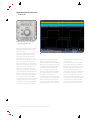
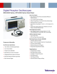
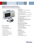
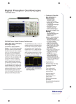
Complimentary Reference Material
This PDF has been made available as a complimentary service for you to assist in
evaluating this model for your testing requirements.
TMG offers a wide range of test equipment solutions, from renting short to long
term, buying refurbished and purchasing new. Financing options, such as
Financial Rental, and Leasing are also available on application.
TMG will assist if you are unsure whether this model will suit your requirements.
Call TMG if you need to organise repair and/or calibrate your unit.
If you click on the “Click-to-Call” logo below, you can all us for FREE!
TMG Corporate Website
TMG Products Website
Disclaimer:
All trademarks appearing within this PDF are trademarks of their respective owners.
Form 080/01
Digital Phosphor Oscilloscopes
DPO4000 Series
Features & Benefits
1 GHz, 500, 350 MHz
Bandwidth Models
2 and 4 Channel Models
Sample Rates Up to 5 GS/s
on All Channels
10 Megasample Record Length
on All Channels
Wave Inspector Controls Provide
Unprecedented Efficiency in
Waveform Analysis
I2C, SPI, CAN Serial Triggering
and Analysis
10.4 in. (264 mm) XGA Color Display
Small Footprint and Lightweight –
Only 5.4 in. (137 mm) Deep and
11 lbs. (5 kg)
USB and CompactFlash on Front
Panel for Quick and Easy Storage
Built-in Ethernet Port
DPO4000 Series Digital Phosphor Oscilloscopes:
Debug Smarter, Not Harder!
Wave Inspector Controls
Imagine trying to efficiently use the
Internet if search engines such as Google
and Yahoo didn’t exist, Web browser
features such as Favorites and Links
didn’t exist or Internet Service Providers
like AOL or MSN weren’t around. Now
you know how most modern oscilloscope
users feel when trying to actually use the
long record length in their digital oscilloscope. Record length, one of the key
specifications of an oscilloscope, is the
number of samples it can digitize and
store in a single acquisition. The longer
the record length, the longer the time
window you can capture with high resolution (high sample rate). The first digital
oscilloscopes could capture and store
only 500 points which made it very
difficult to acquire all relevant information
around the event being investigated. Over
the years, oscilloscope vendors have
provided longer and longer record lengths
to meet market demands for long capture
windows with high resolution to the point
that most mid-range oscilloscopes either
come standard with, or can be optionally
upgraded to, multi-mega-point record
lengths. These mega-point record lengths
often represent thousands of screens
worth of signal activity. While standard
record lengths have increased greatly
over the years and can now satisfy the
vast majority of applications in the marketplace, tools for effectively and efficiently
viewing, navigating and analyzing long
record length acquisitions have been
sorely neglected until now. The DPO4000
Plug ‘n’ Play Connectivity and
Analysis Software Solutions
USB 2.0 Device Port for Direct
PC Control of Oscilloscope
Using USBTMC
Suite of Advanced Triggers
e*Scope® Remote Viewing
and Control
Interoperability with Tektronix
Logic Analyzers
TekVPI™ Probe Interface Supports
Active, Differential and Current
Probes for Automatic Scaling
and Units
Applications
Embedded Design and Debug
Investigation of Transient
Phenomena
Power Measurements
Video Design and Debug
Spectral Analysis
Automotive Electronics Design
and Debug
Manufacturing Test and
Quality Control
Electro-mechanical Design
and Analysis
Bio-medical Product Development
Industrial Control
Digital Phosphor Oscilloscopes
DPO4000 Series
Wave Inspector Controls provide unprecedented efficiency in viewing, navigating
and analyzing waveform data.
Series redefines expectations for working
with long record lengths with the following
innovative new Wave Inspector controls
(above and center):
Zoom/Pan – A dedicated, two-tier frontpanel knob provides intuitive control of
both zooming and panning. The inner
knob adjusts the zoom factor (or zoom
scale); turning it clockwise activates zoom
and goes to progressively higher zoom
factors, while turning it counter-clockwise
results in lower zoom factors and eventually
turning zoom off. The outer knob pans
the zoom box across the waveform to
quickly get to the portion of the waveform
you are interested in. The outer knob also
utilizes force-feedback to determine how
fast to pan on the waveform. The farther
you turn the outer knob, the faster the
zoom box moves. Pan direction is changed
by simply turning the knob the other way.
No longer do you need to navigate through
multiple menus to adjust your zoom view.
2
Setup and Hold search highlighting numerous setup and hold violations in a single acquisition.
Play/Pause – A dedicated play/pause
button on the front panel scrolls the
waveform across the display automatically
while you look for anomalies or an event
of interest. Playback speed and direction
are controlled using the intuitive pan
knob. Once again, turning the knob
further makes the waveform scroll faster
and changing direction is as simple as
turning the knob the other way.
User Marks – See something interesting
on your waveform? Press the Set Mark
button on the front panel to leave one
or more “bookmarks” on the waveform.
Navigating between marks is as simple as
Oscilloscope • www.tektronix.com/oscilloscopes
pressing the Previous and Next buttons
on the front panel.
Search Marks – Don’t want to take the
time to inspect the entire acquisition to
find the event you’re looking for? The
DPO4000 Series features a robust waveform search feature that allows you to
search through your long acquisition based
on user-defined criteria. All occurrences
of the event are highlighted with search
marks and are easily navigated to, using
the front panel Previous and Next buttons.
Search types include edge, pulse width,
runt, logic, setup and hold, rise/fall time
and I2C, SPI and CAN packet content.
Digital Phosphor Oscilloscopes
DPO4000 Series
Serial Triggering and Analysis
One of the most common applications
requiring long record length is serial data
analysis in embedded system design.
Embedded systems are literally everywhere. They can contain many different
types of devices including microprocessors,
microcontrollers, DSPs, RAM, EPROMs,
FPGAs, A/Ds, D/As and I/O. These various
devices have traditionally communicated
with each other and the outside world
using wide parallel buses. Today, however,
more and more embedded systems are
replacing these wide parallel buses with
serial buses due to less board space required, fewer pins, lower power, embedded
clocks, differential signaling for better
noise immunity, and most importantly,
lower cost. In addition, there’s a large
supply of off-the-shelf building block
components from reputable manufacturers,
enabling rapid design development. While
serial buses have a large number of benefits, they also present significant challenges
that their predecessors (parallel buses) did
not face. They make debugging bus and
system problems more difficult, it’s harder
to isolate events of interest and it’s more
difficult to interpret what is displayed on
the oscilloscope screen. The DPO4000
Series addresses these problems and
represents the ultimate tool for engineers
working with low-speed serial buses such
as I2C, SPI and CAN.
Bus Display – Provides a higher level
combined view of the individual signals
(clock, data, chip enable, etc.) that make up
Triggering on specific data packet going across an I2C bus. Yellow waveform is data, blue waveform
is clock. Bus waveform provides decoded packet content including Start, Address, Read/Write, Data,
Missing Ack and Stop.
your bus, making it easy to identify where
packets begin and end and identifying
sub-packet components such as address,
data, identifier, CRC, etc.
Serial Triggering – Trigger on packet
content such as start of packet, specific
addresses, specific data content, unique
identifiers, etc., on popular low-speed
serial interfaces such as I2C, SPI and CAN.
Bus Decoding – Tired of having to visually
inspect the waveform to count clocks,
determine if each bit is a 1 or a 0, combine
bits into bytes and determine the hex
value? Let the oscilloscope do it for you!
Once you’ve set up a bus, the oscilloscope
will decode each packet on the bus, and
display the value in either hex or binary in
the bus waveform.
Packet Decode Table – In addition to
seeing decoded packet data on the bus
waveform itself, you can view all captured
packets in a tabular view much like you
would see on a logic analyzer. Packets
are listed consecutively with columns for
each component (Address, Data, etc.).
Oscilloscope • www.tektronix.com/oscilloscopes
3
Digital Phosphor Oscilloscopes
DPO4000 Series
Search – Serial triggering is very useful for
isolating the event of interest, but once
you’ve captured it and need to analyze
the surrounding data, what do you do?
In the past, users had to manually scroll
through the waveform counting and
converting bits and looking for what
caused the event. With the DPO4000
Series, you can have the oscilloscope
search through the acquired data for
user-defined criteria including serial
packet content. Each occurrence is highlighted by a search mark. Rapid navigation
between marks is as simple as pressing the
Prev and Next buttons on the front panel.
The Performance and Feature Set
You Expect
The DPO4000 Series digital phosphor
oscilloscopes (DPO) deliver the performance
you need to visualize even your most
demanding signals. Bandwidths range
from 350 MHz to 1 GHz, and with all
models offering a minimum of 5x oversampling on all channels and sin(x)/x
interpolation standard, you can be confident
that even the fastest transient events will
be captured and displayed accurately.
The standard 10 M record length on all
channels enables you to capture long
windows of signal activity while maintaining
fine timing resolution.
The DPO4000 Series offers a variety of
analytical solutions including cursors, 25
automatic measurements, statistics and
waveform math. Despite a tiny footprint
(only 5.4" deep) and lightweight (11 lbs.),
the DPO4000 Series offers exceptional
performance, a large 10.4" XGA display
and knob per channel vertical controls.
The new TekVPI™ probe interface sets
the standard for ease of use in probing.
4
Packet decode table showing decoded Identifier, DLC, Data and CRC for every CAN packet in a
long acquisition.
TekVPI probes feature status indicators
and controls, as well as a probe menu
button right on the comp box itself. This
button brings up a probe menu on the
oscilloscope display with all relevant
settings and controls for the probe. The
TekVPI interface utilizes a new probe
power management architecture enabling
direct attachment of current probes
without requiring a separate, bulky power
supply. Finally, TekVPI probes can be
controlled remotely via USB, GPIB or
Ethernet, enabling more versatile
solutions in ATE environments.
The DPO4000 Series delivers an
unprecedented new level of USB plug
‘n’ play operation and PC connectivity.
Acquiring data and measurements from
Oscilloscope • www.tektronix.com/oscilloscopes
Fast waveform capture rate maximizes the
probability of capturing elusive glitches and
other infrequent events.
the instrument is as simple as connecting
a USB cable from the oscilloscope to the
Digital Phosphor Oscilloscopes
DPO4000 Series
OpenChoice® Desktop – Standard software
seamlessly connects the oscilloscope to
a PC.
PC. Provided applications include
National Instruments SignalExpress
Tektronix Edition, OpenChoice® Desktop,
and Microsoft Excel and Word toolbars
enabling fast and easy direct communication with your Windows PC. USB and
CompactFlash ports on the front panel
enable simple transfer of screenshots,
instrument settings, and waveform data
in the palm of your hand.
The unprecedented Wave Inspector
controls, coupled with the DPO4000’s
exceptional performance, comprehensive
feature set, and innovative package
design provide exceptional value.
Other Applications
Video Design and Development
Many video engineers have remained
loyal to analog oscilloscopes, believing
the intensity gradations on an analog
display are the only way to see certain
video waveform details. The DPO4000
Series’ fast waveform capture rate
coupled with its intensity graded view of
the signal provides the same informationrich display as an analog oscilloscope, but
with much more detail and all the benefits
National Instruments SignalExpress Tektronix
Edition – Fully interactive measurement
acquisition and analysis software developed
jointly with NI and optimized for the
DPO4000 Series.
Viewing an NTSC video signal. Notice the
intensity-graded view provided by the DPO’s
ability to represent time, amplitude and
distribution of amplitude over time.
of digital scopes. With up to 1 GHz bandwidth and four inputs, the DPO4000
family provides ample performance for
analog and digital video use.
Digital Design and Debug
The interoperability of the DPO4000 Series
oscilloscope with the Tektronix TLA5000
Series logic analyzer made possible by
Tektronix’ Integrated View (iView™) feature
enables digital designers to solve signal
integrity challenges and effectively debug
and verify their systems more quickly and
easily. The iView feature fully integrates
the industry-leading performance and
measurement accuracy of a Tektronix
oscilloscope with the multi-channel and
powerful triggering capabilities of a
Tektronix logic analyzer. This integration
allows designers to view time-correlated
digital and analog data in the same display
window, and isolate analog characteristics
of digital signals that are causing failures
in their systems. The iView Wizard feature
simplifies this integration of the oscillo-
Tektronix’ Integrated View feature (iView)
fully integrates the performance and measurement accuracy of a Tektronix oscilloscope with the multi-channel and powerful
triggering capabilities of a Tektronix logic
analyzer in one display, allowing designers
to quickly verify and debug their designs.
scope and logic analyzer by guiding the
user through set up and connection. No
user calibration is required. And, once set
up, the iView feature is completely automated. The result – an integrated tool set
for digital design and troubleshooting.
Oscilloscope • www.tektronix.com/oscilloscopes
5
Digital Phosphor Oscilloscopes
Digital Phosphor Oscilloscopes
DPO4000 Series
DPO4000 Series
3
1
2
5
7
1 Zoom/Pan – Dedicated front panel controls for
zooming and panning. The inner knob controls
zoom factor while the outer ring adjust pans the
zoom box across the waveform. Navigating your
waveform has never been easier.
2 Marks – Want to mark your waveform for future
reference or for quick navigation between events
of interest? Simply press the Set Mark button to
place “bookmarks” on your waveform. Use the <--and ---> buttons to navigate through user marks
and search generated marks.
3 Search – Tired of turning the horizontal position
knob endlessly on your current scope to find the
event you’re looking for? Use the DPO4000’s powerful Search feature to find and mark all occurrences of an event based on user specified criteria.
Search types include edge, pulse width, runt, logic,
setup and hold, rise/fall time, and I2C, SPI, and
CAN packet content.
6
6
4 Serial Buses – Trigger on packet level content,
view acquired data as a bus with all packets
decoded into hex or binary, search through acquisitions for specific packet content and even view
all packets decoded in a tabular format, much like
you would see on a logic analyzer. Serial standards
supported include I2C, SPI and CAN.
Oscilloscope • www.tektronix.com/oscilloscopes
5 Stunning Display – The DPO4000 Series
boasts the largest and highest resolution display of
any scope in its class at 10.4" (264 mm) and
1,024x768 resolution (XGA).
4
6 Mass Storage – Use the front panel USB and
CompactFlash ports for simple and convenient
storage of screenshots, waveform data, and oscilloscope setups. Two more USB host ports are available on the rear panel for peripheral connections
as well as a USB device port for instrument control
using USBTMC.
8
Only 5.4" Deep! – Despite the impressive
performance, huge display, and knob-per-channel
controls, the DPO4000 Series is only 5.4" deep,
saving you valuable space on your test bench.
7 Vertical Controls – Knob-per-channel vertical
controls provide simple and intuitive operation. No
longer do you need to share one set of vertical
controls across all four channels!
8 TekVPI™ – New TekVPI probe interface provides
for direct connect current probes, intuitive comp
box controls, remote control of probe settings and
smarter communication between the oscilloscope
and the probe.
Oscilloscope • www.tektronix.com/oscilloscopes
7
Digital Phosphor Oscilloscopes
DPO4000 Series
Characteristics
Vertical System
Input Channels
Analog Bandwidth (–3 dB)
5 mV/div to 1 V/div
Calculated Rise Time
5 mV/div (Typical)
Hardware Bandwidth Limits
Input Coupling
Input Impedance
Input Sensitivity, 1 MΩ
Input Sensitivity, 50 Ω
Vertical Resolution
Max Input Voltage, 1 MΩ
Max Input Voltage, 50 Ω
DC Gain Accuracy
Offset Range
DPO4032
DPO4034
DPO4054
DPO4104
2
350 MHz
4
350 MHz
4
500 MHz
4
1 GHz
1 ns
1 ns
700 ps
350 ps
20 MHz or 250 MHz
AC, DC, GND
1 MΩ ±1%, 50 Ω ±1%
1 mV/div to 10 V/div
1 mV/div to 1 V/div
8 bits
250 VRMS with peaks ≤±400 V
5 VRMS with peaks ≤±20 V
±1.5% with offset set to 0 V
1 mV/div to 50 mV/div ±1 V
50.5 mV/div to 99.5 mV/div ±0.5 V
100 mV/div to 500 mV/div ±10 V
505 mV/div to 995 mV/div ±5 V
1 V/div to 5 V/div ±100 V
5.05 V/div to 10 V/div ±50 V
≥100:1 at ≤100 MHz and ≥30:1 at >100 MHz up to the rated bandwidth
Channel-to-Channel Isolation
(Any Two Channels at Equal
Vertical Scale)
Horizontal System
Maximum Sample Rate
(all channels)
DPO4032
DPO4034
DPO4054
DPO4104
2.5 GS/s
2.5 GS/s
2.5 GS/s
5 GS/s
4 ms
2 ms
Maximum Record Length
(all channels)
Maximum Duration at Highest
Sample Rate (all channels)
Timebase Range (s/div)
10 M points
4 ms
4 ms
1 ns to 1,000 s
Timebase Delay Time Range
–10 divisions to 50 s
Channel-to-channel Deskew Range
±100 ns
Long Term Sample Rate and
Delay Time Accuracy
Delta Time Measurement Accuracy
8
400 ps to 1,000 s
±5 ppm over any ≥1 ms interval
±(1/sample rate + 5 ppm x |Reading| + 0.4 ns)
Oscilloscope • www.tektronix.com/oscilloscopes
Digital Phosphor Oscilloscopes
DPO4000 Series
Trigger System
Main Trigger Modes – Auto, Normal and Single.
Trigger Coupling – DC, HF reject (attenuates
>50 kHz), LF reject (attenuates <50 kHz), noise
reject (reduces sensitivity).
Trigger Holdoff Range – 2 ns to 8 s.
Sensitivity
Internal DC Coupled – 0.35 div DC to 50 MHz
increasing to 1 div at rated bandwidth.
External (auxiliary input) –
200 mV from DC to 50 MHz increasing to 500 mV
at 300 MHz.
Trigger Level Range
Any Channel – ±8 divisions from center of screen.
External (auxiliary input) – ±8 V.
Acquisition Modes
Sample – Acquire sampled values.
Peak Detect – Captures narrow glitches at all realtime sampling rates.
Averaging – From 2 to 128 waveforms included
in average.
Envelope – Min-max envelope reflecting Peak
Detect data over multiple acquisitions.
Hi-Res – Real-time boxcar averaging reduces
random noise and increases resolution.
Roll – Scrolls waveforms right to left across screen
at sweep speeds slower than or equal to 40 ms/div.
Trigger Modes
Edge – Positive or negative slope on any channel or
front panel auxiliary input. Coupling includes DC, HF
reject, LF reject and noise reject.
Pulse Width – Trigger on width of positive or negative pulse that are >, <, = or ≠ a specified period
of time.
Runt – Trigger on a pulse that crosses one
threshold but fails to cross a second threshold
before crossing the first again.
Logic – Trigger when any logical pattern of channels
goes false or stays true for specified period of time.
Any input can be used as a clock to look for the
pattern on a clock edge. Pattern (AND, OR, NAND,
NOR) specified for four input channels defined as
High, Low or Don’t Care.
Setup and Hold – Trigger on violations of both
setup time and hold time between clock and data
present on any two input channels.
Rise/Fall Time – Trigger on pulse edge rates that
are faster or slower than specified. Slope may be
positive, negative or either.
Video – Trigger on all lines, odd, even or all fields on
NTSC, PAL and SECAM video signals.
I2C (Optional) – Trigger on Start, Repeated Start,
Stop, Missing ACK, Address (7 or 10 bit), Data or
Address and Data on I2C buses up to 3.4 Mb/s.
SPI (Optional) – Trigger on SS, MOSI, MISO or
MOSI and MISO on SPI buses up to 10.0 Mb/s (4
channel models only).
CAN (Optional) – Trigger on Start of Frame, Frame
Type (data, remote, error, overload), Identifier (standard or extended), Data, Identifier and Data, End of
Frame or Missing ACK on CAN signals up to 1 Mb/s.
Data can be further specified to trigger on ≤, <, =,
>, ≥ or ≠ a specific data value. User adjustable
sample point is set to 80% by default.
Trigger Delay by Time – 2 ns to 8 s.
Trigger Delay by Events – 1 to 9,999,999 events.
Waveform Measurements
Cursors – Waveform and Screen.
Automatic Measurements – 25, of which up to 4
can be displayed on screen at any one time.
Measurements include Period, Frequency, Delay,
Rise Time, Fall Time, Positive Duty Cycle, Negative
Duty Cycle, Positive Pulse Width, Negative Pulse
Width, Burst Width, Phase, Positive Overshoot,
Negative Overshoot, Peak to Peak, Amplitude, High,
Low, Max, Min, Mean, Cycle Mean, RMS, Cycle
RMS, Area and Cycle Area.
Measurement Statistics – Mean, Min, Max,
Standard Deviation.
Reference Levels – User definable reference levels
for automatic measurements can be specified in
either percent or units.
Gating – Isolate the specific occurrence within an
acquisition to take measurements on, using either
the screen or waveform cursors.
Waveform Math
Arithmetic – Add, subtract, multiply and
divide waveforms.
Math Functions – Integrate, Differentiate, FFT.
FFT – Spectral magnitude. Set FFT Vertical Scale
to Linear RMS or dBV RMS, and FFT Window to
Rectangular, Hamming, Hanning or Blackman-Harris.
Advanced Math – Define extensive algebraic
expressions including waveforms, math functions,
scalars, up to two user-adjustable variables, and
results of parametric measurements e.g. (Intg(Ch1Mean(Ch1)) x 1.414 x VAR1).
Software
National Instruments SignalExpress Tektronix
Edition – A fully interactive measurement software
environment optimized for the DPO4000 Series
enables you to instantly acquire, generate, analyze,
compare, import and save measurement data and
signals using an intuitive drag-and-drop user interface that does not require any programming.
Standard DPO4000 Series support for acquiring,
controlling, viewing and exporting your live signal
data is permanently available through the software.
Additional signal processing, advanced analysis,
mixed signal, sweeping, limit testing and user-defined
step capabilities are available for a 30-day trial period
and can be activated at any time for a minimal
license fee by contacting National Instruments.
OpenChoice® Desktop – Enables fast and easy
communication between a Windows PC and the
DPO4000 Series via USB or LAN. Transfer and
save settings, waveforms, measurements and
screen images.
IVI Driver – Provides a standard instrument
programming interface for common applications
such as LabVIEW, LabWindows/CVI, Microsoft .NET
and MATLAB.
Oscilloscope • www.tektronix.com/oscilloscopes
9
Digital Phosphor Oscilloscopes
DPO4000 Series
Display Characteristics
Display Type – 10.4" (264 mm) liquid crystal TFT
color display.
Display Resolution – 1,024 horizontal x 768
vertical pixels (XGA).
Waveform Styles – Vectors, Dots, Variable
Persistence, Infinite Persistence.
Physical Characteristics
Benchtop Configuration
Dimensions
mm
Height
Input/Output Ports
Width
CompactFlash Drive – Front panel access
(Type 1).
USB 2.0 Full-speed Host Port – Supports USB
mass storage devices and printers. Two ports available on rear-panel and one on front panel.
USB 2.0 High-speed Device Port – Rear panel
connector allows for control of oscilloscope via
USBTMC or GPIB with a TEK-USB-488.
LAN Port – RJ-45 connector, supports 10/100Base-T.
XGA Video Port – DB-15 female connector, connect
to show the oscilloscope display on an external
monitor or projector.
Auxiliary Input – Front panel BNC connector. Input
Impedance 1 MΩ. Max input 250 VRMS with peaks
≤±400 V.
Probe Compensator Output – Front panel pins.
Amplitude 2.5 V. Frequency 1 kHz.
Trigger Out – Rear-panel BNC connector, provides a
positive polarity pulse when the oscilloscope triggers.
TekLink™ Adapter – Connector provided for future
multi-instrument connectivity.
Kensington Lock – Rear-panel security slot
connects to standard Kensington lock.
Power Source
in.
mm
229
9.0
221
8.7
439
17.3
432
17.0
Depth
137
5.4
114
4.5
Weight
kg
lbs.
kg
lbs.
5
11
9.1
20
9.5
21
-
-
Net
Shipping
General Characteristics
Cooling Clearance – 2 in. (51 mm) required on left
side and rear of instrument.
Environmental
in.
Altitude
Operating – 10,000 feet (3,048 m.).
Non-Operating – 40,000 feet (12,192 m.).
Random Vibration
Operating – 0 ºC to +50 ºC
Non-Operating – –20 ºC to +60 ºC
Operating – 0.31 GRMS from 5 to 500 Hz,
10 minutes each axis, 3 axes, 30 minutes total.
Non-Operating – 2.46 GRMS from 5 to 500 Hz,
10 minutes each axis, 3 axes, 30 minutes total.
Humidity
Regulatory
Operating –
High: 40 ºC to 50 ºC, 10% to 60% RH.
Low: 0 ºC to 40 ºC, 10% to 90% RH.
Non-Operating –
High: 40 ºC to 60 ºC, 5% to 60% RH.
Low: 0 ºC to 40 ºC, 5% to 90% RH.
Electromagnetic Compatibility – 89/336/EEC.
Safety – UL61010-1, Second Edition; CSA61010-1
Second Edition, EN61010-1: 2001; IEC 61010-1:
2001.
Temperature
Power Source Voltage – 100 to 240 V ±10%
Power Source Frequency – 47 to 66 Hz (90 to
264 V), 360 to 440 Hz (100 to 132 V).
Power Consumption – 250 W maximum.
10
Rackmount Configuration
Oscilloscope • www.tektronix.com/oscilloscopes
Digital Phosphor Oscilloscopes
DPO4000 Series
Ordering Information
DPO4000 Series
DPO4032 – 350 MHz, 2.5 GS/s, 10 M record
length, 2-channel digital phosphor oscilloscope.
DPO4034 – 350 MHz, 2.5 GS/s, 10 M record
length, 4-channel digital phosphor oscilloscope.
DPO4054 – 500 MHz, 2.5 GS/s, 10 M record
length, 4-channel digital phosphor oscilloscope.
DPO4104 – 1 GHz, 5 GS/s, 10 M record length,
4-channel digital phosphor oscilloscope.
All models include: One P6139A 500 MHz,
10x Passive Probe per Channel, Front Cover
(200-4908-00), CompactFlash Memory Card;
≥32 MB (156-9413-00), User Manual, Documentation
CD (063-3903-00), OpenChoice® Desktop Software,
National Instruments SignalExpress Tektronix Edition
Software, Calibration Certificate Documenting
Traceability to National Metrology Institute(s) and
ISO9001 Quality System Registration, Power Cord,
Accessory Bag (016-1967-00), Three-year Warranty.
Please specify power plug and manual version
when ordering.
Application Modules
DPO4AUTO – Automotive Serial Triggering and
Analysis Module. Enables triggering on packet level
information on CAN bus as well as analytical tools
such as digital views of the signal, bus views,
packet decoding, search tools and packet decode
tables with timestamp information.
DPO4EMBD – Embedded Serial Triggering and
Analysis Module. Enables triggering on packet level
information on I2C and SPI buses as well as analytical
tools such as digital views of the signal, bus views,
packet decoding, search tools and packet decode
tables with timestamp information. SPI is available
on four-channel models only.
Instrument Options
Power Plug Options
Opt. A0 – North America.
Opt. A1 – Universal Euro.
Opt. A2 – United Kingdom.
Opt. A3 – Australia.
Opt. A5 – Switzerland.
Opt. A6 – Japan.
Opt. A10 – China.
Opt. A11 – India.
Opt. A99 – No Power Cord or AC Adapter.
Language Options*1
Opt. L0 – English Manual.
Opt. L1 – French Manual.
Opt. L2 – Italian Manual.
Opt. L3 – German Manual.
Opt. L4 – Spanish Manual.
Opt. L5 – Japanese Manual.
Opt. L6 – Portuguese Manual.
Opt. L7 – Simplified Chinese Manual.
Opt. L8 – Standard Chinese Manual.
Opt. L9 – Korean Manual.
Opt. L10 – Russian Manual.
Opt. L99 – No Manual.
Recommended Probes
TAP1500 – 1.5 GHz TekVPI™ active probe.
TCP0030– 120 MHz TekVPI 30 Ampere AC/DC
current probe.
TCPA300/400*2 – Current measurement systems.
P6246*2 – 400 MHz differential probe.
P6247*2 – 1.0 GHz differential probe.
P5205*2 – 1.3 kV, 100 MHz high-voltage
differential probe.
P5210*2 – 5.6 kV, 50 MHz high-voltage
differential probe.
P5100– 2.5 kV, 100X high-voltage
passive probe.
ADA400A*2 – 100X, 10X, 1X, 0.1X high-gain
differential amplifier.
Recommended Accessories
Service Manual – Order 071-1844-xx (English only).
TPA-BNC – TekVPITM to TekProbe® BNC adapter.
TEK-USB-488 – GPIB to USB adapter.
CompactFlash to USB Memory Card Reader
– Order 119-6827-00.
Soft Transit Case – Order AC4000.
Hard Transit Case – Order HCTEK4321 (requires
AC4000).
Rackmount Kit – Order RM4000.
AMT75*2 – 1 GHz, 75 Ω adapter.
Warranty
Service Options
Opt. C3 – Calibration Service 3 Years.
Opt. C5 – Calibration Service 5 Years.
Opt. CA1 – Provides a single calibration event or
coverage for the designated calibration interval,
whichever comes first.
Opt. D1 – Calibration Data Report.
Opt. D3 – Calibration Data Report 3 Years
(with Option C3).
Opt. D5 – Calibration Data Report 5 Years
(with Option C5).
Opt. R5 – Repair Service 5 Years (including
warranty).
Three year warranty covering all parts and
labor, excluding probes.
*1
Language options include translated front panel overlay for
the selected language(s).
*2
Requires TekVPI to TekProbe BNC adapter
(TPA-BNC).
Oscilloscope • www.tektronix.com/oscilloscopes
11
Digital Phosphor Oscilloscopes
Contact Tektronix:
ASEAN / Australasia / Pakistan (65) 6356 3900
DPO4000 Series
Austria +41 52 675 3777
Balkan, Israel, South Africa and other ISE Countries +41 52 675 3777
Belgium 07 81 60166
Brazil & South America 55 (11) 3741-8360
The Tektronix Customer Service Advantage
Only Tektronix maximizes the lifetime
value of your Tektronix instrument
Canada 1 (800) 661-5625
Central East Europe, Ukraine and the Baltics +41 52 675 3777
Central Europe & Greece +41 52 675 3777
Denmark +45 80 88 1401
Trust Tektronix to offer unequalled engineering expertise and a customer-centric
approach to make managing your service simple. Calibration and Repair Service
Coverage is backed by the highest guarantee of quality assurance in the industry.
You can feel confident that you have received the very best service and repair
for your products. All inclusive, service from Tektronix keeps you up-to-date by
including applicable software updates and safety and reliability modifications.
Choose from flexible service plans, including on-site service.*
Finland +41 52 675 3777
France & North Africa +33 (0) 1 69 86 81 81
Germany +49 (221) 94 77 400
Hong Kong (852) 2585-6688
India (91) 80-22275577
Italy +39 (02) 25086 1
Japan 81 (3) 6714-3010
Find out more at www.tektronix.com/serviceandsupport.
Luxembourg +44 (0) 1344 392400
*Dependent on location and instrument.
Mexico, Central America & Caribbean 52 (55) 56666-333
Middle East, Asia and North Africa +41 52 675 3777
The Netherlands 090 02 021797
Norway 800 16098
People’s Republic of China 86 (10) 6235 1230
Poland +41 52 675 3777
Portugal 80 08 12370
Republic of Korea 82 (2) 528-5299
Russia & CIS 7 095 775 1064
South Africa +27 11 254 8360
Spain (+34) 901 988 054
Sweden 020 08 80371
Switzerland +41 52 675 3777
Taiwan 886 (2) 2722-9622
United Kingdom & Eire +44 (0) 1344 392400
USA 1 (800) 426-2200
For other areas contact Tektronix, Inc. at: 1 (503) 627-7111
Updated 15 June 2005
Our most up-to-date product information is available at:
www.tektronix.com
Product(s) are manufactured
in ISO registered facilities.
Copyright © 2005, Tektronix, Inc. All rights reserved. Tektronix products are
covered by U.S. and foreign patents, issued and pending. Information in this publication supersedes that in all previously published material. Specification and price
change privileges reserved. TEKTRONIX and TEK are registered trademarks of
Tektronix, Inc. All other trade names referenced are the service marks, trademarks or registered trademarks of their respective companies.
11/05
HB/WWW
48W-19032-1