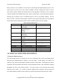
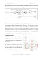
1
University of Detroit Mercy College of Engineering and Science Electrical & Computer Engineering Department Mechanical Engineering Department Detroit, Michigan EE Design (EE 401-403)/Prototype ME 493 Date of Submission: August 12, 2005 Electrical Engineers: Ryan Davis Reta Elias Ono Okagbare Chris Scott Leonard Tomaj Josh Vetter Mechanical Engineers: Chris Collins Brian Cook Jean Harris Edgar Mabson Faculty Advisors: Dr. Mohan Krishnan, Professor of Electrical Engineering Dr. Sandra Yost, Associate Professor of Electrical Engineering Dr. Nassif Rayess, Assistant Professor of Mechanical Engineering Grad Students: Bryan Grider Lei Wang University of Detroit Mercy Hephaestus 2005 2005 – Hephaestus Final Report Outline Abstract 5 1.0 Introduction 1.1 Problem Statement 1.2 Project Requirements (IGVC Rules) 1.3 Performance Specification 5 5 6 8 2.0 Design Planning/Team Organization 2.1 2003/2004 Team Development 2.2 2004/2005 Team Development 12 12 12 3.0 Vehicle & Subsystems Description 3.1 General Vehicle Overview 3.1.1 Vehicle Architecture 3.1.2 Lower Platform 3.1.2.1 Drive Train 3.1.2.2 Wheels 3.1.2.3 Battery Tray Design 3.1.2.4 Motors 3.1.2.4.1 Drive Motor 3.1.2.4.2 Steering Motor 3.1.3 Upper Platform 3.1.3.1 Electronics & layout 3.1.4 Mast 3.1.4.1 Communication between platforms 3.1.4.2 Camera tower 3.1.4.3Wireless router tower 3.1.4.4 E-stop LED Mount 3.1.5 Stability 3.1.5.1 Mass of Vehicle 3.2 Electrical System 3.2.1 Motion Controller 3.2.1.1 Selection Process 3.2.1.2 Roboteq Capabilities 3.2.1.3 Hephaestus Roboteq Configurations 3.2.1.3.1 Serial Control-Run Utility 3.2.1.3.2 Serial Control-Autonomous 3.2.1.3.3 Remote Control 3.2.2 Steering & Drive Encoders 3.2.3 E-stop 3.2.3.1 Manual E-stop 3.2.3.2 Wireless E-stop 3.2.3.3 Audio E-stop 13 14 15 15 16 17 18 18 18 19 20 20 22 23 23 23 24 24 25 25 25 25 26 26 27 29 31 32 32 32 33 34 1 Copyright 2005 University of Detroit Mercy Hephaestus University of Detroit Mercy 3.2.3.3.1 Problems 3.2.3.3.2 Suggestions/Recommendations 3.2.4 Electrical Box 3.2.5 Power System 3.2.5.1 Lower Power Distribution 3.2.5.2 Upper Power Distribution 3.2.5.3 Battery Life 3.2.6 Computers 3.2.6.1 Image Processing Computer 3.2.6.2 Navigation & Control Computer 3.3 Sensory System & software 3.3.1 Vision System 3.3.1.1 Camera 3.3.1.2 Image Processing Software 3.3.2 LADAR System 3.3.3 Navigation Strategy – Autonomous Challenge 3.3.3.1 Algorithm Diagram 3.3.4 Obstacle Detection 3.3.5 Speed/Steering Control 3.3.6 Diagnostic software 3.3.6.1 Encoder Readings 3.3.6.2 Current readings 3.3.6.3 Battery Voltage Readings 3.3.7 Data Logging 3.3.8 Turn Counter 3.3.9 Navigation-GPS Hephaestus 2005 37 38 38 42 43 44 44 45 46 46 47 47 47 48 49 50 50 52 53 56 57 58 59 60 61 62 4.0 Operation & Maintenance 4.1 Startup manual 4.1.1 Rs232 Roborun 4.1.2 Matlab (autonomous) 4.1.3 Remote Control 4.2 Maintenance 4.2.1 Battery Removal & charging 4.2.1.1 Lower Batteries 4.2.1.2 Upper Batteries 4.2.2 LADAR Swap 4.2.3 Reloading Code 4.2.4 Replacement of Parts 4.2.4.1 Encoder Replacement 4.2.4.2 Circuit Repair 4.2.4.3 Chain, Sprocket, Motors 63 63 63 64 64 65 65 65 66 66 67 67 67 68 69 5.0 Critical Evaluation of Design 72 6.0 Component Cost & Info 72 2 Copyright 2005 University of Detroit Mercy Hephaestus University of Detroit Mercy 7.0 Conclusion Hephaestus 2005 72 APPENDICES Appendix A – Manuals 1-Roboteq Manual 2-Roboteq Quick Start Manual 3-LADAR Manual Appendix B – Spec Sheets 1-DeWalt Drive Motor Spec Sheet 2-AME Steering Motor Spec Sheet 3-CUI Optical Encoders Spec Sheet 4-Camera Spec Sheet 5-Wheels Appendix C – Software 1-Overall Simulink File 2-Image Processing Algorithm Simulink File 2M-Image Processing Algorithm m files 3-LADAR Simulink File 3M-LADAR m File 4-Navigation Algorithm Simulink file 4M-Navigation Algorithm m files 5-Speed/Steering Control Algorithm Simulink files 5M-Speed/Steering Control Algorithm m files 6-Obstacle detection LED Display Simulink files 6-Obstacle detection LED Display m files 7-Diagnostic Simulink file 7M-Diagnostic m files 8-Data Logging files 9:1-Encoder_Counter m file 9:2- Angle Counter Simulink File 9M-Angle Counter m File 10- Data Link files 3 Copyright 2005 University of Detroit Mercy Hephaestus University of Detroit Mercy Hephaestus 2005 Appendix D – Other 1-Gantt Chart 2-Failure Mode Effects Analysis 3-Contact Information Appendix E – Reports/Presentations 2004 Hephaestus Report 2005 IGVC Report 2005 IGVC Presentation Appendix F – Website Appendix G – Photos Appendix H– Schematics 4 Copyright 2005 University of Detroit Mercy Hephaestus University of Detroit Mercy Hephaestus 2005 2005 Hephaestus Design Report ABSTRACT The following document serves to detail the conceptual, design, and physical work completed on the University of Detroit Mercy Hephaestus vehicle platform. Hephaestus has served as the platform for a multi-year, multi-discipline effort to compete in the Intelligent Ground Vehicle Competition. This vehicle was created in 2004, including initial design and partial construction. During the past two term of the 2005 school year, the design and construction have been refined and reworked. Additionally, the control and sensory systems have been implemented. It is expected that another multi-disciplinary team will continue work on Hephaestus during the 2006 terms. This team shall remedy the issues mentioned in this document, and prepare Hephaestus for competition in the 2006 Intelligent Ground Vehicle Competition. Currently all systems of the vehicle are intact; however several are in need of work to allow for proper operation. Specifically, the greatest downfall of the Hephaestus platform has been the drive train. It is expected that the 2006 team should redesign the drive and steering mechanisms to allow for optimal, omni-directional operation. While Hephaestus was able to perform limited autonomous activity at IGVC, this may no longer be the case when the 2006 team begins initial work. However; the level of work completed in 2005 should ensure that the following team is able to successful prepare the Hephaestus vehicle for the 2006 Intelligent Ground Vehicle Competition. Figure 1- The Hephaestus 1.0 Introduction 1.1 Problem Statement This year marks the second phase of work on the Hephaestus autonomous vehicle platform shown in Figure 1. With the chassis designed and built in the first phase, the goal of this phase is to improve the reliability of the drivetrain and complete the electrical 5 Copyright 2005 University of Detroit Mercy Hephaestus University of Detroit Mercy Hephaestus 2005 systems. In short, the goal for the second phase is to fully complete the vehicle in preparation for entry into the 13th Annual Intelligent Ground Vehicle Competition. The Hephaestus team consists of 12 engineering students, including 2 Masters students. The six EE students are responsible for all of the electrical systems of the vehicle. One of the EE Masters students leads the Image Processing effort, and the other, Navigation. The four ME students have the responsibility of ensuring that the drivetrain functions properly, and that all components are mounted securely. 1.2 Project Requirements (IGVC Rules) The Hephaestus vehicle platform and sensory and control systems have been designed to both comply with the IGVC rules and to produce an advanced autonomous vehicle. As described in the 2005 IGVC Rules, the vehicles must: • Vehicles must be fully autonomous during each heat of the competition. The team may physically, mechanically, or electrically control the vehicle to the starting line; however, once the signal to begin the heat begins, no member of the team may control the vehicle in any manner other than to stop the vehicle and end the heat. • The vehicle must make direct contact with the ground as its means of propulsion. Any part of the vehicle that makes contact with the ground is defined as the vehicle’s mechanical footing. Examples include: o Wheels. o Tracks. o Pods. • The vehicle will be expected to negotiate around an outdoor obstacle course. Figure 2 shows a possible example of a course segment. Obstacles include: 6 Copyright 2005 University of Detroit Mercy Hephaestus University of Detroit Mercy Hephaestus 2005 o Full-size orange and white construction barrels. o Tall orange construction cones o Construction A-Frame barricades o Five-gallon white pails. o Two-inch deep by two-foot diameter potholes. (These may be driven through with a considerable point deduction for each occurrence.) o Boundaries consisting of two three-inch lines painted on the grass and spaced ten feet apart. These may be either white or yellow, with occasional gaps in the lines. (Vehicles may cross a line, resulting in a point deduction, so long as some portion of the vehicle's mechanical footing remains in bounds.) o Figure 2 – Image of construction barrel and paint lines (Image by Team Hephaestus) • The vehicle must be able to negotiate grass, sand, dirt, and a ramp with a maximum 15% grade. The sand may be two to three inches in depth. These conditions may be dry or wet. • The vehicle must travel at a speed of at most 5 mph. 7 Copyright 2005 University of Detroit Mercy Hephaestus University of Detroit Mercy • Hephaestus 2005 For safety purposes, the vehicle requires a wireless emergency stop (E-stop) mechanism and a manual E-stop system. These systems must bring the vehicle to a complete stop within six feet on inclines up to 15%. o The wireless must operate at a minimum of 50 feet away. o The manual must be operated by the depression of a one-inch red button located at the rear of the vehicle between two and four feet from the ground. • The vehicle dimensions are as follows: o Length—between three and nine feet. o Width—between three and five feet. o Height—between zero and six feet (this does not include an antenna). • The vehicle must be capable of negotiating an 5-foot turning radius. • The vehicle may operate on combustible fuel or electric power. All vehicles must be safety inspected on a simulation course. • Each vehicle will be required to carry a 20-pound payload on top. Because this payload may also contain a camera for the judges, its view should be unobstructed. • The vehicle must be operational under conditions of light rain. 1.3 Performance Specification Analysis of vehicles from past IGVC competitions led the team to develop a series of specifications which would ensure that our vehicle had an appropriate design. By identifying the key features of successful vehicles, we were able create unique solutions to the many difficulties of the competition. 8 Copyright 2005 University of Detroit Mercy Hephaestus University of Detroit Mercy Hephaestus 2005 1. Sensory — The sensory system of the vehicle is essential for lane and obstacle detection. As the sensory system’s ability to detect lanes and obstacles increases, the need for vehicle agility decreases. This relationship exists as a result of being forced to move the vehicle more quickly if objects are not detected until they are right next to or in front of the vehicle. Conversely, if obstacles are detected a considerable distance away from the vehicle, it would be able to react in a slower manner while still avoiding the obstacle. 2. Traction — The vehicle must be able to traverse a variety of terrains (grass, sand, ramp, dirt—wet or dry). 3. Turning — The vehicle needs to accurately negotiate the path that is determined by the navigation system. Agility becomes important when sensory systems are less accurate. 4. Stability — The vehicle must be designed with a low center of gravity and a wide wheelbase in order to avoid becoming unstable under any circumstances that may be encountered throughout the course. A possible ramp represents the only portion of the track where the vehicle is not traversing flat ground. There also exists the possibility of the vehicle partially “missing” the ramp, or falling from the ramp in which case stability is crucial to ensure there is minimal damage to the vehicle. 5. Reaction Time — The vehicle must be able to process sensory inputs and make appropriate adjustments in speed and direction rapidly enough so as to ensure safe navigation through the course at an appropriate speed. 9 Copyright 2005 University of Detroit Mercy Hephaestus University of Detroit Mercy Hephaestus 2005 6. Dimensions — The vehicle must have dimensions that allow maneuverability up ramps, through sandpits, and around all obstacles. 7. Battery Life — There must be enough battery capacity to enable the vehicle to complete the entire course. Batteries must be accessible enough to be changed within the fiveminute window between heats. 8. Speed — The competition vehicle must be able to travel fast enough to complete the course within the maximum allotted time. The winner of the competition is the vehicle that completes the course the fastest. Therefore it is desired to go at the maximum speed of 5 mph while still maintaining reliable reaction time. 9. Reverse — In the event that the vehicle drives into a trap, as seen in Figure 3, it must be able to go in reverse if it does not have a 0° turning radius. Figure 3 – Diagram of possible obstacle traps on IGVC course (Image from IGVC.org) 10. Modularity — In the event of failure or damage at the competition, easy exchange of key components within the five-minute window between runs will be crucial. The LADAR 10 Copyright 2005 University of Detroit Mercy Hephaestus University of Detroit Mercy Hephaestus 2005 must be shared with other UDM teams. The mounting system must be designed around this. 11. Mechanical Reliability — Designs that include mechanical systems that are prone to failure must be avoided. 12. Mechanical Manufacturing — Designs that include mechanical components that will be difficult and time consuming to manufacture must be avoided. 13. Ease of control — An intuitive and reliable method of controlling speed and direction should be incorporated in the design of the vehicle. 14. Cost — Due to the fact that this is a budgeted project, the cost of potential designs must be weighed against their functional advantages. 15. Design Ingenuity — The quality and creativity of the design will determine the success in the design competition of the IGVC. Therefore, aesthetics of design will be nearly as important as functionality. Adherence to the Intelligent Ground Vehicle Competition rules and a strict application of these performance specifications will ensure not only successful completion of the first phase of the design, but also in turn will lead to the fulfillment of the goals of this project in its entirety. 11 Copyright 2005 University of Detroit Mercy Hephaestus University of Detroit Mercy Hephaestus 2005 2.0 Design Planning/Team Organization 2.1 2003/2004 Team Development The development of Hephaestus started during the 2003-2004 academic year by a team of mechanical and electrical engineering seniors. Detailed study of the rules, published competitors reports, and previous results were analyzed to determine the design attributes of the “winning” vehicle. This team started the research, and designed and built the mechanical systems, including the frame and drive train. Unfortunately not much time was left to startup with the electrical systems or to test or improve upon the Mechanical parts. The 2004 Hephaestus report is available in Appendix E:1. 2.2 2004/2005 Team Development The 2005 Hephaestus team is interdisciplinary and composed of senior Electrical & Mechanical Engineering students, as well as graduate Electrical Engineers. The team has an elected leader and is advised by three faculty members. The organization chart is displayed in Figure 4 below. Figure 4- Team Organization Chart The 2004-2005 Hephaestus teams’ focus has been on improving the mechanical system, completing the electrical system and software algorithms, and building a competition-ready vehicle. Each person was given a primary task as well as additional minor tasks. The graduate students were primarily responsible for the image processing and navigation systems. A Gantt chart was created and followed in order to maintain a steady schedule and to meet all deadlines. A copy of the Gantt chart can be found in Appendix D:1. 12 Copyright 2005 University of Detroit Mercy Hephaestus University of Detroit Mercy Hephaestus 2005 Many resources were available to aid our team in this design and implementation process. The same resources as well as new ones will be available to aid the coming senior class as well as other future students. Mainly the manuals found in the appendices will help as well as product websites, Matlab and Simulink help menus, books and professors. Also professional engineers did help such as Stematt, who is a Simulink expert as well as our graduate students. The list below in Table 1 indicates which student worked in what system along with their email address incase further help is needed given that the other available resources are not enough. Table 1-System_Contact Person Name Josh Vetter Reta Elias Leonard Tomaj Ryan Davis Chris Scott Ono Okagbara Brian Grider Lei Wang Chris Collins Brian Cook Jean Harris Levar Mabson Major System Task Computers Data Logging Speed/Steering control Diagnostic Software Roboteq Encoders RC Controller Electric Box Power System Roboteq Encoders E-Stop LED software/hardware Camera LADAR Navigation Image Processing ME’s – Drivetrain, Motors ME’s – Catia, Drivetrain, ME’s – Platforms, Drivetrain ME’s– Battery Tray, Drivetrain E-Mail [email protected] [email protected] [email protected] [email protected] [email protected] [email protected] [email protected] [email protected] [email protected] [email protected] [email protected] [email protected] 3.0 VEHICLE & SUBSYSTEMS DESCRIPTION 3.1 General Vehicle Overview The main design features of Hephaestus are its two platforms and its three articulating wheel hubs that turn simultaneously to produce a zero turn radius. In this manner, the vehicle can translate in any direction allowing for absolute freedom of movement. The design of the wheel assemblies will be described in detail later, but the important feature is the mechanical coupling throughout the drive and steering systems. Two gear motors run the driving and steering functions of the vehicle. As a result, a relatively simple motion controller with two input and two output channels could be used to effectively control the speed and direction of the vehicle. 13 Copyright 2005 University of Detroit Mercy Hephaestus University of Detroit Mercy Hephaestus 2005 Hephaestus uses a single color camera and a laser distance sensor to obtain information about its environment. Using this information, image analysis and a fuzzy logic-based navigation strategy are implemented in a Matlab-Simulink environment running on a laptop PC. Using the resultant navigation output, steering & speed commands are executed via a laptop PC controlling the dedicated motion controller. 3.1.1 Vehicle Architecture The chassis of the Hephaestus vehicle shown in Figure 5 is composed of two octagonal shaped platforms with the lower one supporting the mechanical components (i.e. chain and sprocket drive system) and the upper supporting the electrical components (i.e. laptops, power and control boxes). These two platforms are connected via a hollow shaft that also functions as a raceway for wires, which power most of the electrical systems including the camera. The camera is mounted on the highest point of the vehicle mast. The vehicle is supported by three pairs of wheels arranged in a triangular pattern. In each pair of wheels, one is driven by the motor while the other wheel serves to improve stability of the vehicle. The electrical platform is slightly smaller than the mechanical platform. The mechanical platform has a width of 38 in at the shortest section, which complies with the dimension criteria set forth by IGVC. The upper platform, housing most of the electrical systems, is designed to rotate about the center shaft synchronously with the wheel assembly. This allows the vehicle to always face forward, so that the LADAR and camera can detect obstacles and determine the best course for the vehicle to drive through. Figure 5 – Catia 3D Model The platforms are constructed using 30mm x 30mm Bosch aluminum extrusions. The “skin” of the electrical platform was formed out of alumalite. Alumalite is a man-made material consisting of one corrugated sheet of a polymer plastic sandwiched between two sheets of 14 Copyright 2005 University of Detroit Mercy Hephaestus University of Detroit Mercy Hephaestus 2005 aluminum. This material is much stronger and aesthetically more appealing than the sheets of aluminum used prior to the 2005 design. 3.1.2 Lower Platform The drive train components, including the steering and drive motors, are mounted on the lower platform. This platform is supported by a triangular wheel pattern consisting of three wheel “pods”. Figure 6 – Drive Train Configuration 3.1.2.1 Drive Train Two motors are used to control this vehicle. A drive motor controls the speed and a steering motor controls the angular position of the wheels. Figure 6 displays an AutoCAD model of the top view of the lower platform. The drive chain is shown in blue and the steering chain is shown in red. Note that the red chain is wrapped around the center shaft, which causes the upper platform to rotate with the wheels. Refer to the 2004 Hephaestus report (P28-30) in Appendix E:1 for more information on the drive train design. The idea behind the drive train is relatively simple. The idea is to have a single motor drive three different shafts, with a two to one ratio. The three shafts will then drive three other shaft, perpendicular to them, driving the wheels. This is the idea that was used for the setup of the drive system. However, it did not end up quite this simple. The final drive train setup had the motor driving a shaft single shaft through chain. This single shaft was connected to the drive shaft in the three wheel pods via a different chain. There was a two to one ratio between the drive shaft in the pods and the drive shaft that was connected to the motor. Each shaft in the pods, was connected by bevel gears to a shaft perpendicular to the drive shafts. The wheels were then connected to these shafts. There was also a tensioner on the chain in an effort to keep the drive chain from skipping on the gears under acceleration and to dampen chain harmonics. 15 Copyright 2005 University of Detroit Mercy Hephaestus University of Detroit Mercy Hephaestus 2005 The pre-existing design of the chain and sprocket system did not work because it created slack in the chains and never fully engaged each sprocket. To improve upon this design, an idler was removed, the chain was rerouted and a chain tensioner was added. A drive shaft was then put into place to connect the chain to the motor. This drive shaft then drove the chain which drove the rest of the shafts. The ratio from the motor to the drive shaft was 1:1, and the ratio between the drive shaft and the other shafts is 2:1. This reduces the speed to make sure the vehicle will stay within the speed limits required by IGVC officials and also provide more torque to help move the vehicle. 3.1.2.2 Wheels It is important to note that the configuration of the wheels chosen by last year’s team was strongly influenced by the ramp. A plane is defined by three points; therefore, a three-wheeled vehicle will always travel on a plane, even as it begins to climb a ramp. It will always have three points of contact, which keeps it stable at all times. The three wheeled configuration is illustrated in Figure 7. On the contrary, if a four-wheeled (diamond configuration) vehicle were to begin climbing a ramp with only one wheel facing forward, it would force the vehicle to tip to either its left or right wheel in order to reestablish a three points of contact, meaning the vehicle will no longer be stable. Figure 7 – Wheel Configuration In addition to making sure the vehicle is stable by calculating the center of gravity, maximum acceleration and turning rates. Last year’s team added three extra wheels to increase stability even more as depicted by the wheel configuration in Figure 7, where each wheel pod consists of a pair of wheels, one is driven, the other is free-wheeling. As can be seen in Figure 8, the worstcase scenario distance, d, increases when three extra wheels are added to the three-wheel configuration. In doing this, however, the problems that can only come from such a configuration surfaced. Since only three points are required to make a plane the drive wheels 16 Copyright 2005 University of Detroit Mercy Hephaestus University of Detroit Mercy Hephaestus 2005 often were not in contact with the ground surface due to inconsistencies in the surface. In order to resolve this, the idler wheels were lathed so that approximately 0.75” were removed from the diameter of the wheels. This allowed for all three of the drive wheels to be in contact with the ground at all times yet still allowed the idler wheels to provide stability in extreme circumstances when needed. Figure 8 - Three Wheels vs. Six Wheels Figure 9 –Wheel Pod Schematic The steering motor rotates the entire wheel pod assemblies. As seen from Figure 9, the wheel pods have two separate sprockets connected to two separate chain drives. The top sprocket connects the drive motor to the vertical drive shaft which in turn drives the wheel through a bevel gear. The bottom sprocket connects to the steering motor and in effect serves to turn the entire wheel pod, thus orienting the wheels in the direction of motion. 3.1.2.3 Battery Tray Design The battery tray shown in Figure 10 is designed to hold two 12v car batteries connected in series. It is also required to be housed below the lower platform in order to help lower the center of gravity of the vehicle and must be able to be quickly removed and changed. It also must be in contact with two electrical leads that would allow them to provide power to the vehicle. The dimensions of the battery tray itself although being large enough to contain the two batteries, is small enough to keep the tray from interfering with the motion of the wheel pods and to ensure that it remains clear of any protrusions from the ground that would hinder or possibly stop the vehicle. Figure 10 –Battery Tray 17 Copyright 2005 University of Detroit Mercy Hephaestus University of Detroit Mercy Hephaestus 2005 For quick removal and exchange, drawer sliders were initially used to slide the tray under the vehicle into contact with the electrical leads. However, there was some question regarding the strength and durability of such a system so a new one was implemented. Nylon channels were cut and bolted into the frame of the vehicle to provide tracks for on which the battery tray can slide unto. These were reinforced by steel in order to ensure the strength of the system. After this system was perfected it greatly reduced the time required to change battery trays and made use of the tray and lead system already in place. A locking mechanism was also required to ensure that the tray would not accidentally slide out of contact with the electrical leads or fall off of the vehicle. In order to resolve this difficulty, two holes were drilled into the handle of the battery tray. When the battery tray was properly in place, these two holes lined up with matching holes on the outer frame of the vehicle. This allowed for two bolts to be slid into place and wing nuts could be tightened in order to ensure that they did not move. 3.1.2.4 Motors The motors were selected based on function (gearing, self-locking, etc.) and performance (horsepower, stall torque and RPM). Sufficient power ensures that the vehicle is capable of moving at a speed of 5 mph up the maximum incline of 15%. Stall torque calculations take into account the motor’s ability to propel the vehicle from a stationary position up the incline. Motor RPM is used in conjunction with gearing and wheel size to ensure that the vehicle can achieve the intended speed of 5 mph. Refer to the 2004 Hephaestus report (P21-27) in Appendix E:1 for more information on the selection process. The spec sheets can be found in Appendix B. 3.1.2.4.1 Drive Motor Using the vehicle parameters and requirements, the drive motor selected was the Dustin 2, a modified DeWalt drill motor with the following specifications: 24V, 50.4:1 Gear Ratio, 450 RPM, 0.98 HP and 62.14 Nm Stall Torque. The drive motor proved to provide enough power to climb over obstacles. However, a few problems were encountered with the motor. The biggest problem was with the gears inside the 18 Copyright 2005 University of Detroit Mercy Hephaestus University of Detroit Mercy Hephaestus 2005 drive motor. The motor when driven produced a horrible grinding noise and vibration, along with a very slow rotation. It is not known whether or not the motor came that way from its manufacturer. When the gearbox for the motor was disassembled, it was discovered that the last set of planetary gears were not assembled properly. When the gearbox was reassembled properly, the output shaft spun faster and a lot more smoothly. The next problem that was encountered with the drive motor was the bending of the output shaft. Measures were taken to reduce the bending of the shaft as much as possible such extra support for the shaft. Next, the motor shaft started to rise up. The first attempt to solve this problem was the use of a collar and roller bearings. This did not completely solve the problem and the shaft still bent. To solve this, a longer shaft was used so that the upper supports for the platform kept the shaft from moving up and put a bearing at the top of the shaft to keep it from bending. This solved our motor problems. 3.1.2.4.2 Steering Motor The steering motor was selected based on its ability to turn the wheels. After initial measurements of the necessary torque, a ½ Hp AME 24V right angle motor with a built-in 50:1 worm-gear reducer was chosen. The self-locking feature of the steering motor’s worm gear allows for a mechanical means to maintain wheel direction. A similar self-locking effect in the drive motor allows the vehicle to stay stationary when power is lost or shut off. This acts as a fail-safe mechanism in case of power outage while climbing or descending a ramp. There were a lot of problems with the steering motor. The first thing that was done with the motor was changing how it was mounted. The decision was made to mount it on a thick bracket that is secured on more than one axis unlike the mount from last year. This made sure that the motor wouldn’t move. The next problem was the steering system had too much resistance. The resistance was eliminated by making sure that the main rotating parts were supported by bearing instead of nylon bushings. This helped the whole system turn easier making the steering motor adequate when the system was handled gently. The chain was the weaker part of the steering system. It would have been better if the steering motor had more torque, or there was a higher gear ratio. Something else that would help the steering would be to reduce the amount of weight on the upper platform for it to turn. There were a lot of problems with the motor shaft because of 19 Copyright 2005 University of Detroit Mercy Hephaestus University of Detroit Mercy Hephaestus 2005 its two components. The two components would come unscrewed from each other. To solve this, a hole was drilled through both of the components and a screw was then placed through the holes to hold them in place. This didn’t last very long as the screw was eventually sheared. The next solution was to make the shaft out of one piece. This worked but, because of the amount of tension on the steering chain, the motor output shaft started to bend excessively. To counteract this, a bearing was placed to hold the part of the motor shaft that sticks through the motor mounting bracket. This kept the shaft from bending. However, the fact that the shaft was bent for so long caused excessive wear and stress in the shaft giving it a short life, and causing it to fail at the competition. To make things easier for the steering motor, and to create longer life for the steering motor, either the gear ratio between the motor and the rest of the system needs to be changed, or have a stronger steering motor, or reduce the amount of effort needed to turn the vehicles upper platform and the wheels. Figure 11 – Electrical Component Layout 3.1.3 Upper Platform The upper platform, also known as the electrical platform, houses all the electrical components excluding the Roboteq controller. A layout of these components is displayed in Figure 11. They are: Vision Computer, Control Computer, Power Distribution Box, Batteries, Router, LADAR, and the payload required by the IGVC. This upper platform has been designed in way that it rotates concurrently with the wheels. This means that the LADAR and the camera are always facing the direction in which the vehicle is moving. 3.1.3.1 Electronics & Layout For this year’s group the upper platform was one of the few completely new aspects of the mechanical portion of the vehicle. It was first designed in Catia. Using Catia was a significant help in taking the design through several different changes and variations. The team was able to make sure that it worked and all fit together before actually building it and that saved both time and material, which were in short supply. The final design of the upper platform was very 20 Copyright 2005 University of Detroit Mercy Hephaestus University of Detroit Mercy Hephaestus 2005 functional and visually appealing. The design included a space for the judges’ camera that was covered on all sides except the front. This space for the judges’ camera is linked to the space created for the two computers. The place reserved for the two computers is also covered and flows seamlessly from the judges’ camera compartment. The computer compartment is one of the more unique and interesting aspects of the upper platform. It keeps both laptops stored one above the other. When one wishes to access the computers they each slide out of the compartment on opposite sides. When you slide them out you can use the computers while they are still attached to the platform. This feature allows for quick adjustments while running the vehicle. To keep the vehicle looking forward both the LADAR and the camera are attached to the upper platform. The last part of the upper platform is the mast. It is a basic feature but it is important. The LADAR had to be shared between the two vehicles as it is such an expensive piece of equipment. It needed to be able to be swapped very quickly as there may not be much time between runs of the two vehicles. To accomplish this, the LADAR had to be mounted in the same way on both vehicles. There would not be time to significantly modify how it is attached between runs. On the LADAR are two brackets that connect to two RexRoth 30mm Aluminum pieces. These aluminum pieces hang down vertically. The bracket slides down over them and then they can be fastened in place. This is done with a threaded piece that tightens against the aluminum in a way similar to a set screw. Both vehicles were able to use this method. A swap can be made between the vehicles in just a few seconds. For this vehicle the LADAR had to be attached to the upper platform to keep it facing forward at all times. To keep it low enough the vertical aluminum pieces were hung over the edge of the top platform. This not only lowers it but keeps it out of the way of other components on the top platform. To get a better idea of how the LADAR is mounted please refer to Figure 12. Figure 12 – LADAR Mount 21 Copyright 2005 University of Detroit Mercy Hephaestus University of Detroit Mercy Hephaestus 2005 All the electronic components are integrated to one central unit, the electrical box. The electrical box will be discussed in greater detail later, but here is the electrical box interface which is shown in Figure 13: • It allows the user to alter Roboteq configuration by directly connecting to the electrical box CTRL O DB9 connection o Through this same connection, the control computer drives both motors. • All the useable Roboteq controller pins are routed through the central shaft to the electrical box via Ethernet cable and plugged into the in CTRL I Ethernet slot. • The camera, router, and manual E-Stop are connected to the electrical box in via the Ethernet cable labeled CAMERA, ROUTER, E-STOP • The LADAR is connected to the electrical box through the Ethernet slot labeled LADAR. • The controller computer is connected to the Parallel port labeled LIGHTS I to control the obstacle detection lights. • The DB15 port labeled LIGHTS O connects directly the obstacle light Figure 13 – LADAR Mount 3.1.4 Mast The mast is located in the center of the platform. It rises high above the platform so it can get the best possible view. The mast or shaft of the vehicle not only connects the two platforms together, but serves as a communication pole, a camera tower, wireless router tower and as an EStop LED mount so that it is noticeable for the audience. It was later modified with the addition 22 Copyright 2005 University of Detroit Mercy Hephaestus University of Detroit Mercy Hephaestus 2005 of a cross member which extends its view over the front portion of the upper platform. A picture of this can be seen in Figure 14. 3.1.4.1 Communication Between Platforms The only communication needed between the top and the lower platforms is the connection between the Roboteq controller and the control computer. This connection is made with a retractable Ethernet cable. One end of the cable is connected to the LAN port on the control computer and the other end is spliced and soldered to a 15 pin (db15) serial connector which interfaces with the Roboteq controller. 3.1.4.2 Camera Tower Figure 14 – Mast The camera tower is constructed from the same 30mm x 30mm Bosch aluminum extrusions used for the structure of the upper platform and most of the vehicle. As can been seen in the picture of the picture of the vehicle, the camera mast is mounted on the frame of the computer housing. The camera mast stands between the payload space and the computer housing with a cross bar on the top just below six feet. The cross bar is about two feet in length and is centered on the mast to provide a view free of obstruction from the power box or other components on the upper platform. The camera is attached to the crossbar using a center plastic holder that is screwed to the end of the crossbar. The center plastic and the camera enclosure holder are both taken from a digital camera tripod mount. 3.1.4.3 Wireless Router The two computers are linked together using Ethernet cables. This setup allows for high speed transfer of data between the two onboard computers. Both laptops are equipped with wireless communication capabilities and linked by a linksys 802.11g wireless router, allowing for remote monitoring of the vehicle’s status using an external computer. The wireless router is mounted on top of the pay load space by Velcro tape, and enclosed in a plastic box to shield it from the 23 Copyright 2005 University of Detroit Mercy Hephaestus University of Detroit Mercy Hephaestus 2005 elements. The antenna is mounted on the cross bar of the mast so that a better signal is received. The network setup is described in details later on in this report. 3.1.4.4 E-stop LED Mount The vehicle is equipped with manual and wireless emergency stop options. A pushbutton plunger is located to the rear of the vehicle, on the upper platform. When pressed, the plunger connects the emergency stop pin of the motor controller to ground, cutting power to the motors and halting the vehicle. The same result is achieved by activating the wireless emergency stop via a Bosch automotive Remote Keyless Entry transmitter-receiver unit. Pressing the transmitter causes a relay to connect the same pin to ground. Both the wireless and manual E-stop are connected to an LED display on top of the power box. When the E-stop is enabled the red LED is on and off when the E-stop is disabled. 3.1.5 Stability One of the most important design criteria is to make the vehicle stable. Without stability, the vehicle has no functional guarantee. In the 2004 design, two major calculations were performed to assure stability: center of gravity and incline calculations. The center of gravity was calculated as: y-axis: 0.00” x-axis: 0.96” z-axis: 17.00” The equation used to solve for these values is: (Total Weight )(CGT ) = ∑ (Individual Weight )(Individual CG ) equation 1. where total weight refers to the total weight of the vehicle, CGT refers to the center of gravity of the entire vehicle, individual weight represents the weight of each component on the vehicle and individual CG refers to the lateral location of the center of gravity of each component. Please refer to the 2004 Hephaestus report (P18-20) in Appendix E:1 for more information and calculations. 24 Copyright 2005 University of Detroit Mercy Hephaestus University of Detroit Mercy Hephaestus 2005 Note that the main features of the Hephaestus which improve stability is the three wheel configuration, using two wheels in one wheel pod, and the battery tray being the heaviest item being in the center of the lowest point of the vehicle. Table 2-Weight breakdown 3.1.5.1 Mass of Vehicle The 2004 estimated the vehicle weight would be about 250 lbs; however the final weight of the vehicle is now estimated to be about 355 lbs. Table 2 below will give a breakdown of the weight according to the major big parts of the vehicle. Note that the motors were specked according to a 250 lb vehicle and therefore some of the problems that occurred were due to heavy load. Component Lower Platform Middle Platform Upper Platform Upper Housing Driver Motor /shaft Steering motor IP Laptop Control Laptop LADAR_LMS-200 Camera Miscellaneous electrical components Roboteq controller Upper Batteries (2) Lower Batteries (2) Battery Tray Wheels (6) plus drive train Payload Total Weight Weight 100 6 10 35 3.7 3.9 10 10 10 1 7 4 8.5 84 20 21 20 354.1 3.2 Electrical Sub Systems 3.2.1 Roboteq® DC Motor Controller The Roboteq AX2850 motor controller was chosen to control Hephaestus’s steering and drive motors. The microcomputer-based, X2850 is highly configurable. It is capable of accepting speed and position commands via pulse-width signals from a standard Radio Control receiver, analog voltage commands, or RS-232 commands from a dedicated computer. For more information or help, refer to the Roboteq manual in Appendix A:1. 3.2.1.1 Selection Process The 2004 team’s first option was to use a Motorola HS12 microcontroller to control the robots movement. The problem with using a dedicated microcontroller to control the chosen motors is that power electronics are still needed to amplify the signal to power the motors. Motion controllers, which create their own PWM and have onboard power electronic amplification specific to DC motors, were investigated. After investigating many such controllers, one seemed 25 Copyright 2005 University of Detroit Mercy Hephaestus University of Detroit Mercy Hephaestus 2005 ideal for our project, the Roboteq AX2850. Although it was more expensive than some other controllers, it has functionality that allows for complete autonomous operation. Please refer to the 2004 Hephaestus report (P30-31) in Appendix E:1 for more information on this section. 3.2.1.2 Roboteq Capabilities The following outline is condensed for the AX2580 user’s manual in Appendix A:1. • Fully Digital, Microcontroller-based Design • Multiple Command Modes • Multiple Advanced Motor Control Modes • Automatic Joystick Command Corrections • Special Function Inputs/Outputs • Optical Encoder Inputs • Internal Sensors • Low Power Consumption • High Efficiency Motor Power Outputs • Advanced Safety Features • Data Logging Capabilities • Sturdy and Compact Mechanical Design Some of the special features that apply to this design include serial port inputs, independent motor operation (steering and speed), closed-loop feedback control (in conjunction with optical encoders), emergency stop capabilities and operation information via RS232 commands. 3.2.1.3 Hephaestus Roboteq Configurations The AX2850 can be configured to control the motors by means of an analog joystick, RC joystick, or standard serial commands. It also comes with a PC-based run utility that aids diagnostics and testing. Hephaestus is used in RC mode when being driven manually, while serial port control is the mode implemented using the PC-based utility and during autonomous operation. Please visit the Roboteq website www.roboteq.com to download up to date software and for technical support. 26 Copyright 2005 University of Detroit Mercy Hephaestus University of Detroit Mercy Hephaestus 2005 3.2.1.3.1 Serial Control-Run Utility Although testing and configuration can be accomplished in Matlab, the PC run utility makes it much easier to configure and test the controller. Figure 15 displays the main controls screen. Once the controller is connected to the serial port of the desktop, the controller info should display valid ID, Rev and codes. If nothing happens, try exiting the program and opening it back again. Note that if you actually plan on using this software for testing, the robot should be free standing on jack stands or stools. Note that a regular RS232 cable should be connected directly from the controller to a PC. Figure 15-PC Utility: Controls If testing the controller using this software, make sure the control input is set in RS232 and motor channel A & B as speed separate. This implies that both motors will keep going until manually stopped. If the system is run in closed loop, the encoder feedback is considered. For safety reasons, start with open loop since many problems arose when in closed loop due to problems with the encoder which will be discussed later. Once configurations are set to the desired settings, click to “Save to controller”. Figure 16-PC Utility: Power Settings The next tab shown in Figure 16 enables to set power settings. At first, not much change was done to this configuration, however when testing, we decreased the acceleration at times when the motors seemed to be running too fast and increased it when going too slow. However at the 27 Copyright 2005 University of Detroit Mercy Hephaestus University of Detroit Mercy Hephaestus 2005 final testing, after many testing trials were analyzed, it was determined that the best suitable acceleration according to the specified gains discussed later is 2048. Figure 17-PC Utility: Encoders Many problems seemed to arise from the encoders which will be discussed. This diagnostic software as shown in Figure 17 made it easy to be able to test the encoder readings motors spin. as the Note that the PPR (Pulses per Revolution) of the encoders need to be manually put in each time if correct visual readings are desired. The chosen encoders have a value of 300 PPR. The motor commands can be controlled using the bottom bars. Make sure that as the command is moved in the positive direction, the encoder reading increases positively and vice versa as you move toward the negative direction. More info on the encoders can be found in the Roboteq manual. Figure 18-PC Utility: Run To actually run the motors using this software, go to the Run screen as shown in Figure 18, and click on “Run” in orders to start the motor motion. Command 1 will start the speed motor and command 2 will control the steering motor. Different data could be displayed as specified checking the desired boxes 9. by Data logging is possible using this software, however no attempt was made since data logging was used in Matlab. If for some reason the commands are stopped, however the motors are still operating, disconnect the cable or turn off the controller. 28 Copyright 2005 University of Detroit Mercy Hephaestus University of Detroit Mercy 3.2.1.3.2 Hephaestus 2005 Serial Control-Autonomous As mentioned earlier, configuration can be done in Matlab, but it is easier to do in the Run Utility. For configuring the controller for Autonomous use, it is very important that the motor mode be set “A Speed, B position” since our first motor will be for speed and the second motor is for steering, so that once a desired angle is reached, the motor will stop. Also, since an E-stop system will be in use, make sure to enable it as shown in Figure 19. Note again, that the Roboteq should be in closed loop in order to get the feedback from the encoder module, however because the vehicle was not operating properly and due to the lack of time that was available for testing, the final testing was completed in open loop. Next year’s term should be able to solve this problem. Settings should be saved to controller. Figure 19-PC Utility: Autonomous Settings The closed loop configuration of the proportional gain, integral gain and differential gain shown in Figure 20 is very critical in enabling the robot to move to the desired position. Basic knowledge of controls is needed to be able to find the best suitable settings. Based on the following knowledge, different parameters were configured, tested and observed by moving the steering motor a full turn: Kp gives a fast rise time and when it is too high the system overshoots Kd eliminates overshoot Ki eliminates steady state error, increases response time and rise time The best settings which were determined are as follows which resulted in about a 160° turn: Proportional Gain (Kp) = 0.25 Integral Gain (Ki) = 1.12 Differential gain (Kd) = 7.5 Acceleration = 2048 29 Copyright 2005 University of Detroit Mercy Hephaestus University of Detroit Mercy Hephaestus 2005 Figure 20-PC Utility: Closed Loop Save all settings to the controller and exit from the Roboteq Utility. Now to run the Robot using the control laptop autonomously, connect the serial port going to the upper platform to the controller. Open Matlab and the main Simulink file in Appendix C:1. Run the RS232 initialization commands in Figure 21 and then run the program Figure 21-RS232 Setup % sets up serial interface global R These R = serial('com1'); set(R,'DataBits',7) set(R,'Parity','even') set(R,'Terminator','CR') set(R,'Timeout',1) fopen(R) R %Specify comport used %Set read Timeout in 1 sec %Open comport %Used to display settings %fclose(R) %To close Rs232 commands initialize and open communication to the RS232 connected to the controller. It is important that the correct comport # must be inputted. Note that the PC utility and Matlab cannot share comports. Only one application can use the active comport. If you wish to close the port, then enter the “fclose(R)” command. (NOTE: Serial communication ports settings must be as follows: 9600 bps, 7-bit data, 1 Start bit, 1 Stop bit, Even Parity) Table 3 lists of commands used for autonomous operation via RS232 communication. Most commands were used in the software which will be discussed in a later section. Table 3- Roboteq Commands !Mnn !M ?v or ?V ?a or ?A ?p or ?P ?e or ?E ?i or ?I Set speed or position, where M=motor channel and direction Toggle available digital output lines on/off Query power applied to motors Query amps consumed by motor Query analog inputs Query battery voltages Query digital inputs 30 Copyright 2005 University of Detroit Mercy Hephaestus University of Detroit Mercy Hephaestus 2005 ^mm Read parameter settings, where mm= parameter number ^mm nn Modify parameter, where nn=desired parameter value ^FF Apply parameter changes %rrrrrr Reset controller NOTE: Consult Roboteq User Manual in Appendix A:1 for more detailed descriptions of commands and reply messages. 3.2.1.3.3 Remote Control A radio (Remote) controller (R/C) is used to navigate the vehicle unto the course. The R/C used is an FM Futaba ID#AZPT4VF-72. This controller has 6 channels of communication although the Roboteq controller is cable of handling only three. Since only two channels are required with our vehicle, this R/C controller is more than sufficient for Hephaestus applications. The Roboteq controller has five command control curves for the R/C. They are Logarithmic Strong, Logarithmic Week, Linear, Exponential Week, and Exponential Strong. Figure 22 shows a graph of all the control curves. The linear command curve is a proportional control the control curve chosen for Hephaestus. This proved to be a desired speed increase and decease for the remote control. If the remote control was too sensitive that a slight movement of the toggle stick would cause rapid speed increases then the exponential strong command would be used. Figure 22-Control Curves from Roboteq AX2580 User Manual 31 Copyright 2005 University of Detroit Mercy Hephaestus University of Detroit Mercy Hephaestus 2005 The R/C must be conFigured to the Roboteq controller before it is able to operate in that mode. There are two ways to conFigure the R/D to the Roboteq controller, manually with the push buttons on the controller or using the Roborun software. Details on configuring the controller are provided in the Roboteq manual as well the Hephaestus quick start guide located in Appendix A. 3.2.2 Steering & Drive Encoders The 2004 team chose two optical encoders with quadrature outputs to measure speed and position. Their selection process was based on amperage and pulses per revolution. The Roboteq actually recommends the 200 PPR however the team had a hard time finding the right amperage so as a result two MEH-17 series hollow shaft micro encoders from Microtech Laboratory Inc. were chosen and are connected to the shafts of the steering and drive motors. They provide accurate speed and direction feedback to the controller. These controllers draw 30mA each and have a resolution of 300 pulses per revolution. Refer to the Roboteq manual in Appendix A as well as the spec sheet in Appendix B:3 for any Encoder questions/reference. 3.2.3 E-stop Safety is a major issue in the IGVC competition. There is a chance that vehicles will go off track and possibly hurt someone. The safety features that must be implemented are the manual emergency stop and the wireless emergency stop. On the Hephaestus vehicle, both of these safety features are present. 3.2.3.1 Manual E-stop The controller that is being used on the vehicle has a built in emergency stop pin. When that pin is driven low, then the emergency stop is activated. For the manual e-stop team Hephaestus uses a push-button that acts as a normally open switch. When this button is pressed, pin 15, which is the emergency stop pin on the controller, goes low and the e-stop is activated. The manual configuration is actually connected using an Ethernet connection. This helped us to transmit the data that the e-stop was being pressed to the power box. 32 Copyright 2005 University of Detroit Mercy Hephaestus University of Detroit Mercy Hephaestus 2005 Once the manual e-stop box is opened, it can be seen that the switch has four leads. There are two leads at the top, and two leads at the bottom. The top leads are for a normally closed configuration. The Lower leads are for a normally open switch configuration, which is the configuration that is used in the vehicle. The wires from the Ethernet data cable that were used for e-stop were blue and green stripped. Connecting those wires to the bottom leads of the push button switch allowed for e-stop data to be sent to the power box. A picture of this device is shown in Figure 23 & 24 below. Figure 23-Manual E-Stop Internal Figure 24- Manual E-Stop External 3.2.3.2 Wireless E-Stop As for the wireless E-stop, the team went with a standard Bosch Key fob transmitter and receiver which powers up with a 12 volt source. The wireless e-stop operates at a frequency of 433 MHZ, and has a range of 150 feet. When the lock button on the key fob is pressed, 12 volts is supplied to the receiver which in turn activates the e-stop. To reset the e-stop the lock button is pressed a second time and the controller must be reset. The controller already has a built in pull up resistor configuration, so one did not have to be constructed for the emergency stop to work properly. The proper pin connections for the receiver that were used on the Hephaestus vehicle are in Table 4 below: Pin Connection/Wire Color A-14/Black Wire B-1,B-3/Red Wire C-7/Yellow Wire Function Ground +12 V power supply Activate E-stop Table 4 – E-Stop wiring 33 Copyright 2005 University of Detroit Mercy Hephaestus University of Detroit Mercy Hephaestus 2005 B-1, and B-3 have to be jumped together, with one lead then going to the +12 V power, as seen in Figure 25 below, which is the back panel of the receiver component. Figure 25- RF E-stop pin connections 3.2.3.3 Audio E-stop In previous years there was a threat of the RF e-stop not working because of electromagnetic interference. With this in mind the idea of building an audio emergency stop was thought of. The audio e-stop has 7 blocks, which include an audio amplifier with microphone, a bandpass filter, a full-wave rectifier, an integrator, a comparator, and a latching relay. The sound source that was used is an athletic whistle with a 3.0 kHz frequency. When the sound source is activated, it will go through its various blocks of the whistle stop circuit. The first block of the whistle stop circuit is the audio amplifier. This year the audio amplifier configuration that was used is the Jameco Super Snoop big Ear. This audio amplifier uses various resistor capacitor configurations, a 9V battery, and 2 integrated circuits to provide its functionality. The two integrated circuits that are used are the LM1458, and the LM386N-1. The LM1458 is a general purpose dual operational amplifier, and the Lm386N-1 is a low voltage audio power amplifier. Please refer to the data sheets in Appendix D for more information on these components. The circuit for the audio amplifier is shown in Figure 26. Figure 26-Audio Amplifier 34 Copyright 2005 University of Detroit Mercy Hephaestus University of Detroit Mercy Hephaestus 2005 The output from the audio amplifier goes into the input of the bandpass filter which is the next stage of the audio e-stop circuit. The band pass filter design that was used was the DelyiannisFriend band pass filter circuit. The bandpass filter only allows for the frequency of the sound source used to come through. The other frequencies are not allowed to get through. In order to make the design better in the circuit it is better to +/- .1 kHz from FC to get the upper and lower frequencies. The sound source being used contained a center frequency of 3 kHz. The calculations used to design the bandpass filter are as follows. FC = 3.0 kHz FH = 3.0 kHz+.1kHz = 3.1 kHz FL = 3.0 kHz - .1 kHz = 3.0-.1kHz = 2.9 kHz Bandwidth (B) = FH – FL = 3.1 kHz – 2.9 kHz = .2 kHz kHz Quality Factor (Q) = Fc 3.0kHz = = 15 B .2kHz The resistor values were then calculated using C = 4.7 nF R3 = Q 15 = = 338.8kΩ ≈ 330kΩ π * Fc * C (3.14 * 3.0kHz * 4.7nF ) equation 2. R1 = R3 330kΩ = = 165kΩ ≈ 160kΩ 2 Ho 2 *1 equation 3. R2 = 330kΩ 330kΩ R3 = = = 367Ω 2 4Q − 2 Ho 4(15) − 2 900 − 2 equation 4. 2 Figure 27-Bandpass Filter The circuit of the bandpass is in Figure 27. 35 Copyright 2005 University of Detroit Mercy Hephaestus University of Detroit Mercy Hephaestus 2005 Figure 28 Full Wave Rectifier The next step in the circuit was the full wave rectifier. The full wave rectifier is used to invert all the negative voltage outputs coming from the bandpass filter values. into positive voltage Figure 28 shows the circuit schematic of the full wave rectifier. The integrator circuit comes after the full wave rectifier. The integrator integrates the rectified sinusoid, building up output voltage as long as the applied input voltage is positive. The stronger the input signal, the faster the output voltage will build up, helping to block out ambient noise of the same frequency. A potentiometer should be used in this circuit to vary the sensitivity of the integrator. Figure 29- Integrator Circuit The equation vo = A A was used to find values for R and C. The schematic of the circuit is shown ∴ RC = RC vo in Figure 29. The final circuit to trigger the relay is the comparator circuit is the comparator circuit. Once the integrator is built up to the correct voltage, the output of the comparator will enable the relay 36 Copyright 2005 University of Detroit Mercy Hephaestus University of Detroit Mercy Hephaestus 2005 circuit, which will make the vehicle stop. The reference voltage can be varied using a potentiometer. A voltage divider circuit will have to be set up in order to input the required voltage into the circuit, which in the case of this specific design was 10,3 V, which is shown in Figure 30. Figure 30- Comparator Circuit Figure 25- Relay Circuit The relay latches the circuit which in turn stops the vehicle, when the sound source has been presented. The relay that was used in this design was the Omron G6H Low Signal Latching relay. The relay is shown in Figure 31. 3.2.3.3.1 Problems There were problems presented in this design as there will be within any design. The key is to troubleshoot the problem and come up with a solution that will help to rectify the situation. One problem was that there was a loading effect and negative output from the integrator circuit. This was fixed by designing an inverter circuit, shown in Figure 32. Figure 32- Inverter Circuit for loading and negative output With one solution solved by making an inverter circuit, another problem was presented, which was a loading effect due to 1K input impedance on the actual inverter circuit. This particular problem was solved by using a unity gain buffer at the input of the inverter circuit, shown in Figure 33. 37 Copyright 2005 University of Detroit Mercy Hephaestus University of Detroit Mercy Hephaestus 2005 Figure 33- Unity buffer as input on inverter circuit 3.2.3.3.2 Suggestions/Recommendations The audio e-stop design presented in this documentation is a model for the whistle stop that will be built for next year’s competition. It is a roadmap that the team can use for future whistle stop projects. All of the blocks used here will be used in the whistle stop design, but the components value will vary, and there may be extra things that next year’s team would like to add in order to make the audio e-stop better. A suggestion that was not able to be implemented with this year’s team is getting a DTMF generator for the sound source. This will help to cut out other frequencies better, because there are two distinct frequencies. With this suggestion, there will have to be a dual channel bandpass filter that will have to be designed. 3.2.4 Electrical Box The electric box (power box) controls power to the LADAR, camera, and router. Just as an important feature is that it also integrates all the electrical components to one central unit providing LEDs to indicate system power-up and communication. In simple terms, the electrical box does the following: • Allows the control computer to plug directly into the electrical box via serial data cable o This means that the control computer can directly drive both motors form this connection • It transfers the signal to the Roboteq controller as well as providing an LED to indicate serial data communication. • It provides power for the RC receiver • It provides power for the LADAR • It provides power for the Camera 38 Copyright 2005 University of Detroit Mercy Hephaestus University of Detroit Mercy • Hephaestus 2005 It provides power and connection for the E-Stop o Includes manual and wireless • Provides power for the Wireless router • Interfaces the obstacle light indicators through both a parallel port and a DB15 port Figure 34 below shows a diagram layout of the interior components of the electrical box. Figure 34-Power Box 39 Copyright 2005 University of Detroit Mercy Hephaestus University of Detroit Mercy Hephaestus 2005 Figure 35-R/C Receiver Figure 35 below shows a schematic of the R/C receiver. The R/C receiver is connected to part label 24 and 25 on Figure 34. Figure 36 shows the wiring diagram for both the manual & wireless E-stop system. Figure 36-E-Stop: Manual and wireless 40 Copyright 2005 University of Detroit Mercy Hephaestus University of Detroit Mercy Hephaestus 2005 Figure 37 and Table 5 show the Roboteq controller pins which are converted to an Ethernet connection. These pins are routed through the central shaft via a spiral Ethernet cable and connected to the electrical box. This is done for two reasons. First, the control computer must send signals to the Roboteq controller which is located in the lower platform. The spiral Ethernet cable is used to avoid the cable being stretched and snapped during the upper platform being rotated. They are color coded to match the Ethernet cable. Figure 37 shows the colors of all wires in Ethernet cable. Table 5 shows to what pins or control lines each wire is connected to. Pin 1 2 3 4 5 6 7 8 Wire Color Figure 37 – Ethernet Pins Table 5-Ethernet Connections DB15 to Ethernet converter Pin # 1 Input / Output Output 2 Output 3 Input 4 input 5 6 7 8 9 11 Pwr Out Pwr In Pwr In Input Output Analog In Analog In Signal Output C R/C: RS232 data RS232: Data out Analog: RS232 out R/C: Ch 1 RS232: Data in Analog: Unused R/C: Ch 2 Ana/RS232:Input F Ground Ground +V5 R/C: Ch 3 Output C RC/RS232: Ana In 1 RC/RS232: Ana In 2 12 13 14 Output Pwr Out Pwr Out Output D Ground +5V 15 Input Input E-Stop/Inv 10 Description 2A Accessory Output RS232 Data Logging Output Rs232 Data Out Rs232 Data Logging Output R/C radio Channel 1 Pulses RS232 in (from PC) R/C radio Channel 2 pulses Digital Input F in RS232 mode Controller ground (-) Connect to pin 5 ** Connect to pin 14 ** R/C radio Channel 3 pulses 2A Accessory Output Ch 1 speed or position Ch 2 speed or position Low Current Accessory Output D Controller ground (-) +5V Pwr Output (100ma max) Emergency stop or Invert Switch Input Ethernet pins Wire Color 7 6 5 1 8 3 2 4 41 Copyright 2005 University of Detroit Mercy Hephaestus University of Detroit Mercy Hephaestus 2005 Figure 38 illustrates the diagrams of all four ether net jacks that connect to the electrical box. Figure 38-Ethernet jacks on Electric Box 3.2.5 Power Systems Hephaestus is composed of two completely independent power systems. The first provides power to the motors and controller and is located on the lower platform. The Second provides power to the electronics located on the upper platform. Figure 39 is a schematic for all the component power routing. 42 Copyright 2005 University of Detroit Mercy Hephaestus University of Detroit Mercy Hephaestus 2005 Figure 39– Controller Power Distribution 3.2.5.1 Lower Platform The current draw in the lower platform is more significant, with the two 24V motors drawing a combined 46A during normal operation and a stall current of 120A. The Roboteq power scheme used to route this power to the motors is displayed in Figure 40 (courtesy of www.roboteq.com). To provide the needed voltage and power, two 12V, 55Amp-hour lead acid batteries are connected in series, and are fused and stowed inside the battery tray attached to the bottom of the lower platform. A conservative estimate of the lower platform’s battery life is approximately 1.2 hours as shown in Table 6. Figure 40 – Roboteq Power Distribution 43 Copyright 2005 University of Detroit Mercy Hephaestus University of Detroit Mercy Hephaestus 2005 Current Voltage Lower Platform (Mechanical) (A) (V) Drive Motor Dustin 2 30.46 24 Steering Motor AME 15.5 24 Controller 0.1 12 Encoders 1 (directly from controller 0.03 5 Encoders 2 (directly from controller 0.03 5 R/C Receiver 0.013 5 Total 46.133 75 Table 6-Lower Platform Power Estimation Power (W) 731.04 372 1.2 0.15 0.15 0.065 1104.605 3.2.5.2 Upper Power Distribution With the laptop computers using their internal power sources, the upper platform batteries need only to supply power to the LADAR, camera, and RF receiver. Two 12V, 5 amp-hour batteries are used to provide the estimated maximum power draw of 2.3A and the 24V needed for the LADAR. The upper platform has over 2 hours of run-time battery life as shown in Table 7. Upper (Electrical) Platform Current (A) Voltage (V) Lap top1 6.5 18.5 Lap top2 4.5 18.5 LADAR 1.8 24 Camera 0.085 12 RF E-Stop 0.1 12 Total (Upper Platform) 12.985 85 TOTAL POWER 248.985 Table 7-Upper Platform Power Estimation Power (W) 120.25 83.25 43.2 1.02 1.2 248.92 3.2.5.3 Battery Life As seen in Table 6 and Table 7, the total worst-case power consumption of Hephaestus is 1357W most of which is due to the drive and steering motors. The motors themselves consume 1103W. The rest of the electrical subsystems (2 computers, LADAR, camera, emergency-stop, encoders) consume a total of 254W. Two 12 volt, 55 amp-hour lead acid battery packs are used for the lower platform (mainly the drive and steering motors) to provide a minimum of 71 minutes of run time. In the upper platform, two 12V 5A-hr lead acid batteries are used to power all the electrical subsystems except for the two laptop computers, which will be powered by their own 44 Copyright 2005 University of Detroit Mercy Hephaestus University of Detroit Mercy Hephaestus 2005 independent battery sources. The minimum run time in the upper platform is expected to be 136 minutes. 3.2.6 Computers The Hephaestus control system relies on two laptop computers to insure optimal processing speed. Image Processing, the system bottleneck, runs on a dedicated machine, while all other control algorithms operate on a separate computer. Since the flow of data from the IP computer to the Control computer is of the utmost priority, it operates via a TCP link over a LAN connection. Both computers are physically connected to an onboard router to make the physical connection. Two Simulink models are used to pass the data, and each model has an associated .dll file. These files are included in Appendix C:10, with the following filenames: ¾ ¾ ¾ ¾ Shown below TCPServer.mdl matser.dll TCPClient.mdl matcli.dll in Figure 41 are the two models, conFigured to pass the Image Processing angle from the IP computer to the Control Computer. Figure 41- Data Passing TCPClient.mdl operates on the IP Computer, and the IP ANGLE block should be connected to the output of the IP system. Within the matcli block, the IP address for the destination computer can be set. In the TCPServer model, the matser block should be set with the port corresponding to that of matcli. The Display block will show the current angle, and the output block should be linked to the Navigation system. 45 Copyright 2005 University of Detroit Mercy Hephaestus University of Detroit Mercy Hephaestus 2005 3.2.6.1 Image Processing Computer The Image Processing computer is an HP zx5180us. This has a 2.4 GHz Intel processor, and 1GB of RAM. This laptop also has integrated LAN and WLAN hardware; however, does not include any RS232 ports. To function as the IP computer, these are not needed; however, the Quatech QSP100 PCMCIA Serial Adapter does work with this laptop to provide serial ports. The HP laptop was donated to the Hephaestus Team by Best Buy of Novi, MI. For this reason, all Best Buy logos on the laptop must remain. This laptop also operates Windows XP Professional. From earlier testing, an installation of Linux does remain. The Linux distribution is Red Hat Enterprise v9. Red Hat is available through a prompt during the boot process. While Linux is preferred for its stability and processor priorities, it may not be appropriate for this purpose. There is some evidence available which indicates Matlab is better optimized under Windows, thus negating those advantages. 3.2.6.2 Navigation & Control Computer The Control computer is an IBM ThinkPad A30, with a 2 GHz Intel processor. This system has 768 MB of RAM. This laptop includes integrated LAN and WLAN hardware. Onboard is one single RS232 port, which is insufficient alone for the vehicle communications. A Quatech QSP100 PCMCIA Serial Port Adaptor provides an additional 4 RS232 ports through the IBM's PCMCIA interface. The IBM laptop was passed down to Hephaestus from Dr. Paulik. During the 2005 IGVC Competition, this laptop suffered a fatal error, and required to be restored to factory defaults. The factory default operating system is Windows XP Professional. All work that was done to optimize processes on it were subsequently lost. Because of this problem, it is advisable for hard drive images to be made and stored externally when major changes are made to the computers. Optimization steps include manually setting process priorities, eliminating unused programs, and closing unneeded processes. Much information about Windows XP optimization can be found on the internet. 46 Copyright 2005 University of Detroit Mercy Hephaestus University of Detroit Mercy Hephaestus 2005 3.3 Sensory System & software The Hephaestus sensory system hardware consists of a notebook that interfaces with the navigation sensors via a serial adapter. The serial adapter is a PCMCIA card that provides multiple serial ports to enable the notebook to interface with multiple sensors including the LADAR and motor controller. Hephaestus’ vision algorithm runs on its own dedicated laptop connected to a fire-wire camera. The sensory system on the vehicle is completely housed on the electrical platform. The sensory and vision systems configuration is depicted in Figure 42. All software was completed using a combination of MATLAB® and Simulink® operating under an optimized Windows® operating system. Ethernet Interface PCMCIA Roboteq Controller Fire-wire Camera Figure 42– Sensor and Vision System Integration 3.3.1 Vision System 3.3.1.1 Camera Figure 43 – Camera The camera chosen for the Hephaestus is the Uni-brain Fire-I board camera. This camera was selected for its low cost, low power consumption, and performance. Board Camera shown in Figure The Uni-Brain® Fire-I 43 (courtesy of www.unibrain.com) captures the images used for lane and obstacle detection. This camera is a single board, fully operational Fire Wire color camera, capable of 400Mbps data transmission, with a native resolution of 640x480 pixels and 80.95° horizontal view angle for uncompressed VGA picture acquisition at 30 frames per second. The latest 1394 Texas Instruments® chipsets and Sony® CCD sensor provides a high quality subassembly for image capturing. The camera provides sufficient image clarity and resolution and connects easily to a laptop via the fire wire 47 Copyright 2005 University of Detroit Mercy Hephaestus University of Detroit Mercy Hephaestus 2005 port provided eliminating the need and extra cost of a frame grabber. A plastic weatherproof box was constructed to encase the camera. 3.3.1.2 Image Processing Strategy The image processing strategy determines which obstacles, potholes and lines are present in the camera’s field of view. A preliminary direction is determined by examining an image and establishing a preliminary direction between the lane boundaries. In order to determine this preliminary direction, the captured image is processed in a Matlab® environment. The algorithm, broken down into separate tasks, is outlined in Figure 44. Figure 44 – Flowchart of Image Processing Algorithm First, the image is acquired from the Fire-I camera with YUV color space. Then the color space is transformed to RGB space. After that, adaptive threshold techniques are applied to all three planes and are accompanied by region-based color segmentation. The image in Figure 45b shows the changes made to the image in Figure 45a during the initial color filtering. The binary image in Figure 45b coupled with a Hough transform-based technique detects the existence of the painted lines in the image field. The white pothole is considered a distinct region in the binary image and is detected by an area threshold. As a result, a pothole flag is triggered if the area of the distinct region is bigger than the area threshold. Figure 45a-Course Image before IP Figure 45b-Course Image after IP The purpose of heuristics is to aid in the preliminary direction setting. The strategy is designed with the number of the edges detected and their pixel positions as its main decision-making 48 Copyright 2005 University of Detroit Mercy Hephaestus University of Detroit Mercy Hephaestus 2005 factors. To deal with dashed lane boundaries, the program determines the optimal direction by comparing the current image to the most immediate archived image in which the solid lane line appears, and extrapolates the expected lane from this previous image. Based on heuristics logic, this preliminary direction is set and passed to the navigation software. There are two main programs used to control and interface the image processing procedure which can be found in Appendix C:2. ¾ IP_FW.m ¾ framePocess.m The first IP_FW.m is responsible for communicating with the camera. The code initializes the camera by telling it when to capture an image. It also defines an object where the images are buffered before being processed. Once the buffer has images in it, the latest image is passed to the program called framePocess.m. This program begins by choosing the most recent image from the buffer defined in IP_FW.m. Once through the procedure described above, frameProcess.m generates the desired angle of destination. This angle is then passed back to IP_FW.m. IP_FW.m then passes the angle to a global variable accessible by the navigation algorithm. It is worthwhile to mention that the interaction between the image processing and navigation algorithms is asynchronous. When the angle is passed to the global variable by IP, there is no flag telling the navigation that there is a new angle. The navigation has no way of determining the age of the angle within the variable. 3.3.2 LADAR System The LADAR system used is the SICK® LMS 200. The laser scans horizontally through a 180degree range at 0.5° resolution, for a distance up to about 80m. Refer to the LADAR manual in Appendix A:3 for more information. The measurement information is transmitted via serial communication to the navigation computer. The LMS200Setup.m file sets up the LADAR which can be found in Appendix C:3. For this application, the LADAR is configured so that the farthest distance is approximately 8 m. Using this laser scanner, the width of obstacles and their distance away from the front of the vehicle are determined. 49 Copyright 2005 University of Detroit Mercy Hephaestus University of Detroit Mercy Hephaestus 2005 3.3.3 Navigation Strategy – Autonomous Challenge The purpose of the navigation algorithm is to merge the preliminary direction angle provided by the image-processing algorithm with the obstacle avoidance information obtained from the LADAR system to generate a final direction for the vehicle. The algorithm is implemented in Simulink® using fuzzy inference techniques as shown in Figure 46. Refer to Appendix C:4 for the Navigation controller software. Note that the Navigation is almost identical to that of the Warrior Team since the same person worked on it. Figure 46 – Navigation Algorithm Flow The direction provided by the image-processing computer is the input to a Fuzzy Inference system, whose output is a fuzzy membership function of possible steering directions. The LADAR output, which is a 180º map of obstacle locations in front of the vehicle, is converted to an equivalent fuzzy membership representation. The two sets of membership functions are then fused to produce an overall fuzzy membership function of possible steering directions. This membership function is then “defuzzified” to produce a final steering direction, which is the input to the steering control algorithm. 3.3.3.1 Algorithm Diagram The overall Navigation System Diagram is shown in Figure 47. This System consists of the Image Processing unit, LADAR unit, Navigation Controller, Drive system and light indicators. Each system is broken up into subsystems which will be explained. 50 Copyright 2005 University of Detroit Mercy Hephaestus University of Detroit Mercy Hephaestus 2005 Figure 47: Overall Control Simulink Model Figure 48 is the Navigation Controller Algorithm. The Image Processing input is ran through a saturation block, where it imposes upper and lower bounds of the input. This is then rounded and fuzzified to get possible angles as a direction for the vehicle to drive. Figure 48: Overall Navigation Simulink Model Obstacle Avoidance is implemented using the LADAR to locate obstacle positions. The obstacle avoidance system generates a database of distance values referring to obstacle location ahead of the vehicle. Figure 49, below is the critical remap block of the LADAR data. The minimum input from the LADAR is found and compared to 2000. If the minimum is less than this value 51 Copyright 2005 University of Detroit Mercy Hephaestus University of Detroit Mercy Hephaestus 2005 then the minimum value is subtracted from the original LADAR data. If the value is greater than 2000 then the LADAR data is used as is, with no remapping. Figure 49: Navigation-Critical Remap To create the final angle of travel of the vehicle, the goal following information was combined with the obstacle avoidance information as shown in Figure 48. The two data sets are fused together using the minimum function to produce an overall fuzzy membership function of possible steering directions . This data is then defuzzified using the COLA method. The COLA method finds the largest area of the output membership function and calculates its center. With this method, the center corresponds to the best solution for that system. The defuzzified angle is a crisp angle of travel that is the final angle of travel used by the vehicle. Figure 50- Light switch circuit 3.3.4 Obstacle Detection Obstacle detection is primarily handled by the LADAR range finder. The location of the LADAR mount enables it to pickup a variety of obstacle height. The Hephaestus is equipped with lights to indicate when and where an obstacle has been detected. The lights are placed on the front and sides of the vehicle, and a light is also mounted on the back of the vehicle to mimic the front lights for spectators 52 Copyright 2005 University of Detroit Mercy Hephaestus University of Detroit Mercy Hephaestus 2005 behind the vehicle. The light indicator is setup with a simple switch circuit using two mosfet switches and a 555 timer. The timer circuit is set up with a resistor ratio to produce 3.5Hz frequency. The 555 timer enables the lights to blink at a continuous frequency whenever a light is turned on. Making the lights blink at a controlled frequency make them easily observable. The circuit setup for the lights is illustrated in the following Figure 50. The Simulink program that controls the light is made up of a few Matlab function, switching and logic blocks. The file is then merged into the navigation program and is fed as an input whenever the LADAR transmits information. Please see Appendix C:6 for the software files. 3.3.5 Speed/Steering Control Figure 51 – Steering/Speed Control Flow Chart The purpose of the control software is to be able to command the Roboteq controller to steer the desired angle and to slow down where necessary. The navigation angle is the input for the steering and speed system as shown in Appendix C:1. The flowchart of how the control system operates is shown in Figure 51. The speed control is based on a two-speed strategy. If it is determined by the navigation algorithm that the vehicle is to be turned, the Roboteq controller is commanded to operate in a low-speed mode. High-speed mode is initiated when no turns are required. Note that the Roboteq controller has built-in speed and position control capability, so the steering and speed system have only to generate the appropriate command signals. When an angle is given by the navigation, it is important to now if this angle is a positive or a negative to know what command should be outputted. The following is an example of the commands according to direction: !a Æ will drive the speed motor to drive backwards !A Æ will drive the speed motor to drive frontward 53 Copyright 2005 University of Detroit Mercy Hephaestus University of Detroit Mercy Hephaestus 2005 !b Æ will drive the steering motor to turn to the left direction !B Æ will drive the steering motor to turn to the right direction Note that channel A is connected to the speed motor and since our vehicle is omni directional there is no need for backward speed motion. However the steering motor, channel B is critical and should only move right when given a positive angle. 3.3.5.1 Simulink Block The Simulink block in Figure 52 acts exactly as the discussed flow chart. There are 3 switches to determine if the angle is zero, less than zero or greater than zero. Note that originally this was done using if then blocks which performed ok when running with constant input value. However when connected to the Navigation as the input, it did not work and therefore switches were used instead. If there is no angle (0 value), the vehicle will just drive straight at a high speed, if the angle is positive, slow the vehicle and turn right. If the angle is negative, take absolute value of angle since Matlab cannot handle hex to dec negative conversions, slow the vehicle and turn left. The following is the three m files used: ¾ Rs232Read_Speed.m ¾ Rs232Read_Speed_Pos.m ¾ Rs232Read_Speed_Neg.m Figure 52 – Steering/Speed Control Simulink Block 54 Copyright 2005 University of Detroit Mercy Hephaestus University of Detroit Mercy Hephaestus 2005 The actual input from navigation represents an angle in degrees. However, the Roboteq controller only understands pulse values ranging from 0-127. The following equation helps us achieve the actual value. Degrees * 300 pulses/360 degrees = pulses equation 5 As for the speed, we are only dealing with 2 different speeds, a high speed and a low speed. Remember that the maximum speed allowed for the IGVC competition is 5 mph. The speed can be converted using equations according to the gear ratios and tire diameter, however we ended up using values that gave us the approximate speed. A speed of 30 gave us a low speed. All the software consists of a Simulink file and m files for the control algorithm which can be found in Appendix C:5. Note that the code is very well commented. 3.3.5.2 Control m Files The code in Figure 53 is commented very well and all three m files are very similar. Only one m file will be clearly explained, the Rs232Read_Steer_Pos.m file. When the Navigation angle outputs a positive non zero, this block is simulated. The “u” is the input of this Matlab function which is the angle, function x = Rs232Read_Steer_Pos(u); %Slows down vehicle and turns in the right direction according to input angle global R % Convert numerical representation of Low speed to hex character and send via %serial port to Roboteq Controller along with the specified motor character. wordA = '!A' %Specifies channel A (Speed Motor +) spdA= 30 %# needs to be positive integer if spdA < 16 %Convert dec value to hex speedA = cat(2,'0',dec2hex(spdA)) else speedA = dec2hex(spdA) end command= cat(2,wordA,speedA) %roboteq character format(motorA,speed) if(R.BytesAvailable>0) xx=fread(R,R.BytesAvailable); end fprintf(R,command) %Clear unnecessary data from Rs232 %Send the character out using Rs232 %Convert steering angle to position representation of (0-127) and then to %hex character. send via serial port to Roboteq Controller along with the %specified positive steering motor character. wordB = '!B' %Specifies channel B (Steering Motor +) fprintf(R,'!Q1') %Reset Steering Encoder Counter 2 PDeg=0.8; %300pulses/360 degrees dirBPulse=u*PDeg %Angle * PDeg=desired position (0-127) dirB = round(dirBPulse) %get as integer value if dirB < 16 %Convert to hex SteerB = cat(2,'0',dec2hex(dirB)) else SteerB = dec2hex(dirB) end command = cat(2,wordB,SteerB) %roboteq character format(motorB,speed) if(R.BytesAvailable>0) xx=fread(R,R.BytesAvailable); end fprintf(R,command) %Clear unnecessary data from Rs232 %Send the character out using Rs232 x = [dirB] Figure 53 –M-File: Rs232Read_Steer_Pos 55 Copyright 2005 University of Detroit Mercy Hephaestus University of Detroit Mercy Hephaestus 2005 and “x” is the output, mainly only used for the display. Since the RS232 is throughout, specify this is a global parameter, “R”. Specify which motor/command is addressed. “!A” specifies the speed motor in the positive direction. Convert the desired speed to a hexadecimal value. For this example 30 will be 1E. command=cat(2,wordA,speedA) basically puts the values together as !A1E. The next part of the code basically reads any flawless unnecessary data from the RS232 so that is doesn’t interfere with the messages sent. This part of the code is used throughout all the programs and should be executed before sending the message to the controller via the fprintf command. if(R.BytesAvailable>0) xx=fread(R,R.BytesAvailable); end Now that the speed has been setup, execute the steering commands. “!B” specifies the steering motor in the positive direction. fprintf(R,'!Q1') resets the steering encoder. This was added at the competition in order for the steering to work appropriately and it might interfere with the encoder counter code which will be discussed at a later section. Equation 5 was broken down in order to put the angle in terms of values from 0-127. The rest of the code is a repetition, but this time to get the steering command out to the controller. 3.3.6 Diagnostic software Figure 54 – Diagnostic Simulink Blocks The Roboteq controller commands make it very easy to be able to read data. The Roboteq manual refers to many commands that can be sent for query purposes. Three main data that we are interested in knowing while the software is running are the battery voltage readings, encoder readings, and 56 Copyright 2005 University of Detroit Mercy Hephaestus University of Detroit Mercy Hephaestus 2005 current readings. The m files that correspond to the Simulink file shown in Figure 54 are as follows: ¾ Rs232Read_Current.m ¾ Rs232Read_Current.m ¾ Rs232Read_Voltage.m This is possible by sending a question command to the Roboteq and then reading back what the controller sends back. Note that all the m files discussed are exactly the same aside from the question command and maybe a conversion equation. Please refer to the Simulink file and the commented code in Appendix C:7 for more details on this section. Figure 55- M-File: Rs232Read_Encoder 3.3.6.1 Encoder Readings The M-file for the encoder reading is shown in Figure 55. It is very important to read the speed and position computed by the encoder module. Sending the command ‘?K’ to the controller will ask the question and then 3 characters will be sent back. The first ‘fscanf(R)’ will return the question, the second ‘fscanf(R)’ will return the hexadecimal number speed reading for the first encoder, and the third ‘fscanf(R)’ will return the hexadecimal number position reading for the second encoder. Note that the while loop is there to make sure function [StrngEncdr,SpdEncdr] = Rs232Read_Encoder(u) global R %This mfile sends a question to the encoder module to find out what the %speed reading is. The module will return 3 characters. The question, %encoder 1 reading, & Encoder 2 Reading. The values are signed Hexadecimal %numbers ranging from -127 to +127. x='?k' if(R.BytesAvailable>0) %Clear unnecesary data from Rs232 ifany xx=fread(R,R.BytesAvailable); end fprintf(R,x) test=0 while(test==0) ReadValue=fscanf(R) [n m]=size(ReadValue) %Send Encoder reading Question command %Read 1st sent character (same as sent) if (m>2) %If there is garbage infron, clear it xx=strcat(ReadValue(1,m-2:m-1)) if(min(x==xx)) %If cleared, read next characters ReadValue2=fscanf(R) %Read 2nd Character(Encoder Speed) ReadValue3=fscanf(R) %Read 3nd Character(Encoder position) test=1 %Get out of loop end end end %Speed encoder value reading (-127 to +127) A=cellstr(ReadValue2) %Make Character array cell array SpdEncdr = hex2dec(A) %Convert Hex value to dec %Steering encoder value reading (-127 to +127) B=cellstr(ReadValue3) %Make Character array cell array StrngEncdr = hex2dec(B) %Convert Hex value to dec that all three data points are received and there is no error. pass(1) = [StrngEncdr] pass(2)= [SpdEncdr] 57 Copyright 2005 University of Detroit Mercy Hephaestus University of Detroit Mercy Hephaestus 2005 Matlab doesn’t allow to change the values directly to decimal format. Each character must be converted to a cell array by using the “cellstr” command. Then the character can be converted from hexadecimal to decimal which will give decimal values. Equations maybe added to the m file to convert this value to actual readings. Please refer to the Simulink file and the commented code in Appendix C:7 for more details on this section. 3.3.6.2 Current Readings Figure 56- M-File: Rs232Read_Current To inquiry the controller to return the actual number of Amps being consumed by each motor, the M-file shown in Figure 56 is simulated. The command question is number returned unsigned ‘?A’ The is an Hexadecimal number ranging from 0 to 256 (0to Hexadecimal). FF in Note that everything in this program aside from different variable names and the command question is the same as the previous diagnostic file in such that three characters function [StrMotCur,SpdMotCur] = Rs232Read_Current(u) global R %This query will cause the controller to return the actual number of Amps %being consumedby each motor. The number is an unsigned Hexadecimal %number ranging from 0 to 256 (0to FF in Hexadecimal). if(R.BytesAvailable>0) %Clear unnecesary data from Rs232 xx=fread(R,R.BytesAvailable); end fprintf(R,'?A') %Send current reading Question command test=0 while(test==0) ReadValue=fscanf(R) %Read 1st sent character (same as sent) [n m]=size(ReadValue) if (m>2) %If there is garbage infron, clear it xx=strcat(ReadValue(1,m-2:m-1)) if(min(x==xx)) %If cleared, read next characters ReadValue2=fscanf(R) %Read 2nd Character(Speed Mtr Current) ReadValue3=fscanf(R) %Read 3nd Character(Steer Mtr Current) test=1 %Get out of loop end end end %Speed motor current reading A=cellstr(ReadValue2) StrMotCur = hex2Dec(A) %Make Character array cell array %Convert Hex value to dec %Steering motor current reading B=cellstr(ReadValue3) %Make Character array cell array SpdMotCur = hex2Dec(B) %Convert Hex value to dec are returned, where the first is the questions sent and the pass(1) = [StrMotCur] pass(2) = [SpdMotCur] last two are the speed motor current and the steering motor current respectively 58 Copyright 2005 University of Detroit Mercy Hephaestus University of Detroit Mercy Hephaestus 2005 3.3.6.3 Voltage Readings This ‘?e’ query M-File shown in Figure 57 will cause the controller to return values based on two internally voltages. measured Just as before, the function [MainBattV,InternalVolt] = Rs232Read_Voltage(u) %This codes sends a character to the Roboteq controller to read the main 24v %voltage reading as well as the internal 12v. controller will send back 3 global R characters, the first is the sent if(R.BytesAvailable>0) xx=fread(R,R.BytesAvailable); end x='?e' fprintf(R,x) question, and the next two are voltages. The first voltage is the Main Battery voltage present at the thick red and black wires. The second voltage is the internal 12V supply needed for the controller’s microcomputer and MOSFET values are drivers. The unsigned Hexadecimal numbers ranging from 0 to 255. To convertthese numbers into a voltage Figure, formulas described in “Internal Voltage MonitoringSensors” on page 62 of the Roboteq manual were used. test=0 while(test==0) ReadValue=fscanf(R) [n m]=size(ReadValue) %Clear unnecesary data from Rs232 if %Send Voltage Question command %Read 1st sent character (same as sent) if (m>2) %If there is garbage in front, clear it xx=strcat(ReadValue(1,m-2:m-1)) if(min(x==xx)) %If cleared, read next characters ReadValue2=fscanf(R) %Read 2nd Character(Main Voltage) ReadValue3=fscanf(R) %Read 3nd Character(Internal Voltage) test=1 %Get out of loop end end end %Main Battery Voltage-Should be about 24 V A=cellstr(ReadValue2) %Make Character array cell array %to able conversion MBattV = hex2dec(A) %Convert Hex value to dec MainBattV = (55*MBattV)/256 %Convert dec value to voltage value %Internal Battery Voltage-Should be about 12 V B=cellstr(ReadValue3) %Create Cell array to able conversion IBattV = hex2dec(B) %Convert Hex value to dec InternalVolt =(28.5*IBattV)/256 %Convert dec value to voltage value pass(1) = [MainBattV] pass(2)= [InternalVolt] Figure 57- M-File: Rs232Read_Voltage 59 Copyright 2005 University of Detroit Mercy Hephaestus University of Detroit Mercy Hephaestus 2005 3.3.7 Data Logging The Hephaestus vehicle platform makes use of the onboard wireless router to provide external monitoring and data logging. This is accomplished with the use of two Simulink models shown in Figure 58, and an associated .dll file. This method transmits the data using a User Datagram Protocol (UDP), which is not as reliable as TCP; however, it requires less processor time. The Transmission file operates within the Control computer, and the Receive file runs on the external computer. The files are included in Appendix C:8, under the following names: ¾ DataLogTransmit.mdl ¾ DataLogRecieve.mdl ¾ sfun_time.dll These blocks are highly configurable, and can support any number or type of data streams. To add more channels, simply modify the Input and Output Data Types within the Pack and Unpack blocks. By configuring the UDP Send, and UDP Receive blocks, the data stream can be designated for a single computer, or broadcast to many PCs or laptops. It should be noted, that using the UDP transmission method, and a wireless connection, there will be some amount of lost or corrupted data. The only way to avoid this, is to either use a TCP connection, or a wired connection. TCP is not recommended for this, as it will slow the processing on the control computer. Figure 58-Data Logging Simulink Files 60 Copyright 2005 University of Detroit Mercy Hephaestus University of Detroit Mercy 3.3.8 Turn Counter Hephaestus 2005 Figure 59 – Angle Counter Since the spiral cord in the shaft between the two platforms will loosen and tighten as the vehicle turns, it is critical to keep track of the number of full turns so that pressure is not put on the wiring. This is being taken care of by code in two different ways. Only choose one. At first, a block was added to the Simulink file as shown in Figure 59 where a cumulative sum block keeps track of the angle inputted from Navigation and a Matlab function file will rewind the cord by turning the vehicle once it’s limits have been reached. It is not for sure, but it is believed that this is not valid because the summation box might keep reading the input from navigation before it gets a chance to refresh. Figure 60 – Steering Encoder Counter With that in mind another block was created which calls an m function directly as shown in Figure 60. This Matlab file will be reading the steering encoder counter instead and making judgments on that. Once the encoder counter reaches its specified limits, the vehicle stops and rotates and then the encoder counter is reset. The only problem with this is to make sure that the encoder is not reset anywhere else in the program. It is believed that at the IGVC competition, the encoder was reset each time so that proper actions were taken. 61 Copyright 2005 University of Detroit Mercy Hephaestus University of Detroit Mercy Hephaestus 2005 3.3.9 Navigation-GPS It was intended for the Hephaestus to compete in the navigation challenge in the 2005 IGVC. The electronic hardware that was slated for use for this purpose on the Hephaestus are shown in Figure 61. Figure 61-From Left to right: Accelerometer, compass and GPS unit A Race tech AC-22 accelerometer for measuring linear movement (acceleration) applied to the vehicles inertial frame. A PNI micromag xx compass used to pinpoint the vehicles location and a Rikaline GPS6010 Global Position System unit to provide waypoint locations on the navigation course. The integration of the sensors mentioned above make up the inertial navigation system. Together they can tell the system, the location of the vehicle, measure the change of position (distance), and provide direction. The network of the system is INS susceptible to small errors from all sensors which can add up to make the system unreliable. + To compensate for the errors a Kalman filter is added. Kalman filter uses estimates from previous time steps to predict GPS + the current state (position and velocity), and used measurements of current state to refine prediction of new states. A diagram illustrating the use of the Kalman filter within the navigational system is depicted in Figure Error Modeling + Kalman filter 62. Figure 62: A depiction of the Navigational system 62 Copyright 2005 University of Detroit Mercy Hephaestus University of Detroit Mercy Hephaestus 2005 4.0 Operation & Maintenance This section of the report is very critical in that proper steps are taken in order to initialize the vehicle and have a safe maintenance procedure. Note that safety is most critical and students/faculties should be careful. 4.1 Startup Manual As mentioned earlier, there are three ways to operate Hephaestus. The first is with the Roborun software, the second would be with the speed control software with the programming computer, the third and final way to move Hephaestus is with a remote controller. Note incase of an emergency, the best way to stop the vehicle is to E-Stop it, however in situations where E-Stop is not active turn off the controller. 4.1.1 RS232 Roborun Utility In the PC utility, many of the Roboteq configurations can be set. This program is very useful in configuring, testing and diagnostics. The following are detailed steps in operating the Roboteq controller using its own software run utility. 1. The robot should be free standing on jack stands or tools for this type of testing. 2. Connect the 55A fuse located on the end of the battery tray. 3. Slide the battery tray in the vehicle (located on the lower platform) 4. Connect the Roboteq controller directly to a PC via RS232 serial cable. 5. Launch Roborun software. 6. Turn on the controller 7. Make sure the correct comport is active 8. Once the controller is connected to the active port of the desktop, the controller info should display valid ID, Rev and codes. If nothing happens, try exiting the program and opening it back again. 9. ConFigure the setting to RS232. 10. Setup the motor controller to the desired settings as described in section 3.2.1.3.1. 63 Copyright 2005 University of Detroit Mercy Hephaestus University of Detroit Mercy Hephaestus 2005 NOTE THAT THE E_STOP IS NOT ACTIVE IN THIS COMMUNICATION SETUP SINCE THE ELECTRIC BOX IS NOT CONNECTED TO THE CONTROLLER. 4.1.2 Matlab (autonomous) Note that testing can be done from a desktop PC just as mentioned in the last section where the controller is connected to the PC, but running in Matlab rather than the Roboteq utility. However, in this section, the autonomous startup manual will be discussed where the onboard laptop is doing the controlling. These steps assume that configuration settings mentioned in section 3.2.1.3.2 are all set. 1. Connect all connection to the power box located on the upper platform 2. Connect the 55A fuse located on the end of the battery tray. 3. Slide the battery tray in the vehicle (located on the lower platform) 4. Connect the control computer to the electrical box via RS232 serial cable 5. Turn on the electrical box 6. Turn on the Roboteq Controller 7. Open Matlab and launch the main Simulink file in Appendix C:1. 8. Run the Rs232 initialization commands 9. Run the Main Simulink program 10. To stop this program, either hit the pause, stop button in Matlab, or E-stop the vehicle. 4.1.3 Remote Control The following are instructions to start and operate the vehicle in R/C mode: Fore more information on configuration for this type of operating mode, please refer to section 3.2.1.3.3. 1. Connect all connection to the power box located on the upper platform 2. Connect the 55A fuse located on the end of the battery tray. 3. Slide the battery tray in the vehicle (located on the lower platform) 4. Connect the control computer to the electrical box via RS232 serial cable 5. Turn on the electrical box 6. Turn on the R/C 64 Copyright 2005 University of Detroit Mercy Hephaestus University of Detroit Mercy Hephaestus 2005 7. Launch Roborun software. 8. Verify that the setting is set for RC rather than RS232 and that the E-stop is active. 9. Disconnect the RS232 cable from the electrical box 10. Hold program as you turn the controller on until the seven segment display on the back begins to blink ( about 5-10 seconds) 11. You are now in programming mode. Pressing the set button will change the configuration on the program, while pressing program will save the configuration of that program and advance to the next program. 12. Press program until a J appears on the seven segment display. This stats for programming mode. At this point, J appears and then a 0 appears sequentially. 13. Press the set button. Now you have entered programming mode for R/C 14. Take the R/C and first move the joystick from one extreme to the next a few times 15. Now, move the other joystick from one extreme to the next a few times. 16. Now, leave the both joysticks in their dead band positions and press the program button. 17. Restart the controller. RC MODE IS NOW ON. Move the joysticks to move the vehicle. 4.2 Maintenance Like any vehicle maintenance has to be considered to maximize the vehicles performance and longevity. This section lists the maintenance information for various part of the vehicle. 4.2.1 Batter Removal and Charging Two main battery sources are provided for Hephaestus, one in the lower platform and the other in the upper platform. 4.2.1.1 Lower Batteries The one in the lower platform is the bulk of the two. It is two 12V 55AHr batteries connected in series to provide 25V 55AHrs to drive both motors and power the Roboteq controller. This battery tray is very heavy and is recommended that two people install it. Removing is little easier. Figure 63 displays an image of the sliding tray. Figure 63-Battery Tray Removal 65 Copyright 2005 University of Detroit Mercy Hephaestus University of Detroit Mercy Hephaestus 2005 1. Locate the bolts that hold the tray in place. 2. Remove the wing nuts from the bottom of the bolts and then pull the bolts upward to remove them. 3. Carefully pull the tray away from the vehicle completely in a straight line. 4. If not planning to use the batteries for a while, it is recommended that the fuse be removed in case the terminals get accidentally shorted. 5. To charge the batteries, the fuse must be connected. 6. Place the battery tray on the ground to charge it. Use the Schumacher 24V charger. Since these batteries are in series and are now 24 volts rather than 12, this charger must be used 7. To replace in the vehicle follow the same procedure in reverse order. CAUTION: The battery tray is heavy. It is recommended that two people perform this 4.2.1.2 Upper Batteries Upper platform batteries are much smaller and much easier to replace or charge. Remove the top off the electrical box and remove the two 12V 5AHr batteries. These batteries are also connected in series and produce a total of 24V 5AHrs. There are two ways to charge these batteries. 1. Once can connect each battery to a 12V charger and charge each individually. 2. The other method would be similar to the lower platform batteries. Connect the two batteries in series and use the 24V Schumacher charger. 4.2.2 LADAR Swap As mentioned, the LADAR had to be shared between the two vehicles as it is such an expensive piece of equipment and therefore it needed to be able to be swapped between teams. 66 Copyright 2005 University of Detroit Mercy Hephaestus University of Detroit Mercy Hephaestus 2005 Removal: 1) Locate and loosen side clips that connect the LADAR to the mounting frame. 2) Lift LADAR off mounting frame. Replacement: 1) Slide LADAR onto mounting frame. 2) Locate and tighten down the side clips that connect the LADAR to the mounting frame. 4.2.3 Reloading Code A number of saved electronic copies of the code is critical to have. One important thing to know is that all the files must be in the same directory and that the MATLAB directory should be specified to that specific folder. Much effort is needed to enable a better and easier way to initialize the RS232 setup program. 4.2.4 Replacement of Parts Some parts are replaced more often than others, or maybe just taken off and put back on more frequently than some of the other components. This section will illustrate a detailed description on how to replace parts. 4.2.4.1 Encoder Replacement As mentioned earlier in the report, the encoder connection terminals are very delicate. The Ethernet terminal connected to the controller has the following connections shown in Table 8. Note that the wire colors are a bit different from what is mentioned in the Roboteq manual. Table 8-Ethernet Pin Connections 67 Copyright 2005 University of Detroit Mercy Hephaestus University of Detroit Mercy Hephaestus 2005 The encoders that are being used for the Hephaestus has 5 input lines as shown in Figure 64, however channel Z is not used. Encoder 1 is for the speed and encoder 2 is for the steering. Note that this is the bottom view of the encoder. Table 9 & 10 illustrates the connections going to the encoder. Figure 64-Encoder Schematics Table 9-Speed_Encoder Connections Enc Name Color Pin 1 +5V Brown 2 Channel B Blue/White 3 Z 4 0V Red/White 5 Channel A Orange Table 10-Steering_Encoder Connections Enc Name Color Pin 1 +5V Blue 2 Channel B White 3 Z 4 0V Orange/White 5 Channel A Green Ethernet Pin (Table 1) 8 5 7 6 Ethernet Pin (Table 1) 4 1 3 2 1. Make sure that the encoders are damaged by testing them 2. Figure out which encoder is being replaced. 3. If speed encoder use table 9, if steering encoder use table 10. 4. Make sure to note these connections are according to bottom view of the encoder. 5. Get the encoder and solder according to the respective table. 6. Note that these terminals are very delicate and it’s possible to break them. 7. Make sure to use shrink tubes. 8. Test the encoders to see if they are working properly. 4.2.4.2 Circuit Repair Circuit repair is a delicate process. One must make sure that all connections are correct not to destroy the new part or other parts already connected to the circuit board. All circuits of Hephaestus reside in the electrical box. Before a component or a part can be repaired, it must be identified. A digital multi meter and or and oscilloscope will do the trick. Once the problem has been discovered, view all schematics provided and carefully replace the part. 68 Copyright 2005 University of Detroit Mercy Hephaestus University of Detroit Mercy Hephaestus 2005 4.2.4.3 Chain, Sprocket & Motors To Remove: 1) Remove upper platform and all unnecessary obstructions for access to motor area. 2) Undo all necessary electrical connections 3) Remove chain -find and remove clip on the master link with a pair of pliers. 4) Remove Sprocket -loosen setscrews that attach it to the motor’s output shaft. -Remove key from the motor shaft’s keyway. -use the correct size gear puller to remove the sprocket from off the shaft. -repeat this procedure for any sprocket in the drive or steering systems. 5) Remove all components used to mount the motor in place. 6) If desired, replace the motor’s output shaft. To Replace: 1) Re-mount the motor to its previous location by affixing it to the platform with all the mounting components that were removed. 2) Re-mount the sprocket to the motor shaft. -make sure the key has been inserted into the shaft’s keyway. -when the sprocket is at the desired height on the shaft, tighten down the setscrews enough to secure the sprocket on the shaft. -repeat this procedure for any sprocket in the drive and steering systems. 3) Place the chain on the sprocket. -Make sure the chain is fully engaged by or wrapped around the sprocket. -Attached both loose ends of the chain to the master link by clamping down on the master link’s clip with a pair of pliers. 69 Copyright 2005 University of Detroit Mercy Hephaestus University of Detroit Mercy Hephaestus 2005 5.0 Critical Evaluation of Design While the theory behind the Hephaestus vehicle is solid, there are several problems that need to be addressed in the current design. The vehicle did enter the IGVC competition; however it did not even try to qualify because of major issues with the mechanical system which will be discussed shortly. The vehicle actually did perform autonomously inside a made up course inside the tent on sold ground for about 5 minutes. Once, it got on the grass, the steering motor was destroyed due to the excessive torque. The first and the most critical of these is the chain and sprocket system. Too much time was wasted on this aspect of the vehicle without a satisfactory solution. A critical factor that dictates the success of most chain and sprocket systems is whether or not the sprockets in the system are level with each other. If the sprockets are not leveled then the chain is less likely to be properly tensioned. The chain, not being able to fully engage the teeth on the sprocket, will become misaligned and slip off the sprocket. Rather than eyeball the height at which each sprocket is set on the shaft, a sufficient leveler could be used to level the sprockets or spacers machined with identical dimensions could be mounted in between each sprocket on the shaft to ensure that chain will not be misaligned. To remedy the problem of the chain not being able to fully engage on the sprocket, the chain was tightened. Tightening the chain was not a practical solution. It was perhaps tightened too much. While the vehicle was operating on the field, the steering motor was partially destroyed. The chains took up too much torque and the steering motor’s soul drifted out in smoke. A second issue, which would also assist with the previously stated problem, is the large amount of mass on the upper rotating platform. The high masses that are accumulated on the top lead to a greater moment of inertia. This, in turn, causes higher efforts of the motor and greater stresses placed on the chain and sprockets. This can be resolved by moving several things to a lower level. The control laptops, as well as the other control boxes that are placed on top could be moved to another stationary platform between the current lower platform and the upper rotating platform. This would leave the LADAR mount and the payload on the top to rotate. The payload could be moved back to counter the weight of the LADAR hanging off of the front of the vehicle. 70 Copyright 2005 University of Detroit Mercy Hephaestus University of Detroit Mercy Hephaestus 2005 A third issue is the camera mount. The last second modification was hideous but functional. This could have easily been remedied by adding a 45o joint on the top of the mast that would allow the top to lean forward and the camera to face down over the front of the vehicle. A solution to this could have easily been implemented this year had it been known before the middle of the competition that the camera could not see over the front of the vehicle. If the vehicle were to be used next year there are two other issues that I believe should be addressed. The lower platform is still made out of Aluminum and is bending severely in several places. This would have to be replaced for any future competitions. Also, it is our belief that the chain could be replaced. If the chain were to be replaced it could be replaced with a larger chain which would also allow for larger gears. This would also help the chain slipping issue and could even possibly allow for the current chain and sprocket set up to remain, with larger gears to match the new chain of course. After seeing the course, the size of the vehicle must be reduced by at least a third. We learned we need to put the camera to the front of the vehicle as opposed the center of the vehicle. Do not use chain excessively. When designing the vehicle, remember that the vehicle will probably be heavier than you plan and will encounter non-ideal conditions. Motors should be over specified. The frame should also be very strong. Remember that you will have to work on this thing and that easy access is important. We had a very tight and cluttered chain set up that is difficult to work with in a timely manner. The availability of tools and supply of materials (i.e. bolts, screws, structural materials) was lacking and almost seemed to be as big as any electrical or mechanical problem associated with this project. With the time constraints that may be involved in next year’s project it should be a priority to have 24-7 access to vehicle lab and machine shop along with access to tools and a constant, sufficient supply of materials to limit the possibility of exhausting that supply. 71 Copyright 2005 University of Detroit Mercy Hephaestus University of Detroit Mercy Hephaestus 2005 6.0 Component Cost & Info Table 11 provides a detailed retail cost and team cost of the components. Incase more parts are needed or supplier needs to be contacted, info is available in the table for the majority of the parts. Component Driver Motor Motor Shaft Steering Motor Encoders IP Laptop Control Laptop LADAR_LMS-200 Cable-LADAR Mounting Bracket #1 Mounting Bracket #2 Upper Batteries(2) Lower Batteries(2) Camera Miscellaneous elect. Roboteq controller Remote control E-Stop control (RF) Structural material Wheels (6) + drive train Miscellaneous mech. Total Cost Table 11-Steering_Encoder Connections Retail Cost $352 $23 $91 $140 $1,200 $2,500 $5,740 $39 $97 $170 $51 $187 $100 $300 $632 $101 $60 $1,300 $900 $300 $14,260 Team_ cost $329 $23 $91 $140 $0 $2,000 $4,305 $35 $87 $153 $51 $187 $100 $100 $632 $101 $0 $680 $900 $200 $10,114 Supplier Robot combat: Dustin Robot combat: Dustin Robot combat: AME Micro Laboratories HP IBM SICK SICK SICK SICK Panasonic PowerSonic Unibrain Various Roboteq Futaba Bosch Bosch Various Various Part # DCWD-D01 DCW-SH01-8 AME-242-1002 MEH17-300-2 LMS 200-30106 PS-1250 PS-1255 DMR-202 PS-1250 PS-1255 AX2850 DMR-202 Supplier www.robotmarketplace.com/ www.robotmarketplace.com/ www.robotmarketplace.com/ www.cui.com www.hp.com www.ibm.com www.sickusa.com www.sickusa.com www.sickusa.com www.sickusa.com www.ragebattery.com www.ragebattery.com www.unibrain.com www.roboteq.com 7. Conclusion Hephaestus is a very unique design. It has unique features such as the integrated controller, which simplifies wiring and troubleshooting. Unfortunately the main mechanical components were not originally designed very well, and that is where most of our problems were. Next year’s team needs to make major mechanical changes, because minor ones will not improve the design. All the software and electronics were completed, however there was almost no testing done in terms of running autonomous at all due to the time constraints and things breaking apart. For future teams, give the Electrical Engineers plenty of opportunity to test. Even if the vehicle is not complete there are many ways to test its components. Set aggressive goals and make sure everyone has an assignment with a clear deadline. The sooner you break the machine the sooner 72 Copyright 2005 University of Detroit Mercy Hephaestus University of Detroit Mercy Hephaestus 2005 you can fix it, testing is absolutely critical. Make sure everyone can operate the vehicle, not just the Electrical Engineering students. 73 Copyright 2005 University of Detroit Mercy Hephaestus