1
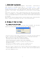
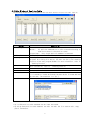
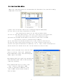
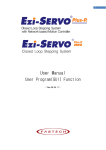
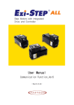
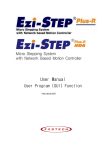
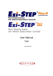
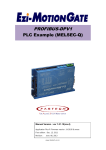
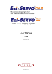
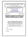
User Manual
Position Table
1
-
Table of Contents -
1. Before Getting Started____________________________________________________________________
3
2. Window of Position Table(PT)_____________________________________________________________
2.1 Opening_________________________________________________________________________
2.2 Main Window of Position Table___________________________________________________
2.3 Position Table Editor___________________________________________________________
3
3
4
5
3. Position Table(PT) Items_________________________________________________________________
3.1 Description of Position Table Items_____________________________________________
3.2 Command Items___________________________________________________________________
6
6
6
4. Executing Position Table(PT)_____________________________________________________________
4.1 Starting Position Table_________________________________________________________
4.2 General Operation Examples_______________________________________________________
4.3 Operation Modes_________________________________________________________________
4.3.1 Normal______________________________________________________________
4.3.2 Single Step_________________________________________________________
4.4 Teaching Function_______________________________________________________________
4.4.1 Teaching by User Program______________________________________________
4.4.2 Teaching by Input Signals_____________________________________________
4.5 Input Condition Jump Function___________________________________________________
4.5.1 Automatic Jump________________________________________________________
4.5.2 Jump by External Signals______________________________________________
4.6 Loop Condition Jump Function____________________________________________________
4.6.1 Setting the Loop______________________________________________________
4.6.2 Clearing Loop Counter_________________________________________________
4.7 Start/Stop Signal Function ______________________________________________________
9
9
9
10
10
10
11
11
12
13
13
14
15
15
16
17
2
1. Before Getting Started
The present Products 「 Ezi-SERVO Plus-R User Manual “ Position Table”」 explains position
table
functions
of
Ezi-SERVO
Plus-R.
Here
is
「
User
Manual_
Manual_Communication Function 」 with the present manual. Please
Text」,
「
User
utilize our product
afterward understanding about proper usage method with reading these contents carefully.
The word as ‘Position Table’ can be presented as PT ( Position Table ) from the following
text.
In particular, Please don’t forget to memorize whole matters that requires attention about
safety in 「 User Manual_ Text」 and should try to understand properly. Besides please be safe
to do not use the products improperly in any case. At worst, serious concern can be occurred
as like death.
We provide this instruction manual and other instruction manual as well. Please keep these
manuals in appropriate place whenever you need to find and read comfortably.
2. Windows of Position Table
2.1. Loading Position Table Data
When click the ‘Pos Table’ button on main menu of User Program(GUI), then the system
displays the following message box and loads data saved in RAM area of drive.
Functions of Position Table allows to process motions in the orders that were predefined
by user. In the case of this Ezi-SERVO Plus-R drive, up to 256 steps can be saved.
Major functions for saving items are shown as following:
(1) Editing function of Motion step (Input/Edit/Delete/Copy)
(2) Start and Stop function of Motion order at User Program(GUI)
(3) Start and Stop Motion function of by signal input from outside drive.
(4) Teaching function
(5) Functions to save Motion steps as file and to load them from file
(6) View function of current Position Table order under execution
When electric power is supplied to drive, the Position Table data saved in ROM area in drive
is copied to RAM area and once click the ‘Post Table’ button, then the system loads the
data saved in RAM area of drive.
3
2.2 Main Window of Position Table
The following window describes windows and buttons which execute the position table function.
Button
Normal/Single Step
Description
The user can select modes to execute the position table.
Normal : All position commands are in order executed according to
conditions saved in the position table.
Single Step : Only single position command is executed.
Run/Stop/Next
To run/stop items at the defined position table
Teaching
Teaching is executed by either using external input signal or user
program. By clicking this button, the user can easily use teaching
function at the user program window. For more information, refer to
‘Teaching Function’.
To display the position value measured by the teaching function. For
more information, refer to ‘Teaching Function’.
To save current position table data in ROM drive.
To open position table data saved in ROM drive
To save current position table data to an external file
(It is saved to a folder defined by the user with a file name defined
by the user. The extension is *.txt.)
To read position table data saved to external file
Refresh
Save to ROM
Load ROM
Save to file
Load File
* Up to 256 position table commands can be input and saved.
* By using each position table command, the user can edit the file such as edit, copy,
paste, and delete.
4
2.3. Position Table Editor
When click right mouse button on a selected Position Table data line, then the following
popup menu is activated.
(1) Edit Item: You can edit data on the following dialog box shown below.
(2) Clear Item: All the items of selected PT are cleared.
After executing this function all the items are shown as blank.
(3) Clear All Items: While above function “Clear Item” clears data for one selected order,
this function clears data for all the orders of 256 Position Table.
(4) Reload Item from ROM: The data shown on the screen are values saved in the RAM.
This function is used for reload data saved in ROM area.
(5) Cut Item: Used to cut selected item data of PT in order to paste on other position.
(6) Copy Item: Used to copy selected item data of PT in order to paste on other position.
(7) Paste Item: Right the copied data to clipboard by ”Cut”or “Copy”to other selected position.
(8) Run Selected Item: Execute motion order from the selected no of Position Table.
Double click on selected line of Position Table
data or click the “Edit Item” popup menu
button shown above figure, then the dialog box
shown right is activated.
Once complete editing of each item, and then you
move and select other items to edit by using
right/left arrow key.
After complete editing of all data, click
‘Save’ button to save data to RAM.
In order to save data to ROM area, click
‘Save to ROM’ button on main screen of
Position Table.
5
3. Position Table Item
3.1 Explanation of Position Table Item
Designated Item
Description
Unit
Lower limit Upper limit
Specifies type of motion.
Command
For
more
details,
refer
to
「3.2
-
0
9
pulse
-134,217,728
+134,217,727
pps
0
500,000
pps
0
500,000
ms
1
9,999
ms
1
9,999
ms
0
60,000
Command」.
Position
Specifies position/movement scale by
number of pulse.
Specifies low speed by number of pulse in
Low Speed
accordance with type of motion.
For
more
details,
refer
to
「3.2
Command」.
Specifies high speed by number of pulse
High Speed
in accordance with type of motion.
For
more
details,
refer
to
「3.2
Command」.
ACC time
DEC time
Wait time
Specified acceleration time by msec when
starting motion.
Specified acceleration time by msec when
stopping motion.
Specifies waiting time by msec for
starting motion of next PT when
specifying PT no for jump/skip.
If JP Table No is specified as blank or
‘Continuous Action’ is specified, this
is ignored.
Note) Even if Wait Time is specified as 0[ms], the system waits for the completion signal
of position setting (INP signal) or motor stop signal before starting next Position Table
Continuous action
If this item is checked
as ‘check
(1)’, the system continues actions of
current position and next position.
6
-
0
1
Example) When Position No 0, 1 are specified as under, that is, position 0 is specified as Continuous Action,
Speed
PT No
Cont Act
JPT No
Position 0
1
1
Position 1
0
Time
Position
0
:
Position
JP Table No.
JPT 0
JPT 1
JPT 2
Loop Count
Loop Jump Table No.
PT set
Loop Counter Clear
Check Inpos
When this item specified, the system
jumps to JP Table No and execute it after
completing action of current position.
If Position No is specified as 10XXX,
system jumps to Position No XXX as soon
as‘JPT Start’, one of the input digital
signal to controller from outside,
becomes ON.
For program exit, specify as blank.
For more details, refer to 「4.4 Input
Condition - Jump」.
If any of these items is checked and
there are corresponding input signals of
JPT input0, JPT input1 or JPT input2,
system jumps to JPT 0, JPT 1 or JPT 2
accordingly regardless of
specified ’Jump Table No.’.
For more details, refer to 「4.4 Input
Condition Jump」.
-
0
10,000
1
:
255
10,255
0
255
10000
10255
0
255
10000
10255
0
255
10000
10255
0
100
0
255
10,000
10,255
0
15
-
0
255
-
0
1
-
Input signal
Corresponding Input Jump Position
JPT input0
JPT input1
JPT input2
Input Jump Position No 0
Input Jump Position No 1
Input Jump Position No 2
If these item are specified, system
repeats action of the position specified
times (Loop Count) and after then jumps
to corresponding position to Loop Jump
Table No regardless of specified ’Jump
Table No’. For more details, refer to
「4.5.1 Loop Setting」.
Specifies output signals such as PT
Output0, PT Output1, PT Output2 in order
to confirm the start or stop of motor
operation for each position.
0,8: Not use output signal
1~7:Specifies output function when
starting operation
9~15: Specifies output function when
completing operation
For more details, refer to 「4.6
Start/Completion Alarm Function」.
If this item is checked, Loop Count of
specified no of PT is to be cleared.
For more details, refer to 「4.5.1 Loop
Setting」.
If this item is checked, stop condition
is recognized by Inposition finish.
7
-
3.2 Type of Command
Item “Command” is for specifying type of action pattern to be executed for each position and the
followings in the table are list of commands.
Command Name
Specified
Remark
Value
Abs Move low speed.
0
The value in the item “Position” is value
Abs Move high speed
1
for absolute position.
Abs Move high speed with deceleration.
2
Abs Move with acceleration and deceleration.
3
Inc Move low speed.
4
The value in the item “Position” is value
Inc Move high speed
5
for relative position.
Inc Move high speed with deceleration.
6
Inc Move with acceleration and deceleration.
7
Move to Origin
8
Clear Position
9
Execute the command to move to origin based
on the current parameters specified.
Reset ‘command position’ value and ‘actual
position’ vale based on current position and
clears the values as 0.
The following table shows speed patterns for each action of command.
Command Name
Specified
Value
Speed Pattern
Abs Move low speed.
0
Low speed
Inc Move low speed.
4
Abs Move high speed
1
High speed
Inc Move high speed
5
Abs Move high speed with deceleration.
2
High speed
Low speed
Inc Move high speed with deceleration.
6
Abs Move with acceleration and deceleration.
3
High speed
Low speed
Inc Move with acceleration and deceleration.
7
8
4. Execution of Position Table
When installing User Program(GUI), the following files are saved in the folder named as
“₩₩FASTECH₩₩EziMOTION PlusR₩₩PT_Samples” as sample files to test Position Table.
1) ₩₩PT_Samples₩₩Ezi-SERVO₩₩PTsample (General Motioning).txt
2) ₩₩PT_Samples₩₩Ezi-SERVO ₩₩PTsample (Loop Motioning).txt
3) ₩₩PT_Samples₩₩Ezi-SERVO ₩₩PTsample (Loop counter clear).txt
4) ₩₩PT_Samples₩₩Ezi-SERVO ₩₩PTsample (Clear Position).txt
4.1 How to start Position Table
Position Table operation is executed by input signal or communication command. The followings
are example of Position Table operation by input signal to be explained step by step.
In the case of Position Table operation by communication command, the system is executed by sending
the communication commands corresponding to the control input signal.
1. Specify Position Table No (0~255) operated by PT A0~PT A7.
2. If the motor is Servo OFF, turn ON Servo.
3. Signal ON of PTStart input to start operation.
4.2 Example for general operation
Specify PT No through input data for PT A0 ~ PTA7 and then input ‘PT Start’ signal to start speed
control operation.
【Specifying Position Table 】
Command
PT
Low
type
Position
No
Speed
High
Speed
Accel
time
Decel.
time
Wait
time
Continuous
Action
JP
Table
No.
0
3
10000
0
2500
50
300
0
1
1
1
0
1000
500
0
-
-
0
1
2
2
3
5000
0
1500
50
300
300
0
3
3
3
-2500
0
1000
300
300
0
0
-
* Refer to the sample file for test Position Table, ‘PTsample (General Motioning).fpt’.
9
4.3 Operation Modes
Position Table commands can be executed by two modes as follows.
4.3.1 Normal
Select ‘Normal’ at the main window of position table, and all commands will be
in order executed by conditions entered to PT data.
①
②
③
④
1) While Normal mode is selected, the user sets PT number to 0 and click ‘Run’ and
then PT 0 is executed.
2) PT 1 is executed by PT data jump conditions.
3) PT 2 is executed by PT data jump conditions.
4) As mentioned above, next PT number is automatically executed by position data jump
conditions.
5) Click ‘Stop’ to stop operating.
4.3.2 Single Step
Select ‘Single Step’ at the main window of position table, and only corresponding
PT command will be executed and next PT commands will be on standby. This mode can be
easily used when the user executes the test for each position command. And it is
available for User Program(GUI) only.
①
②
③
1) While Single Step Mode is selected, the user sets PT number to 0 and click ‘Run’
and then PT 0 is executed.
2) After execution is stopped, ‘Run’ icon is changed into ‘Next’ and next command
is on standby.
3) Click ‘Next’ button, and PT 1 will be executed.
4) When pressing each ‘Next’ button, one PT command is executed.
5) Click ‘Stop’ to stopping operating. After operation is stopped, the user can set
new PT number and click ‘Run’ button to start the program again.
10
4.4 Teaching Function
Teaching signal functions that the position value[pulse] being working can be automatically
inputted into a ‘position’ value of a specific position table.
The following table shows type of commands and whether teaching function can be used or not.
Command Name
Value
To be used or not
Abs Move low speed.
0
‘Teaching’ can be used.
Abs Move high speed
1
Abs Move high speed with deceleration.
2
Abs Move with acceleration and deceleration.
3
Inc Move low speed.
4
‘Teaching’
Inc Move high speed
5
used.
Inc Move high speed with deceleration.
6
Inc Move with acceleration and deceleration.
7
Move to Origin
8
Clear Position
9
cannot
be
4.4.1 Teaching by user program
When click ‘Teaching’ button on Position Table screen, the following dialog box is activated.
⑥
①
②
④
⑤
③
① Select Position Table No, the figure shows that no 6 of PT is selected among 256 Position Tables.
② Specify position of motor where to teach and move it.
③ Turn ON or OFF of Sevo during teaching.
④ Displays current position information and the value displayed in “Actual Pos(ition)”is to
be teaching value.
⑤ When
clicking this “Teaching” button, current value displayed in “Actual Pos” will be saved
in the item “Position” of the current PT (No 6 above case). The values are to be saved on RAM
and click ‘Save to ROM’ button in order to save on ROM.
⑥ In order to move next position, select PT no by using arrow keys.
11
4.4.2 Teaching by Input signal
You can save current position information to the Position Table data by turning ON teaching control
input signal. Also when executing teaching, position value (no. of pulse) is specified as absolute
position value. Teaching is carried out by following orders:
1. Select PT no. to save data and specify items like “Command”, etc.
(except item ’Position’)
2. Move motor to the position where you want to save data of it.
3. Specify PT no’s that teaching is carried out by ‘PT A0~PT A7’.
4. Turn ON teaching signal to save current position value into item ‘Position’of Position Table
data.
5. If you want to apply the saved value, you need to ‘Refresh’ PT data in order to verify the
value on the User Program(GUI) screen.
6. The values are to be saved on RAM and click ‘Save to ROM’ button in order to save on ROM.
PT No
(CMD)
Position Value for each PT
[pulse]
Position 3
12010
Position 4
15300
Position 12
-12800
Position 255
38520
12
4.5 Input Condition Jump
Among the items to be specified, “JP Table No.”, “JPT 0”, “JPT 1”and “JPT 2” are used
for specifying next PT no. to be executed. In specifying next PT no. to be executed, there are
two different methods depending on the control signal as followings:
4.5.1 Automatic Jump
This is the method to specify next action pattern (PT no.) by input condition.
System jumps to next PT no. to be executed automatically according to procedure.
For example as shown in the following figure, when PT no. 14 is executing, 1) if there is no
input signal, next action pattern is to be executed by PT no. 15 as shown in figure 1). However,
if any of input signal is ON such as JPT Input0, JPT Input1 or JPT Input2 during the operation
of PT no. 14, then system jumps to JPT 0, JPT 1 or JPT2 accordingly and execute it that is specified
in the Position Table data as shown in the figure 2) ~ 4).
PT No
(CMD)
Position Table No to
jump
(JP Table No.)
Input Jump
Position No 0
(JPT 0)
Input Jump
Position No 1
(JPT 1)
Data for PT no. 14
Input Jump
Position No 2
(JPT 2)
14
15
115
116
225
* Refer to the sample file for test Position Table, ‘PTsample (Loop Motioning).fpt’.
13
4.5.2 Jump by External Signal
This is the method to specify next action pattern (PT no.) by input condition.
However, system does not jump to next PT no. to be executed automatically according to procedure,
but executed by external signal (“JPT Start”).
Difference from the function in ‘section 4.5.1’executed by input signal JPT Input0~Input2
1) Jump Position No to jump need to have the format of 10XXX and
2) ‘JPT Start’ needs to be [ON] in order to execute the next action.
If specified “Wait Time” of PT data is more than 0, then the next action is to be executed
after the specified time from the external signal.
PT No
(CMD)
Wait Time
(Wait Time)
Position Table No
to jump
(JP Table No.)
14
0
10015
14
Input Jump
Position No 0
(JPT 0)
10115
Data for PT no 14
Input Jump
Input Jump
Position No 1 Position No 2
(JPT 1)
(JPT 2)
10116
10225
4.6 Loop Condition Jump
4.6.1 Specifying Loop
If 「Loop Count」and 「Loop Jump Table No」are specified, system repeats the action of position
specified times (Loop Count) and after then jumps to corresponding position to 「Loop Jump Table No. 」
regardless of specified「Jump Position No」, that is, 「Jump Position No」 is ignored.
There are rules in specifying loop as following:
1) If ‘0’is specified for 「Loop Count」, loop function is cancelled.
2) If system needs to jump before repeating the specified times, it jumps to JP Table No.
3) If ‘blank’is specified for 「Loop Jump Table No」, system exits execution.
4) If 「Loop Jump Table No」is specified in the form of 10XXX, next action is executed by the external
signal “JPT Start”.
Following Table is one of example for specifying loop.
Loop
Counter
Clear
(Loop Counter
Clear)
PT No
(CMD)
Movement
Scale
(Position)
Position Table
No to jump
(JP Table No.)
No of Loop
(Loop
Count)
Position Table No to jump
after completing loop
(Loop Jump Table No)
0
8000
1
0
0
-
1
4000
0
2
2
-
2
0
0
3
-
1
* Refer to the sample file for test Position Table, ‘PTsample (Loop Motioning).fpt
15
4.6.2 Loop Count Clear
“Loop Counter” is internal counter in drive to compare no. of repeat with the no. specified in
the item “Loop Count” of PT data.
This function clears “Loop Counter” to 0 (zero) of the specified PT data after completion of
looping. If 「Loop Count Clear」is specified as blank, this function is cancelled.
Following table shows an example of specifying Loop Counter Clear.
PT No
(CMD)
Movement
Scale
(Position
)
Position Table
No to jump
(JP Table No.)
No of Loop
(Loop
Count)
Position Table No to
jump after completing
loop
(Loop Jump Table No)
Loop
Counter
Clear
(Loop Counter
Clear)
0
8000
1
0
0
―
1
4000
0
2
2
―
2
0
0
0
0
1
1) Specify “Loop Counter Clear” of PT No 2 as PT No ‘1’.
2) Start operation from PT No 0.
When starting operation, system reset all “Loop Count” values as 0 (zero).
3) After repeats the loop block PT No 0 ~ PT No 1 two times, the “Loop Counter” becomes 2 (two)
same as specified “Loop Count” and so system completes looping and jumps to PT No 2.
4) After executing PT No 2, system jumps to PT No 0.
Before jumping to PT No 0, system clears “Loop Counter”- the internal counter as 0 (zero).
5) Then paragraph 3) and 4) are repeated infinitely.
6) If the “Loop Counter Clear” of PT No 2 was not specified, “Loop Counter” increased
continuously and so jumping to PT No 2 occurs only once at the first time and then repeats the
loop block PT No 0 ~ PT No 1 infinitely because the internal counter “Loop Counter” value will
never meet the specified “Loop Count” value.
* Refer to the sample file for test Position Table, ‘PTsample (Loop counter clear).fpt.
16
4.7 Start/Completion Signal Function
By specifying the item「Start/Completion Signal Function」, user can recognize the status of
Position Table whether it started operation, is under operation, or completed operation through
control signal output.
If you do not want to use 「Start/Completion Signal Function」, specify this item as 0 or 8.
If other value is specified, the position performs following actions depending on specified value.
・ If the value between 1 to 7 is specified for PT Set, PT Output HEX value is output through
output of ‘PT Output 0 ~ PT Output 2’at the time of starting operation.
・ If the value between 9 to 15 is specified for PT Set, PT Output HEX value is output through
output of ‘PT Output 0 ~ PT Output 2’after completion of operation.
PT Set
PT Output 2
PT Output 1
PT Output 0
PT Output
Value
Signal
Signal
Signal
HEX Value
0
OFF
OFF
OFF
0
1
OFF
OFF
ON
1
PT Output 0~2 signals turn
2
OFF
ON
OFF
2
to [ON] at the time of
3
OFF
ON
ON
3
starting operation of the
4
ON
OFF
OFF
4
corresponding PT.
5
ON
OFF
ON
5
6
ON
ON
OFF
6
7
ON
ON
ON
7
8
OFF
OFF
OFF
0
PT Output 0~2.
9
OFF
OFF
ON
1
PT Output 0~2 signals turn
10
OFF
ON
OFF
2
to [ON] after completion of
11
OFF
ON
ON
3
operation
12
ON
OFF
OFF
4
corresponding PT.
13
ON
OFF
ON
5
14
ON
ON
OFF
6
15
ON
ON
ON
7
Function
Not use output function of
PT Output 0~2.
Not use output function of
17
of
the
ⓒ Copyright 2008 FASTECH Co.,Ltd.
All Rights Reserved. Aug 05, 2009 rev.05.01.03
18