1
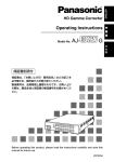
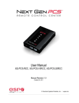
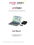
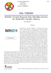
Software User Manual Software Version 1.0 © 2014 Electronic Systems Protection, Inc. / Technical Support: 1-800-645-9721 / espei.com Software User Manual I. INSTALLATION ......................................................................................................... 2 1. 2. 3. 4. COMPUTER REQUIREMENTS .................................................................................. 2 HARDWARE REQUIREMENTS .................................................................................. 2 Download and Install Software ............................................................................. 2 Install Data Interface Cable .................................................................................. 3 II. USING THE SOFTWARE ......................................................................................... 3 1. 2. 3. 4. PYSICAL CONNECTIONS .......................................................................................... 3 START THE SOFTWARE ............................................................................................ 3 CONFIGURE THE DATA CABLE AND COM PORT ......................................................... 4 SOFTWARE MODES ................................................................................................ 5 a. MULTIMETER MODE ............................................................................................ 6 b. SCOPE MODE ..................................................................................................... 7 c. CHART MODE ..................................................................................................... 9 d. OUTLET CONTROL MODE................................................................................... 10 e. HISTORICAL DATA MODE ................................................................................... 11 f. SETTINGS MODE ............................................................................................... 15 g. COM PORT SETUP MODE .................................................................................. 16 © 2014 Electronic Systems Protection, Inc. / Technical Support: 1-800-645-9721 / espei.com 1 Software User Manual I. Installation 1. Computer Requirements a. Minimum 133MHz Pentium processor (or equivalent), minimum 64MB of RAM, minimum 10MB free hard drive space, VGA or higher resolution monitor, keyboard, mouse, CD or DVD drive, minimum screen resolution of 1024x768, Microsoft Windows XP/Vista/7/8. 2. Hardware Requirements a. For use with enVision enabled products and Data Interface Cable (XG-PCS-1C-1) 3. Download and Install Software a. Download the Software Installer from www.espei.com. b. Unzip and run the installation utility. c. Follow the on-screen instructions to complete installation of the software. © 2014 Electronic Systems Protection, Inc. / Technical Support: 1-800-645-9721 / espei.com 2 Software User Manual 4. Install Data Interface Cable a. Automatic Installation (Requires Internet connection) i. Plug the USB side of the Data Interface Cable into an available USB port. ii. Windows will automatically detect and install appropriate device driver files for the Data Interface Cable. • • • If a “Found New Hardware” pop-up box appears, follow the onscreen instructions and allow Windows to search online for driver files. The installation could take several minutes to search for and download appropriate driver files. Once the files are found, follow the on-screen instructions to install. Note: The driver installation process will first install USB Serial Converter driver files, and then will install USB Serial Port drivers separately. b. Manual Installation In the event that the automatic driver installation process was not successful, or if no internet connection is available, the Data Interface Cable driver files may be installed manually. • • Select “Install Drivers” during the Software Installation process. Or run “enVision PCS Interface Setup” from: Start/All Programs/ESP SurgeX/ESP enVision PCS c. Once the Data Interface Cable has been successfully installed, it will appear in Device Manager as “USB Serial Port (COMx)” under “Ports (COM & LPT)”. II. Using the Software 1. Physical Connections a. Plug the USB side of the Data Interface Cable into an available USB port. b. Plug the RJ-11 side of the Data Interface Cable into the RJ-11 “OUT” jack labeled “Data Port” on the enVision enabled unit, which is the jack closest to the LCD. c. Note: The enVision PCS must be powered by AC Mains for communications with the software to operate. 2. Start the Software a. Double-click the desktop shortcut labeled “enVison”, or use the “ESP SurgeX enVision PCS” Start Menu shortcut located at: Start/All Programs/ESP SurgeX/enVision PCS © 2014 Electronic Systems Protection, Inc. / Technical Support: 1-800-645-9721 / espei.com 3 Software User Manual 3. Configure the Data Interface Cable and COM Port a. Click the COM Port Setup button labeled COM. b. Click Configure. i. The auto configuration process will automatically set the correct device parameters of the Data Interface Cable to operate properly with the software and enVision. • • Note: This process only needs to be done once for each new Data Interface Cable installed on the PC. Note: This process edits Windows registry values, and so may be blocked by MS Windows User Account Control (UAC) in Windows Vista/7/8. When using these operating systems, it may be necessary to exit the software and restart it with administrative rights by right-clicking the software shortcut and choosing “Run As Administrator”. © 2014 Electronic Systems Protection, Inc. / Technical Support: 1-800-645-9721 / espei.com 4 Software User Manual c. Click Detect. i. The auto detect process will automatically detect the COM Port number assigned to the Data Interface Cable. ii. If the auto detection process is successful, click Save. The software is now properly configured and ready for use. iii. If the auto detection process is not successful, verify that the Data Interface Cable device drivers are properly installed, and that the physical connections between the enVision and the PC have been made correctly. 4. Software Modes The enVision Software is organized into several operational modes. The modes are activated by clicking the corresponding button at the bottom of the software interface. Press the Help Button (“?”) in the upper right for additional information on the features available in the current mode. Hovering the mouse cursor over items will also display additional information. Scope Mode, Chart Mode, and Historical Data Mode include a Save function. Press the Save button to save data to a CSV file. Time Stamped data may also be saved as a report in PDF format. © 2014 Electronic Systems Protection, Inc. / Technical Support: 1-800-645-9721 / espei.com 5 Software User Manual a. Multimeter Mode i. The Multimeter Mode provides information traditionally acquired from one or more handheld digital multimeters, as well as an overview of the recorded power quality events and energy consumption of connected equipment. ±2% Measurement Accuracy. © 2014 Electronic Systems Protection, Inc. / Technical Support: 1-800-645-9721 / espei.com 6 Software User Manual ii. Real-time display of 8 electrical parameters • • • • • • • • Line Voltage: AC RMS Volts Line-Neutral (Line1-Line2) Load Current Draw: AC RMS Amps Load Power Draw: Watts Neutral-Ground Voltage: AC RMS Volts Neutral-Ground (Line2Ground) Line Frequency: Hertz Load Power Factor Line Voltage Crest Factor Energy Usage (kWh) of connected equipment since date and time of last manual usage reset iii. Number of recorded power quality events • • • • • • Surge Events: SG Overvoltage Events with turn off of connected equipment: OVoff Overvoltage Events with no turn off of connected equipment: OVrec Undervoltage Events with no turn off of connected equipment: UVrec Undervoltage Events with turn off of connected equipment: UVoff Power Outage Events: PO b. Scope Mode i. The Scope Mode enables a real-time voltage, current, and power oscilloscope which incorporates many functions available in standalone oscilloscopes. 4kHz Oscilloscope Bandwidth. ii. Ch1-Ch3 buttons toggle waveform displays. • • • Ch1 button toggles line voltage trace. Ch2 button toggles load current trace. Ch3 button toggles load power trace. © 2014 Electronic Systems Protection, Inc. / Technical Support: 1-800-645-9721 / espei.com 7 Software User Manual iii. Up ▲ and Down ▼ Arrow buttons adjust the vertical axis scaling of each channel. iv. Left ◄ and Right ► Arrow buttons adjust the horizontal (time) axis scaling. v. While in normal operation, pressing the Wait button will freeze the currently displayed waveform. vi. One Shot Trigger Function • • • • The scope may be set to acquire and hold a waveform display, triggered by either Voltage or Current level. Press the One Shot button above the desired channel. A trigger level cursor will appear on the display. Next, Drag the trigger level cursor to the desired amplitude and press the Wait button If the Voltage of Current exceeds the trigger level, the scope will hold the display © 2014 Electronic Systems Protection, Inc. / Technical Support: 1-800-645-9721 / espei.com 8 Software User Manual c. Chart Mode i. The Chart Mode enables a chart style data logging function of 8 electrical parameters. Data point measurements are acquired once per second. The measured parameters may be enabled or disabled by pressing the corresponding button. ii. Chart display of 8 electrical parameters: • • • • • • • • Line Voltage: AC RMS Volts Line-Neutral (Line1-Line2) Load Current Draw: AC RMS Amps Load Power Draw: Watts Neutral-Ground Voltage: AC RMS Volts Neutral-Ground (Line2Ground) Line Frequency: Hertz Load Power Factor Line Voltage Crest Factor Energy Usage (kWh) of connected equipment since date and time of last manual usage reset © 2014 Electronic Systems Protection, Inc. / Technical Support: 1-800-645-9721 / espei.com 9 Software User Manual d. Outlet Control Mode i. The Outlet Control Mode enables control of the AC outlets and provides information about wiring faults and abnormal line voltage. ii. Use the green On/Off button to manually turn the AC outlets on and off. • Pressing the blue Power Cycle button will result in the execution of a power cycle. When commanded, the outlets will turn off, and then back on, after a 90 second delay. The Power Cycle indicator will be illuminated while a power cycle is active. © 2014 Electronic Systems Protection, Inc. / Technical Support: 1-800-645-9721 / espei.com 10 Software User Manual e. Historical Data Mode The Historical Data Mode allows for the retrieval and display of the power quality event and electrical parameter data stored in the enVision internal memory. i. Time Stamped Power Quality Event Data • enVision is able to store and timestamp the 512 most recent power quality events in its internal memory. Press the Import Time Stamped Data button to download the event data. © 2014 Electronic Systems Protection, Inc. / Technical Support: 1-800-645-9721 / espei.com 11 Software User Manual • Twelve types of events are logged: Overload: Load current draw has exceeded 25A Surge: enVision has been exposed to a transient voltage in one of the 3 possible modes (between Live and Neutral, between Live and Ground, between Neutral and Ground) with a peak amplitude of 500V* or higher and a frequency of 20 kHz or higher. *500V surge voltage amplitude applies to IEEE C62.41 Category B Impulse; surge voltage amplitudes necessary for detection of other surge types may vary. Over Voltage (Cutoff): Line voltage exceeded the over voltage shutdown threshold, and connected equipment was turned off. Over Voltage (Record): Line voltage exceeded the over voltage record threshold, and connected equipment was not turned off. Under Voltage (Record): Line voltage dropped below the under voltage record threshold, and connected equipment was not turned off. Under Voltage (Cutoff): Line voltage dropped below the under voltage shutdown threshold, and connected equipment was turned off. Power Outage: Loss of AC power. Turn On: The enVision outlets were turned on. Turn Off (Cycle): A power cycle was initiated by a received command. Turn Off (Software): Outlets were turned off by a received command. Turn Off (Button): Outlets were turned off by the pushbuttons. Turn Off (Loss of Ground): Outlets were turned off due to the loss of the safety ground conductor at the wall receptacle. © 2014 Electronic Systems Protection, Inc. / Technical Support: 1-800-645-9721 / espei.com 12 Software User Manual ii. Historical Electrical Parameter Data Every 30 minutes, enVision stores a snapshot of 6 electrical parameters measured over the prior 30 minute interval. The internal memory can store 138 days of data. Press the Import Historical Data button to download the data. Six electrical parameters are logged: • Average Power (Watts): The average real power draw of connected equipment during the 30 minute recording interval. Maximum Power Draw (Watts): The highest real power draw measured during the 30 minute recording interval. Average Recorded Voltage (VRMS): The average line voltage during the 30 minute recording interval. Maximum Recorded Voltage (VRMS): The highest line voltage measured during the 30 minute recording interval. Minimum Recorded Voltage (VRMS): The lowest line voltage measured during the 30 minute recording interval. Maximum Recorded Current (ARMS): The highest current draw measured during the 30 minute recording interval. After the historical electrical parameter data has been downloaded, it may be saved to a file or graphically displayed by pressing one of the 3 Graph buttons. © 2014 Electronic Systems Protection, Inc. / Technical Support: 1-800-645-9721 / espei.com 13 Software User Manual 1. Average Power Graph Pressing the Average Power Graph button will display a bar graph of the average real power draw of connected equipment during each 30 minute recording interval. 2. Average Voltage Graph Pressing the Average Voltage Graph button will display a bar graph of the average line voltage during each 30 minute recording interval. © 2014 Electronic Systems Protection, Inc. / Technical Support: 1-800-645-9721 / espei.com 14 Software User Manual 3. Max/Min Graph Pressing the Max/Min Graph button will display line graphs of maximum voltage, minimum voltage, maximum current draw, and maximum power draw during each 30 minute recording interval. Pressing the V Max, V Min, I Max, or P Max buttons will enable or disable the display of the corresponding parameter. f. Settings Mode i. The Settings mode enables the specification of the user-configurable parameters of enVision. When this mode is entered, it displays the parameters currently in use. ii. Auto Set Clock: Automatically sets the internal clock to the current date and time. iii. Set Clock: Sets the internal clock to a date and time manually specified in the date/time field. © 2014 Electronic Systems Protection, Inc. / Technical Support: 1-800-645-9721 / espei.com 15 Software User Manual iv. Update ID: Sets the product identifier specified in the text box. 10 character limit. v. Update Limits: Sets the 6 voltage thresholds specified by the voltage threshold selection fields. Limit When Activated Action Over Voltage Shutdown Over Voltage Record Over Voltage Restore Under Voltage Restore Under Voltage Record Under Voltage Shutdown V > OVShutdown Outlets turned Off and event recorded Outlets stay On and event recorded Outlets turned On and event recorded Outlets turned On and event recorded Outlets stay On and event recorded Outlets turned Off and event recorded OVShutdown > V > OVRecord V < OVRestore After OVShutdown V > UVRestore After UVShutdown UVShutdown < V < UVRecord V < UVShutdown Factory Default 120V 208/240V 150 280 145 270 140 260 105 190 100 180 80 160 g. COM Port Setup Mode i. The COM Port Setup mode is used to configure new Data Interface Cables for use. ii. Detect: Automatically detect the COM Port when the enVision, Data Interface Cable, and PC are properly connected and powered up. iii. Configure: Automatically configure the advanced settings of the Data Interface Cable. May require running the software with elevated permissions (right-click program shortcut and choose “Run As Administrator”) on Windows Vista/7/8 with UAC (User Account Control) enabled. iv. Save: Saves the COM Port selection. © 2014 Electronic Systems Protection, Inc. / Technical Support: 1-800-645-9721 / espei.com 16