1
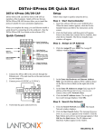
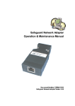
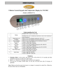
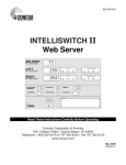
RP-IP
RP-IP-GNS
User Manual
© 2015 Electronic Systems Protection, Inc. / Technical Support: 1-800-645-9721 / espei.com / UM-Remote-Portal-Rev-B
User Manual
© 2015 Electronic Systems Protection, Inc. / Technical Support: 1-800-645-9721 / espei.com
Page 1
User Manual
I. HARDWARE
3
1. RP-IP ............................................................................................................................. 3
2. RP-IP-GNS .................................................................................................................... 3
II. SETUP AND CONFIGURATION
4
1. IP SETTINGS AND CONFIGURATION ....................................................................................4
2. LAN OPERATION AND CONFIGURATION ..............................................................................4
3. WAN CONFIGURATION .....................................................................................................8
III. OPERATION
1.
2.
3.
4.
9
JAVA APPLET .................................................................................................................. 9
MOBILE ..........................................................................................................................10
SNMP …………………….……………………………………………………………………..10
COM PORT REDIRECTION .......…………………….…………………………………………..10
IV. ADVANCED CONFIGURATION
11
V. FIRMWARE UPGRADE
13
VI. SPECIFICATIONS
14
© 2015 Electronic Systems Protection, Inc. / Technical Support: 1-800-645-9721 / espei.com
Page 2
User Manual
I.
HARDWARE:
1.
RP-IP
a. LAN: Connect to local network using Cat5e patch cable
b. XG / EV Data Port: Connect to XG or EV product using 6p6c
RJ25 patch cable with Standard pin out
c. Power: Input power connection. USB Mini B, 5VDC, 500mA
minimum
d. LEDs:
LED State
Meaning
EV, XG Toggle
EV solid, XG off
XG solid, EV off
e. Buttons:
Button
Reset
Mode
2.
Establishing network connectivity
enVision operating mode
Next Gen operating mode
Action
Press and hold for 5 seconds, then release to reset the unit to factory defaults. Will reset IP
settings to factory default.
Press and hold for 5 seconds, then release to toggle between EV and XG operating modes
RP-IP-GNS
a. LAN: Connect to local network using Cat5e patch cable
b. XG / EV Data Port: Connect to XG or EV product using
6p6c RJ25 patch cable with Standard pin out
c. Power: Input power connection. Barrel, 12VDC, 1A
minimum
d. LEDs:
LED State
EV, XG Toggle
EV solid, XG off
XG solid, EV off
Switch Status
Power
e. Buttons:
Button
Reset
Mode
Meaning
Establishing network connectivity
enVision operating mode
Next Gen operating mode
Link/Activity LEDs for each switch
port
RP-IP-GNS Power Indicator
Action
Press and hold for 5 seconds, then release to reset the unit to factory defaults. Will reset IP
settings to factory default.
Press and hold for 5 seconds, then release to toggle between EV and XG operating modes
© 2015 Electronic Systems Protection, Inc. / Technical Support: 1-800-645-9721 / espei.com
Page 3
User Manual
II.
SETUP AND CONFIGURATION:
1.
IP Settings and Configuration
a. Factory Default: Acquires IP address automatically via DHCP
b. Determine assigned IP address by one of the following methods:
2.
i
Access router table
ii
Download and run ESP RP-IP Discover Utility available on the Downloads tab here:
http://www.espei.com/products/remote-portal
iii
Download and install Lantronix DeviceInstaller:
http://www.lantronix.com/device-networking/utilities-tools/device-installer.html
LAN Operation and Configuration
a. Using a web browser with JavaScript enabled, navigate to http://IPAddress/config where the
IPAddress is the IP Address of the RP-IP.
i
When prompted for a User Name and Password, leave both fields blank and press
Log In.
ii
Important: For any changes to be applied, press the OK button at the bottom of the
section, then press Apply Settings in the left hand menu, and finally wait for the
RP-IP to reboot with new settings in place.
iii
Home Page: View firmware and configuration information currently in use.
© 2015 Electronic Systems Protection, Inc. / Technical Support: 1-800-645-9721 / espei.com
Page 4
User Manual
b. Network Settings: View and change IP Configuration.
i. Select Obtain IP address automatically to automatically receive an IP address
1) BOOTP: Select Enable to permit the Bootstrap Protocol (BOOTP) server to
assign the IP address from a pool of addresses automatically. Enable is the
default.
2) DHCP: Select Enable to permit the Dynamic Host Configuration Protocol (DHCP)
to assign a leased IP address to the RP-IP automatically. Enable is the default.
3) AutoIP: Select Enable to permit the RP-IP to generate an IP in the 169.254.x.x
address range with a Class B subnet. Enable is the default.
4) DHCP Host Name: Enter the desired host name for the RP-IP.
© 2015 Electronic Systems Protection, Inc. / Technical Support: 1-800-645-9721 / espei.com
Page 5
User Manual
ii. Select Use the following IP configuration to manually specify the IP address.
1) IP Address: If DHCP is not used to assign IP addresses, enter it manually in
decimal-dot notation. The IP address must be set to a unique value in the
network.
2) Subnet Mask: A subnet mask defines the number of bits taken from the IP
address that are assigned for the host part.
3) Default Gateway: The gateway address, or router, allows communication to other
LAN segments. The gateway address should be the IP address of the router
connected to the same LAN segment as the unit. The gateway address must be
within the local network.
4) DNS Server: The DNS server allows the name of a remote machine to be
resolved automatically. Enter the IP address of the DNS server. If the device is
DHCP enabled, the DHCP server provides the DNS server IP address, which will
override this configured value. Note: This setting is applicable only in Manual
Connection mode.
iii. SNMP
1) Select Enable or Disable to enable or disable the SNMP protocol.
2) SNMP Manager: Specify the IP address of the SNMP manager.
3) The SNMP MIB may be downloaded on the Downloads tab on this page:
http://www.espei.com/products/remote-portal
iv. Ethernet Configuration
1) Auto Negotiate: With this option, the Ethernet port auto-negotiates the speed and
duplex with the hardware endpoint to which it is connected. This is the default.
2) Speed: The speed of data transmission. The default is 100 Mbps. This option is
only available when Auto Negotiate is not enabled.
3) Duplex: The direction of data transmission. The default is Full. This option is only
available when Auto Negotiate is not enabled.
© 2015 Electronic Systems Protection, Inc. / Technical Support: 1-800-645-9721 / espei.com
Page 6
User Manual
c.
Server: View and change the embedded Server settings.
i. PCS Communication
1) Mode: Select enVision (EV) or NextGen (XG) operational mode.
2) TCP Server Port: Specify the port for serial data.
ii. Server Configuration
1)
2)
Enhanced Password: Selecting this option enables advanced password creation,
allowing you to create passwords up to 16 bytes in length. Disabling this option
disables advanced password creation, allowing you to create basic passwords up
to 4 bytes in length.
Telnet/Web Manager Password: Enter the password required for Telnet
configuration and Web Manager access.
© 2015 Electronic Systems Protection, Inc. / Technical Support: 1-800-645-9721 / espei.com
Page 7
User Manual
iii. Advanced
1) ARP Cache Timeout: When the unit communicates with another device on the
network, it adds an entry into its ARP table. ARP Cache timeout defines the
number of seconds (1-600) before it refreshes this table.
2) TCP Keepalive: TCP Keepalive time defines how many seconds the unit waits
during an inactive connection before checking its status. If the unit does not
receive a response, it drops that connection. Enter a value between 0 and 60
seconds. 0 disables keepalive. The default setting is 45.
3) Monitor Mode @ Bootup: Select Disable to disable entry into the monitor mode
using the 'yyy' or 'xx1' key sequence at startup. This field prevents the unit from
entering monitor mode by interpreting the stream of characters that are received
during the device server's initialization at startup.
4) CPU Performance Mode: Do not adjust. Default is Regular.
5) HTTP Server Port: This option allows the configuration of the web server port
number. The valid range is 1-65535. The default port is 80.
6) Config Server Port: Not applicable.
7) MTU Size: The Maximum Transmission Unit (MTU) is the largest physical packet
size a network can transmit for TCP and UDP. Enter between 512 and 1400
bytes. The default is 1400 bytes.
8) TCP Re-transmission timeout: The desired TCP re-transmission timeout value. If
the ACK is not received for a packet sent from the RP-IP device, then the unit will
retransmit the data. The valid range is 500-4000 msec. The default is 500 msec.
3.
d.
Apply Settings: Applies the currently specified settings.
e.
Apply Defaults: Reset the unit to factory defaults. Will not modify IP settings.
WAN Configuration
a.
To access the RP-IP Java applet from outside of the local network, the following 2 ports
must be forwarded through the firewall to the internal IP address of the RP-IP:
i. HTTP Server Port (Default 80)
ii. TCP Server Port (Default 10001)
b. To access the RP-IP mobile page from outside of the local network, the following port must
be forwarded through the firewall to the internal IP address of the RP-IP:
i. HTTP Server Port (Default 80)
© 2015 Electronic Systems Protection, Inc. / Technical Support: 1-800-645-9721 / espei.com
Page 8
User Manual
III.
OPERATION:
1.
Java Applet
a. Download and install the current JRE from: www.java.com
Java applet operation requires a computer with an operating system which supports the
installation of a Java Runtime Environment (JRE), including MS Windows, Apple OSX, and
various Linux distributions.
b. Using a web browser, navigate to the IP address of the RP-IP. Include the HTTP Server Port
if set to a value other than 80 in this format: http://IP:PORT
enVision PCS Mode
enVision PCS Mode
Next Gen PCS Mode
Next Gen PCS Mode
c. Refer to the enVision Software User Manual for information regarding software operation:
http://espei.com/products/envision/
© 2015 Electronic Systems Protection, Inc. / Technical Support: 1-800-645-9721 / espei.com
Page 9
User Manual
2.
Mobile
a. When using a browser which does not support Java, a link to the mobile page will be
provided. The mobile page requires that JavaScript be enabled.
enVision PCS Mode
3.
Next Gen PCS Mode
SNMP
a. The RP-IP and RP-IP-GNS provide monitoring and control via SNMP. The SNMP MIB may
be downloaded here: http://www.espei.com/products/remote-portal
4.
COM Port Redirection
a. The RP-IP and RP-IP-GNS may also be used with COM Port Redirection software and the
standard Next Gen PCS and enVision PCS desktop software applications.
© 2015 Electronic Systems Protection, Inc. / Technical Support: 1-800-645-9721 / espei.com
Page 10
User Manual
IV.
ADVANCED CONFIGURATION:
1.
Advanced settings may be adjusted via Telnet on port 9999.
a. Upon establishing a connection, the following information is displayed:
*** ESP PCS ***
MAC address 0080A39C878F
Software version V6.9.0.3 (140902) CPK6903_XPT05
Press Enter for Setup Mode
b. To enter Setup Mode, press Enter within 5 seconds. The configuration settings display,
followed by the Change Setup menu:
enVision (EV) Mode
*** basic parameters
Hardware: Ethernet TPI
IP addr - 0.0.0.0/DHCP/BOOTP/AutoIP, no gateway
SNMP Manager not set
DHCP device name : not set
*** Security
SNMP is
enabled
SNMP Community Name: public
Telnet Setup is
enabled
TFTP Download is enabled
Port 77FEh is
enabled
Web Server is
enabled
Web Setup is
enabled
ECHO is
disabled
Enhanced Password is disabled
***************** Channel 1 *****************
Connect Mode : C0
Source Port
: 10001
Destination Port : 00000
Destination IP : 0.0.0.0
CPU performance : Standard
Change Setup:
0 Server configuration
1 Channel 1 configuration
5 Debug
6 Security
7 factory defaults
8 exit without save
9 save and exit
Your choice ?
c. Select an option on the menu by entering the number of the option in the Your choice ? field
and pressing Enter.
d. To enter a value for a parameter, type the value and press Enter, or to confirm a current
value, just press Enter.
e. Important: When you are finished, save the new configuration (option 9). The unit reboots.
© 2015 Electronic Systems Protection, Inc. / Technical Support: 1-800-645-9721 / espei.com
Page 11
User Manual
f. Server configuration: Allows for the configuration of the following parameters:
•
IP Address
•
Gateway IP Address
•
Netmask
•
SNMP Manager IP Address
•
Telnet configuration password
•
DHCP device name
•
DHCP FQDN option
g. Channel 1 configuration: Allows for the configuration of the following parameters:
•
Connect Mode (Do not modify. Default is C0.)
•
Source Port
•
Destination Port (Currently Unused)
•
Destination IP (Currently Unused)
•
Enable Pack Control (Do not modify. Default is No.)
•
Disconnect Time
h. Debug: Not intended for general use. Enables EV/XG data communication debug.
i. Security: Allows for the configuration of the following parameters:
•
Disable SNMP
•
SNMP Community Name
•
Disable Telnet Setup
•
Disable TFTP Firmware Update
•
Disable Port 77FEh (configuration port)
•
Disable Web Server
•
Disable Web Setup
•
Disable ECHO ports
•
Enable Enhanced Password
•
Use Encryption (Currently Unused)
j. Factory defaults: Reset the unit to factory defaults. Will not modify IP settings.
k. Exit without save: Exits and terminates telnet session without modifying parameters.
l.
Save and exit: Stores parameters and reboots with new parameters in place.
© 2015 Electronic Systems Protection, Inc. / Technical Support: 1-800-645-9721 / espei.com
Page 12
User Manual
V.
FIRMWARE UPGRADE:
1.
Download and install the Lantronix Device Installer: http://www.lantronix.com/devicenetworking/utilities-tools/device-installer.html
2.
Download the Remote Portal firmware file (*.lxi format): http://espei.com/products/remote-portal/
3.
Start the Lantronix Device Installer. The RP should be automatically detected, and listed on the
right side with a name of “XPort-05”
4.
Select the unit by clicking on its name, and then press the “Upgrade” button now available on the
top menu bar
5.
A Device Upgrade Wizard window will
open
Select “Use a specific installation file…”
and then click the “Browse” button
6.
Navigate to the firmware file (*.lxi), select
it, and press the “Open” button
© 2015 Electronic Systems Protection, Inc. / Technical Support: 1-800-645-9721 / espei.com
Page 13
User Manual
VI.
7.
Click the “Next” button on the wizard to
begin the upgrade process
8.
Close the Device Upgrade Wizard when the
upload process is complete, and then close
the Device Installer Utility
SPECIFICATIONS:
Parameter
Power Requirement
Specification
RP-IP
RP-IP-GNS
Network Interface
Protocols Supported
LEDs
Dimensions
Weight
Temperature Range
Humidity Range
Agency Listings
RP-IP
RP-IP-GNS
RP-IP
RP-IP-GNS
RP-IP
RP-IP-GNS
5VDC, 2W
12VDC, 2W
RJ45 Ethernet 10BASE-T or 100BASE-TX (auto-sensing)
ARP, TCP/IP, Telnet, SNMP, DHCP, BOOTP, TFTP, Auto IP,
and HTTP
10BASE-T & 100BASE-TX Link Activity, Full/half duplex.
EV/XG mode indicators.
3.38” W x 2.2” D x 0.9” H
6.5” W x 2.75” D x 1” H
0.2 lbs.
0.5 lbs.
5C to 40C
5% to 95% R.H. Non-condensing
ETL Certified to UL 60950-1 (In Progress)
© 2015 Electronic Systems Protection, Inc. / Technical Support: 1-800-645-9721 / espei.com
Page 14