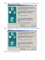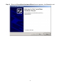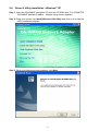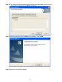
1
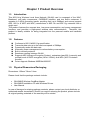
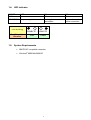
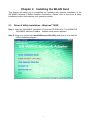
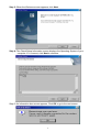
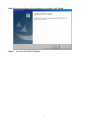
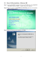
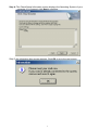
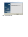
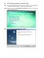
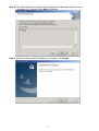
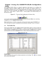
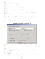
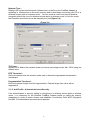
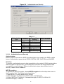
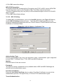
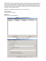
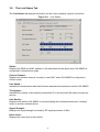
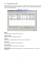
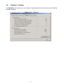
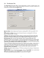
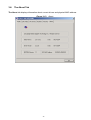
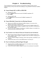
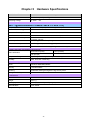
GN-WMKG
IEEE 802.11b/g CardBus Wireless LAN Card
User’s Manual
http://www.gigabyte.com.tw
Rev. 2.0 First Edition
Federal Communication Commission Interference Statement
This equipment has been tested and found to comply with the limits for a Class B digital
device, pursuant to Part 15 of the FCC Rules. These limits are designed to provide
reasonable protection against harmful interference in a residential installation. This
equipment generates, uses and can radiate radio frequency energy and, if not installed
and used in accordance with the instructions, may cause harmful interference to radio
communications. However, there is no guarantee that interference will not occur in a
particular installation. If this equipment does cause harmful interference to radio or
television reception, which can be determined by turning the equipment off and on, the
user is encouraged to try to correct the interference by one of the following measures:
- Reorient or relocate the receiving antenna.
- Increase the separation between the equipment and receiver.
- Connect the equipment into an outlet on a circuit different from that to which the receiver
is connected.
- Consult the dealer or an experienced radio/TV technician for help.
FCC Caution: To assure continued compliance,any changes or modifications not
expressly approved by the party responsible for compliance could void the user's authority
to operate this equipment.
This device complies with Part 15 of the FCC Rules. Operation is subject to the following
two conditions: (1) This device may not cause harmful interference, and (2) this device
must accept any interference received, including interference that may cause undesired
operation.
IMPORTANT NOTE:
FCC Radiation Exposure Statement:
This equipment complies with FCC radiation exposure limits set forth for an uncontrolled
environment. End users must follow the specific operating instructions for satisfying RF
exposure compliance.
This transmitter must not be co-located or operating in conjunction with any other antenna
or transmitter.
Contents
CHAPTER 1 PRODUCT OVERVIEW
1-1.
1-2.
1-3.
1-4.
1-5.
INTRODUCTION ...........................................................................................................1
FEATURES .................................................................................................................1
PHYSICAL DIMENSIONS/PACKAGING .............................................................................1
LED INDICATOR .........................................................................................................2
SYSTEM REQUIREMENTS ............................................................................................2
CHAPTER 2
2-1.
2-2.
2-3.
2-4.
INSTALLING THE WLAN CARD
®
15
THE PROFILE TAB ....................................................................................................15
THE LINK STATUS TAB .............................................................................................22
THE SITE SURVEY TAB.............................................................................................23
“STATISTICS” SETTING .............................................................................................24
THE ADVANCE TAB ..................................................................................................25
THE ABOUT TAB ......................................................................................................26
CHAPTER 4
3
DRIVER & UTILITY INSTALLATION - WINDOWS 98SE ....................................................3
DRIVER & UTILITY INSTALLATION - WINDOWS® ME .......................................................6
DRIVER & UTILITY INSTALLATION - WINDOWS® 2000.....................................................9
DRIVER & UTILITY INSTALLATION - WINDOWS® XP ......................................................13
CHAPTER 3 USING THE GIGABYTE WLAN
CONFIGURATION UTILITY
3-1.
3-2.
3-3.
3-4.
3-5.
3-6.
1
TROUBLESHOOTING
27
CANNOT ENABLE 802.1X, WPA OR WPA-PSK..........................................................27
CANNOT ESTABLISH CONNECTION TO A WIRELESS NETWORK ......................................27
CAN CONNECT TO AN ACCESS POINT, BUT CANNOT ACCESS THE INTERNET .................27
POOR LINK QUALITY AND WEAK SIGNAL STRENGTH ....................................................27
CHAPTER 5
HARDWARE SPECIFICATIONS
28
Chapter 1 Product Overview
1-1. Introduction
This 802.11b/g Wireless Local Area Network (WLAN) card is composed of the MAC,
Baseband, and radio components, CARDBUS interface, and two built-in antennas. It
operates in 2.4GHz frequency bands, providing fast (up to 54Mbps) and secure (support
AES, 802.1x & WEP and WAP) connections to 802.11b and 802.11g networks from a
single card.
This product features the compact size, low power consumption, and power management
functions, and provides a high-speed wireless data communication. Therefore, this
product is ideally suitable for being integrated into the personal mobile and handheld
platform.
1-2. Features
Conforms to 802.11b/802.11g specification.
Transmits data rate up to the maximum speed of 54Mbps.
Dynamically scales the data rate.
Automatic power management to reduce battery consumption.
Built-in diversity antenna.
Seamless roaming between WLAN.
Supports AES (Advance Encryption System), enterprise-class 802.1x security and
multiple levels of WEP encryption (64-bit /128-bit), and WPA (Wi-Fi Protected
Access)..
Driver supports Windows 98SE/Me/2000/XP.
1-3. Physical Dimensions/Packaging
Dimensions: 120mm* 54mm* 6mm
Please check that the package contents include:
•
•
•
GN-WMKG Wireless CardBus Adapter
GN-WMKG Installation CD with Windows Drivers
User Manual
In case of damaged or missing package contents, please contact your local distributor or
authorized reseller immediately. Should you require returning the product, please include
all original packing materials or the warranty will be voided.
1
1-4. LED Indicator
POWER
LINK
OFF
CONDITION No power applied to card
LED Blinking
Condition of the
Receiver
GIGABYTE
Link
ON
ON
ON
Blink
Looking for network
association
Adapter has an
active connection
GIGABYTE
Power
1-5. System Requirements
•
IBM PC/AT compatible computer
•
Windows® 98SE/Me/2000/XP
2
Chapter 2
Installing the WLAN Card
This chapter will assist you in completing the hardware and software installation of the
GN-WMKG Wireless CardBus Adapter successfully. Please refer to the driver & utility
installation section that matches your operating system.
2-1. Driver & Utility Installation - Windows® 98SE
Step 1: Insert the GN-WMKG Installation CD into the CD-ROM drive. The GIGABTYE
GN-WMKG Wireless CardBus Adapter setup screen appears.
Step 2: Drag your mouse over Install Wireless LAN Utility and click on it to start the
utility installation program.
3
Step 3: When the Welcome screen appears, click Next.
Step 4: The Check Setup Information screen displays the Operating System of your
computer. If it is correct, click Next to continue.
Step 5: An information box screen appears. Click OK to go to the next screen.
4
Step 6: After the software utility installation is complete, click Finish.
Step 7: Insert the GN-WMKG Adapter.
5
2-2. Driver & Utility Installation - Windows® ME
Step 1: Insert the GN-WMKG Installation CD into the CD-ROM drive. The GIGABTYE
GN-WMKG Wireless CardBus Adapter setup screen appears.
Step 2: Drag your mouse over Install Wireless LAN Utility and click on it to start the
utility installation program.
Step 3: When the Welcome screen appears, click Next..
6
Step 4: The Check Setup Information screen displays the Operating System of your
computer. If it is correct, click Next to continue.
Step 5: An information box screen appears. Click OK to go to the next screen.
7
Step 6: After the software utility installation is complete, click Finish.
Step 7: Insert the GN-WMKG Adapter.
8
2-3.
Driver & Utility Installation - Windows® 2000
Step 1: Insert the GN-WMKG Installation CD into the CD-ROM drive. The GIGABTYE
GN-WMKG Wireless CardBus Adapter setup screen appears.
Step 2: Drag your mouse over Install Wireless LAN Utility and click on it to start the
utility installation program.
Step 3: When the Welcome screen appears, click Next.
9
Step 4: The Check Setup Information screen displays the Operating System of your
computer. If it is correct, click Next to continue..
Step 5: After the software utility installation is complete, click Finish.
10
Step 6: The screen below will appear. This does not mean there is a problem. Click
Yes to continue with installation.
Step 7: If the screen below appears, this does not mean there is a problem. Click Yes to
continue.
Step 8: Insert the GN-WMKG Adapter.
11
Step 9: When the Found New Hardware Wizard screen appears, click Cancel to exit.
12
2-4. Driver & Utility Installation - Windows® XP
Step 1: Insert the GN-WMKG Installation CD into the CD-ROM drive. The GIGABTYE
GN-WMKG Wireless CardBus Adapter setup screen appears.
Step 2: Drag your mouse over Install Wireless LAN Utility and click on it to start the
utility installation program.
Step 3: When the Welcome screen appears, click Next..
13
Step 4: The Check Setup Information screen displays the Operating System of your
computer. If it is correct, click Next to continue.
Step 5: After the software utility installation is complete, click Finish.
Step 6: Insert the GN-WMKG Adapter.
14
Chapter 3 Using the GIGABYTE WLAN Configuration
Utility
The Gigabyte WLAN Utility is a powerful application that helps you to configure the
GN-WMKG Wireless CardBus Adapter as well as monitor the network status link. It
automatically appears as an icon in the system tray at the bottom right corner of screen
whenever the card is operating (see Figure 3-1). The icon displays signal strength (one
green box = weak signal, 4 green boxes = strong signal) and double-clicking on it
launches the utility.
Figure 3-1.
The icon of the Configuration & Monitor Utility
You may also open the Gigabyte WLAN Utility from the Windows Start menu, selecting
Programs and then Gigabyte WLAN Utility.
Note: Modifications to WLAN configuration settings can be done when GN-WMKG is in
use or through the network configuration tool provided by Windows® when it is inactive.
3-1.
The Profile Tab
Click on the Profile tab in the Gigabyte WLAN Configuration Utility to view the values for
each defined profile. Click the Add button to create a new profile (see section below for
further details), the Delete button to delete a selected profile, the Edit button to modify a
selected profile and click the Activate button to have a selected profile become active.
Figure 3-2 Profile Tab
Profile Name Name associated with specific wireless parameters and settings. The
the currently active profile.
15
icon indicates
SSID –
Displays the Service Set Identity (wireless network name) associated with active profile.
Channel –
Displays which channel the profile is operating on.
Authentication –
Displays authentication type associated with profile.
Encryption –
Four encryption types currently used in the profile include “None”, “WEP”, “AES” and
“TKIP”.
Network Type –
Displays the wireless mode (Infrastructure or Ad-Hoc) associated with the profile.
3-1-1. Add Profile – Configuration Tab
Figure 3-3
Add Profile – Configuration Tab
Profile Name –
Type in a unique profile name, set the corresponding parameters and click the Apply
button to add profile.
SSID –
Select a defined Service Set Identity detected by the system from the drop-down list or
input a new SSID (32-character maximum).
Power Saving Mode –
Select the PSM option to enable power saving feature (when no data will be transmitted)
or the CAM option to have device always on.
16
Network Type –
Displays the current wireless mode (Infrastructure or Ad-Hoc) the CardBus Adapter is
operating in. Infrastructure is the most common and is used when connecting your PC to a
wireless access point or wireless router. Ad-Hoc mode is used to connect to another
computer without the use of a wireless access point or wireless router. In Ad-Hoc mode,
the Preamble and Channel can be manually set (see Figure 3-4).
Figure 3-4
TX Power –
Allows you to define the transmit power at various percentage levels with 100% being the
default value.
RTS Threshold –
Define the packet size the wireless node uses to determine appropriate transmission
mechanism.
Fragmentation Threshold –
Define the packet length used for fragmentation. Packets larger than value will be
fragmented.
3-1-2. Add Profile - Authentication and Security
If an authentication or security setting is configured in a wireless access point or wireless
router, it is necessary for the Wireless CardBus Adapter profile to match the security
parameters in order to obtain access and establish a connection. Both WEP Encryption
and 802.1X Authentication protocols are supported.
17
Figure 3-5.
Authentication and Security
Authentication
Security
Type
None
None
WEP
Shared
None
WEP
WPA
TKIP
AES
WPA-PSK
TKIP
AES
Table 3-1
Secure Key
Setting
None
Key Setting
None
Key
None
None
WPA-PSK Key
WPA-PSK Key
802.1X Enabled
YES
YES
YES
NO
3-1-2-1. Authentication and Security
Authentication –
Before a station connects to a SSID, the authentication type used by the SSID must be
known. Authentication types include OPEN SYSTEM, WAP, WAP-PSK and SHARED.
Security –
To prevent unauthorized access to data transmitted on the network, WLAN card provide a
data encryption of high security. The access point must have the same password and
encryption to connect with you. Different authentication types have different level of
security. Please refer to Table 3-1.
WEP Encryption –
To activate the WEP Encryption, choose WEP Encryption from the drop-down menu in
the Encryption field. Then follow instructions below:
1. Select a Key. (You may specify up to 4 Keys)
2. Select data type as either Hex or ASCII. (Hex = hexadecimal)
3. Enter a WEP key. [For 64-bit: 10 hexadecimal digits, 5 ASCII; For128-bit: 26
hexadecimal digits, 13 ASCII]
18
4. Click OK to save the settings.
WPA-PSK Encryption –
To activate WPA-PSK (Preshared Key) Encryption using TKIP or AES, choose WPA-PSK
from the drop-down menu in the Encryption field. Then follow instructions below:
1. Enter a Preshared Key. [Key may be up to 64 hexadecimal digits or from 8 to 63 ASCII
digits in length]
2. Click OK to save these settings.
3-1-2-2. 802.1X Setting
To enable 802.1X Authentication, click on the Use 802.1x button (see Figure 3-5 above)
and the 802.1X Setting window will open. From the 802.1x Setting window you can
configure authentication parameters such as Tunnel Protocol, ID and Password and Client
Certificate or Certificate Chain.
Figure 3-6
802.1X Setting – Certification Tab
Authentication Type –
Choose authentication type from the drop-down menu. Authentication types supported
include PEAP, TLS/Smart Card, TTLS, LEAP and MD5-Challenge.
Identity –
Enter the name of the user account.
Password –
The option to specify a password is only available when LEAP and MD5-Challenge are
selected as the authentication types.
Use Client Certificate –
Check the Use Client Certificate box to confirm if the Client Certificate is correct in the
authentication process. This applies only to TLS and TTLS authentication types.
Tunnel Authentication –
19
PEPA and TTLS use two-step authentication method. The first step is that Server sets up
a Tunnel with its authentication. No option is need to be set for Station with WLAN card.
The second step is to confirm the validity of Station with assigned authentication type in
the Tunnel. Data needed for authentication includes Tunnel ID, Tunnel Password, Client
Certificate or Server Authentication.
Protocol: Use assigned authentication type in the safe tunnel.
Tunnel Identity –
Enter name of user account.
Password –
Enter the user account password.
Figure 3-7. Client Certificate List
Figure 3-8. CA Server Setting
20
The CA Server is enabled only when TLS, TTLS or PEAP authentication is selected. The
Client can verify if such server is reliable and then transmit Client Certificate after the
verification is confirmed. (NOTE: Only available if Use Client Certificate is checked.)
Verify CA Server 1. Confirm if the Server Certificate is issued by an assigned certificate issuer. If Allow
Intermediate Authentication box is checked, the server certificate can be issued by
one intermediate certificate issuer.
2. Check that the server name of server certificate matches the name entered by the user
or belongs to the same domain.
Server Certificate –
Check the Server Certificate box to indicate that the Client will confirm whether the CA
server is reliable.
Certificate issuer –
Specify the CA of a server certificate from the drop-down list.
Allow Intermediate Certificates –
When this option is checked, the certificate issuer can be an issuer recognized by a
specific certificate issuer.
Server name –
This value can be a server name or the name of a domain where the server is located.
Server name must match exactly –
Select this option to specify that the server name of server certificate must be the same as
Server Name or matches the name of domain where the server is located.
Domain name must end in specified name –
Select this option to specify that the certificate issuer must match the domain or secondary
domain entered in Server Name.
21
3-2.
The Link Status Tab
The Link Status tab displays information on the current wireless network connection.
Figure 3-9.
Link Status
Status –
Displays the SSID and MAC address of the associated access point when GN-WMKG is
configured in infrastructure mode.
Current Channel –
Displays the wireless channel currently in use ONLY when GN-WMKG is configured in
Ad-Hoc mode.
Link Speed –
Indicates the transmission data rate between associated access point and the GN-WMKG.
Throughput –
Indicates the number of successfully transmitted (Tx) and received (Rx) data (in bytes per
second.
Link Quality –
Displays how well the GN-WMKG is communicating with wireless access point, wireless
router or another wireless device.
Signal Strength –
Displays the signal strength received by RF signal processor in dBm.
Noise Level –
Displays the noise level of connection.
22
3-3.
The Site Survey Tab
The Site Survey” tab shows you the list of available access points and/or peer-to-peer
stations. You can double click SSID that you want to connect or highlight the access point
and click the Connect button.
Figure 3-10.
Site Survey
BSSID –
Displays the MAC address of the access point.
Signal Strength –
Displays the access point signal strength.
Channel –
Displays the current broadcast channel used by the access point.
Encryption –
The security method used by the access point.
Authentication –
The authentication type used by the access point.
Network Type –
Informs you if an access point (infrastructure) or other wireless node (802.11 Ad Hoc) is
connected.
23
3-4.
“Statistics” Setting
The Statistics tab shows you the number of packets sent and received by the Wireless
CardBus Adapter.
Figure 3-11.
24
Statistics
3-5.
The Advance Tab
The Advanced tab includes fields of various parameters to review or change drivers. Just
click “Apply” button to apply any parameter change to the driver in the tab. A reboot is not
needed for the WLAN card (see Figure 3-12)
Figure 3-12.
Advance
Wireless Mode: Sets infrastructure Protocols, including 802.11 B/G mix and 802.11 B
Only.
Ad Hoc Wireless Mode: Sets Ad Hoc Wireless Protocols, including 802.11 B/G mix,
802.11 B Only and 802.11 G Only.
TX Burst: The longest interval between frames is normally one DIFS while frames are
transmitted. When this setting is open, the longest interval between frames is one SIFS
that means the system is allowed to transmit higher capacity of data in one interval.
B/G Protection: 802.11b uses CCK modulation. 802.11g uses OFDM while CCK
modulation for 802.11b is compatible. To prevent data collision between two stations with
802.11b and 802.11g within range of the same Access Point, it is necessary to set 11B/G
Protection. This setting only functions when 802.11 B/G mix is selected as Wireless Mode.
Three setting are available: AUTO, EABLE and DISABLE.
This is a mechanism implemented to prevent the “Hidden Node” problem, “Hidden Note” is
a situation in which two stations are within range of the same Access Point, but are not
within range of each other. Therefore, they are hidden nodes for each other and can not
detect each other. This mechanism is a way to prevent data collision when WLAN
equipments require transmission.
TX Rate: This option adjusts settings of TX Rate according to the setting of “Infrastructure
Wireless Mode”.
Signal Control: To turn off transferring signals, click on “Turn Off RF” icon on the bottom
right corner of the screen. Click “Turn On RF” to transfer signal again.
TX Turbo rate and Use short slot time: currently does not support.
25
3-6.
The About Tab
The About tab displays information about current drivers and physical MAC address.
Figure 3-13.
26
About
Chapter 4
Troubleshooting
This troubleshooting guide lists questions and possible solutions to some common
problems which you may encounter while installing or using GIGABYTE Wireless CardBus
Adapter.
Cannot Enable 802.1x, WPA or WPA-PSK
Windows XP / 2000:
1. Run the AegisI5.exe file found on the GN-WMKG installation CD.
2. Click “Install”.
Windows 98SE / ME:
1. Run AegisI2.exe file found on the GN-WMKG installation CD.
Click “Install”.
Cannot Establish Connection to a Wireless Network
Make sure the SSID for the Wireless CatdBus Adapter is the same as the
wireless access point or wireless router.
Make sure the security settings are the same as that of wireless access point /
router. If WEP or WPA encryption is enabled, check if the WEP or WPA keys for
the GN-WMKG match.
Check that the MAC address of the Wireless CardBus Adapter is included in the
access point/router’s Authorization Table.
Can Connect to an Access Point, but Cannot Access the Internet
Make sure the security settings are the same as that of wireless access point /
router. If WEP or WPA encryption is enabled, check if the WEP or WPA keys for
the GN-WMKG match.
Verify the network settings (IP address, subnet mask, gateway, and DNS) of your
computer.
Check that the proxy server of the WEB browser is correctly set.
Poor Link Quality and Weak Signal Strength
Keep the Wireless CardBus Adapter away from microwave ovens and large
metal objects to avoid radio interference.
Locate the Wireless CardBus Adapter as near to the access point as possible.
27
Chapter 5
Hardware Specifications
1.SPECIFICATION
GN-WMKG Wireless CardBus Adapter
Host Interface
CARDBUS (32-bit) card Type II
Operating Voltage
3.3VDC ± 5%
2. RF Performance
802.11g(BACKWARD COMPATIBLE TO 802.11b)
Frequency Bands
2412-2484 MHz (subject to local regulations)
Modulation Technology
OFDM and DSSS
Modulation Techniques
64QAM, 16QAM, QPSK, BPSK, CCK, DQPSK, DBPSK
Date Rates
54, 48, 36, 18,12, 9, 11, 6, 5.5, 2, and 1 Mbps, auto fallback
Typical Power Consumption
Peak Output Power
Receive: 240 mA
Transmit: 400 mA
20 dBm @ Nominal Temp Range
Receive sensitivity
-68dBm @54Mbps; -85dBm@11Mbps
Antenna
Two Printed antennas for supporting antenna diversity
3.Safety Regulation and Operating Environment
EMC certification
FCC Part 15 (USA)
DGT (Taiwan)
CE (Europe)
Temperature Range
Operating: 0 ~ 55 deg C, Storing: -20 ~ 65 deg C
Humidity
Max. 90% Non-condensing
4. Software Support
Driver
Security
Windows 98SE/Me/2000/XP
WPA-PSK(TKIP,AES); 802.1X client for Windows XP
,64/128 bit WEP
Roaming
Seamless roaming among 802.11b/g access points.
Management Utility
Monitors the network situation.
5. Mechanical
Dimensions
120 x 54 x 6 mm
Weight
40± 1 g
Packaging
Packaging specially used by Gigabyte.
LED indicators
Link, Power
Subject to Change without Notices
28