1
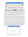
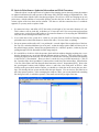
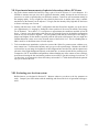
3. You have now defined a lens, but one with no curvature or thickness. Click on the Draw Off button near the top of the spreadsheet to open the ‘Autodraw’ window that will display a simple sketch of your setup, which will be updated from now on whenever you change something. Now select the RADIUS cell of surface 1 and enter 10, the radius that would yield a focal length of 20 cm for a thin PCX lens with an index of refraction of 1.5. In the APERTURE RADIUS fields for surfaces 1 and 2, enter 6, since the lens diameter we will use in the lab is 12 cm. In the THICKNESS field for surface 1, enter 2.5 to set the lens thickness, and in the THICKNESS field for surface 2, enter 4 to position the aperture stop. Now your drawing should show a PCX lens with the curved surface facing left. In the Efl field you can read the effective focal length of this lens, which should be 19.413079 cm. 4. For surface 3 (the aperture stop), we will use a calculated thickness so that the image plane will wind up at the paraxial focus. Start by clicking on the button in the THICKNESS cell and selecting Solves/Axial ray height. Accept the default value of zero in the data entry popup box by selecting ‘OK’. Now force the aperture stop to appear on the drawing: click the button in the SPECIAL cell for surface 3 and choose Surface Control/General in the new spreadsheet that appears, click the ‘Automatic’ button in the 5th row, and select Drawn on the pop-up menu that appears. Then click the green checkmark to complete the entry. Your drawing should now show the aperture stop with a dotted line 5. Repeat the same procedure for the SPECIAL cell in row 4 (but not the THICKNESS cell) to complete the basic lens design. Your drawing should now automatically extend to include the image plane for paraxial rays. Because some of the off-axis rays miss the image plane, extend it by entering 14 cm for the APERTURE RADIUS of surface 4 (IMS). There’s just one final thing to do: the lens needs to be shifted vertically so the 25 rays aren’t quite so far off center. Do this by selecting ‘C’ in addition to ‘F’ for row 3 (AST), bringing up the “Coordinate Data” box. Enter a vertical decentration of 2.4 cm by changing the value of DCY. Your finished drawing should appear as below. Click on the green check mark to save your spreadsheet and use File/Save Lens As on the main toolbar to save the design in a lens file, selecting an appropriate directory to store your work rather than the default. 3