1
Communicating Process Architectures 2004
Ian East, Jeremy Martin, Peter Welch, David Duce, and Mark Green (Eds.)
IOS Press, 2004
339
Using CSP to Verify Aspects of an
occam-to-FPGA Compiler
Roger M.A. PEEL and WONG Han Feng
Department of Computing, University of Surrey, Guildford, Surrey GU2 7XH, United Kingdom
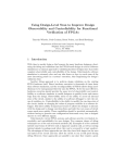
Abstract. This paper reports on the progress made in developing techniques for the
verification of an occam to FPGA compiler. The compiler converts occam 1 programs into logic circuits that are suitable for loading into field-programmable gate
arrays (FPGAs). Several levels of abstraction of these circuits provide links to conventional hardware implementations. Communicating Sequential Processes (CSP) has
then been used to model these circuits. This CSP has been subjected to tests for deadlock and livelock freedom using the Failures-Divergence Refinement tool (FDR). In
addition, FDR has been used to prove that the circuits emitted have behaviours equivalent to CSP specifications of the original occam source codes.
1 Introduction
occam is a language that permits parallel processes and blocking inter-process communications to be specified in a fine-grained structure which is particularly suitable for the implementation of embedded systems [1]. It forms the basis for languages such as Handel-C [2]
which can be compiled directly to a form that may be run on field-programmable gate arrays.
Since occam’s process and communication structure is derived from Hoare’s Communicating Sequential Processes (CSP) [3], many occam programs are therefore easily specified in
CSP.
Currently, a new version of the authors’ occam to FPGA compiler [4] is being built
to incorporate better circuit optimisation and further language features. During this reimplementation, it has become clear that design or coding faults in the logic generated by
the compiler are very difficult to find. This is because all of the logic gates operate in every
clock cycle. and values are latched into the flip-flops of the FPGA in parallel when required.
In contrast to sequential programs, much more can go wrong in parallel logic – and then
trigger other faults – in each clock cycle. Thus, techniques have been developed that allow
for the circuits to be checked for accuracy, such as building a dedicated simulator and circuit
visualiser within the compiler, and developing the formal verification technique presented in
this paper. By checking a number of such circuits, it should be possible to gain confidence in
the code generation of each section of the compiler.
The immediate application of the work reported in this paper, therefore, is to provide an
automatic mechanism for reference tests of elementary compiler functions. This could also
be performed by simulating the logic circuits that are generated, using suitable test vectors,
and then pattern-matching for particular results. On the other hand, running FDR [5] trace
refinements should be easier to automate, because small changes to the compiler would probably affect the test vectors required by the alternative approach. A second application is for
the verification of building-block processes that are then combined to build larger systems.
1
occam is a trademark of ST Microelectronics
340
R.M.A. Peel and Wong H.F. / Using CSP to Verify an occam-to-FPGA Compiler
Later on, it should be possible to reason about the behaviour of complete embedded systems,
either by modelling them in their entireties, or by composing these sectional results.
Section 2 of this paper provides further details of the background to this work, and lists
some of the alternative approaches that are employed. In Section 3, we explain how we used
CSP to model logic circuits. In Section 4, we show how a small occam counter program
was represented in CSP, and how we refinement-checked it against a CSP specification of
the task. Section 5 discusses occam channel communications, and Section 6 provides some
concluding remarks.
2 Background
Field-programmable gate array (FPGA) devices are components which contain configurable
blocks of low-level logic, typically comprising flip-flop storage elements, combinatorial
logic, and maybe special data processing units, memory blocks and even complete processors such as the PowerPC [6]. There are many ways to program FPGAs. Each manufacturer
usually provides basic schematic capture tools that allow low-level circuits to be drawn on a
computer screen, possibly incorporating macro elements that describe common sub-circuits
such as adders and multipliers. These diagrammatic representations are then optimised and
converted to the format that is sent to the FPGA at power-up, at which time it is configured to
perform the desired task. Some FPGAs may be entirely, or partially, re-configured later on,
too. The problem with designing at such a low level is that it is difficult to reason about the
circuits that have been constructed, leaving complicated simulations or hardware probing and
debugging as the main development techniques. As FPGAs become larger, this mechanism
scales poorly.
The VHDL design language provides a very low-level way to specify either the physical
or the behavioural characteristics of FPGA logic, in a way that allows a hierarchy of modules
to be built. Many library components are available for tasks such as arithmetic, and blocks
of logic (IP, or intellectual property) may be purchased for incorporation into larger designs.
Each of these blocks, as well as all of the more basic logic, operates in parallel, which can
lead to high performance, but which can also introduce concurrency issues that are not supported well by the design method. As in the schematic capture approach, VHDL designs are
usually tested through simulation. In order to evaluate the interaction of two asynchronous
components, the simulation test vectors must exercise all possible situations in which critical
interactions might occur – a very demanding requirement.
JHDL [7] represents logic elements as specially-developed Java classes, and provides
methods to allow the designer to specify their interconnections. The technique also provides
methods that can be used in the simulation phase, as well as back-end support for configuring
several popular FPGA device families.
At a higher-level of abstraction, it is possible to use conventional programming languages
to program FPGAs. Various authors and organisations have written compilers that convert
programs written in sequential languages such as C into logic for FPGAs. This approach is
limited by the amount of parallelism that can be discovered automatically in the C source
code. Better, non-standard parallel constructs can be added to a sequential language to represent various forms of parallelism. SystemC [8] does this in a thread-like manner; it also
implements event methods that provide a basis for synchronised communications. Handel-C
[2, 9] does the same, but was developed from an occam prototype and more closely follows
that model. Handel-C uses a synchronous message-passing, CSP-based, framework that was
originally modelled on occam. Unfortunately, it is possible to use the flexibility of its C-like
capabilities to defeat the security of the message-passing framework.
R.M.A. Peel and Wong H.F. / Using CSP to Verify an occam-to-FPGA Compiler
341
The authors therefore have chosen to retain an occam-like structure in their new compiler. The aim of the work is to develop a compilation environment that allows embeddedsystem designers to incorporate a high degree of message-passing parallelism in their designs,
to provide good timing properties and optimisations, and to be able to take advantage of proof
and verification techniques developed by the CSP community.
The compiler currently generates one-hot logic [10], in which a series of flip-flops are set
active when the program statements that they relate to are being executed. Further flip-flops
store each bit of each declared variable. In this way, program control is passed from one
statement to the next by activating the next flip-flop in a chain and clearing the previous one.
In sequential code, therefore, one flip-flop is in its active state (or hot) at any time – hence
one-hot. When a parallel program forks, the one-hot predecessor stage activates all of the
initial stages of the parallel processes; upon completion, the par-end must collect together all
of the parallel one-hot termination signals and only activate the following process when all
of its predecessors have terminated. Notice that each parallel process runs truly in parallel –
there is no concept of time-sharing as is seen in an implementation of a parallel (or threaded)
language on a uniprocessor. The flip-flops that hold the values of variables are triggered to
store a new value by the one-hot flip-flop that represents a particular assignment statement or
channel receive event.
In the future, other forms of logic, such as asynchronous, might be used by the compiler
as alternatives to clocked synchronous logic. This could well still use a one-hot structure, but
all of the logic elements would run at their own pace and synchronise with their neighbours
independently of a common clock. This scheme is more complicated to design, but typically
has a lower power consumption and generates lower levels of radio-frequency emissions.
The authors are aware that there are issues of metastability in all clocked digital logic
circuits. Metastability arises because a flip-flop (or single-bit storage cell) normally samples
its input on an incoming clock edge and reflects that value shortly thereafter. Unfortunately,
if the value of the input signal changes at the time of the clock edge, or shortly before it, or
shortly afterwards, then the value of the input is indeterminate and thus the value of the output
is unpredictable. Worse still, in this circumstance, the signal level on the flip-flop logic output
may not settle to the high or the low digital logic voltage level for a substantial period, which
upsets the logic that it feeds, too. Provided that the input signal does not change for a specified
set-up time before the clock is asserted, and provided that the input signal does not change for
a specified hold time afterwards, then the vendors of the implementation logic are prepared to
guarantee the metastable behaviour of their devices. In the circuits generated by our compiler,
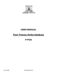
the inputs to all of the flip-flops are generated from combinations of the outputs of other flipflops (see Figure 1), so the round-trip times can easily be determined and the configuration
software can determine the maximum clock rate within which metastability should not occur.
The work presented in this paper does not address these issues further. Provided that the
vendors of the implementation logic are prepared to guarantee the metastable behaviour of
their devices, then our techniques – and those of every other digital designer - are considered
to be sound in this respect.
Another technique that is being used to generate fault-free logic for FPGAs is to start
with a formal algebra such as CSP and then to compile this directly to FPGAs, or alternatively to target an intermediate stage such as Handel-C [11], or the various Java-based CSP
implementations [12]. CSP currently provides most of the facilities required for embedded
systems, but issues such as timing, data structures and arithmetic capabilities still need good
solutions.
342
R.M.A. Peel and Wong H.F. / Using CSP to Verify an occam-to-FPGA Compiler
3 Method
3.1 Process Algebra and Model Checking
The scheme that has been employed in our research utilises the Communicating Sequential
Processes algebra to model both the behaviour of source occam programs and also of the
target logic circuits generated by the occam-to-FPGA compiler. The Failures-Divergence
Refinement (FDR) tool [5], produced by Formal Systems Europe Ltd, may then be used to
prove various properties of both the initial source and of the compiled logic circuits. These
properties can include deadlock freedom, livelock freedom, the behavioural equivalence of
two circuits, and the equivalence of a circuit with its formal (CSP) specification.
Although CSP has been used in our research, many forms of temporal logic would also
be appropriate to this task. SPIN and PROMELA have been used in [13]. Denis Nicole has
had success with SMV in [14]. However, he also concludes that state-space explosion can
easily occur as the systems under test increase in size. We chose CSP primarily so that we
could use the FDR model checker, which has proved to be very suitable.
3.2 Compiled Circuits
At present, our occam-to-FPGA compiler generates circuits using a relatively limited number of components – edge-triggered D-type and T-Type flip-flops, AND gates, OR gates,
inverters and input/output buffers. Each of these components has been modelled in CSP, and
thus a complete model of a circuit can be described using a number of these components,
connected by CSP channels, all running in parallel.
AND gate
in out
in
AND gate
in out
in
OR gate
in
in out
flip−flop
D
Q
clock
common
clock
fan−out
out
in
Figure 1: an example of part of a clocked FPGA circuit
Figure 1 shows just one flip-flop in a typical FPGA configuration, together with an ORgate and a layer of AND-gates. It also shows a fan-out (or delta) stage, which is not needed in
real hardware but is needed in a channel-based implementation when the channel output of a
process is copied to a number of process inputs. Although FPGAs are capable of containing
logic that is more complicated than this sum-of-products form, and although our occam
compiler generates such logic, this simple figure could be generalised to illustrate any valid
circuit. This example corresponds to the contents of a simple configurable logic block (or
CLB) of a typical Xilinx FPGA [6]. Notice that there is a cycle in this figure, and that the
flip-flop component is part of this cycle.
R.M.A. Peel and Wong H.F. / Using CSP to Verify an occam-to-FPGA Compiler
343
3.3 Modelling the Circuits with occam
In order to gain confidence with our strategy of modelling logic circuits in CSP, we started by
using occam to simulate some small circuits. Initially, we built an occam program that models a 3-input NAND gate. This program was run successfully using the Kent Retargettable
occam compiler (KRoC) [15]. The combinatorial 3-input NAND circuit has three inputs and
one output and each combination of its binary inputs can be exercised in turn to prove that
it operates as expected. This was done by supplying all eight possible combinations of the
three input signals and verifying the eight outputs in a simple occam test harness.
WHILE running
-- I/O-PAR process
SEQ
... parallel I/O (once on each channel)
... compute
WHILE running
-- I/O-SEQ process
SEQ
... parallel inputs (once on each input channel)
... compute
... parallel outputs (once on each output channel)
... compute
Figure 2: I/O-PAR and I/O-SEQ processes
Welch [16] introduces the concepts of I/O-PAR and I/O-SEQ processes, whose structures
are illustrated in Figure 2. In the former, all inputs and outputs operate in parallel and, thus,
each channel is used on every ‘heartbeat’ of the whole circuit, with each process locked into
step with its neighbours. Note that this is not a global lockstep – although that would be a
valid, but inefficient, refinement of these nearest-neighbour locksteps. In I/O-SEQ processes,
all of their inputs operate in parallel, but sequentially with the parallel combination of all of
their outputs.
Programs which contain just I/O-PAR processes, or those with mixtures of I/O-PAR and
I/O-SEQ processes, in which there are no cycles of just I/O-SEQ processes, are proven
deadlock-free [16, 17, 18, 19, 20]. This is a restrictive condition, of course; many programs
that do not follow these rules also turn out to be deadlock-free, especially if sufficient buffer
processes are provided.
Our NAND gate process was initially written as an I/O-PAR component. In this configuration, each of its inputs and outputs is communicated in parallel precisely once, then the
new state is determined. and then the parallel inputs and output are performed again, and so
on. In this way, arbitrary collections of NAND gates may be composed into a larger circuit
with no danger of deadlock. Furthermore, each combination will also be I/O-PAR and may
itself be composed with other components to make an even larger I/O-PAR program.
Six such NAND gates were then connected together in an occam program to form a Dtype flip-flop, using techniques similar to those also found in [16]. The circuit used, shown
in Figure 3, is one that is provided in dozens of digital logic text books and TTL data books
(e.g. [21]). This program was also executed using KRoC.
Welch notes in [16] that the I/O-PAR NAND gates each have a propagation delay of one
I/O-PAR cycle, and thus the set-up and hold times for the input signals had to be controlled
to ensure that the flip-flop’s data inputs were not changed within three cycles of the clock
edges. Variations of this constraint account for different numbers of delay cycles throughout
the work reported in this paper, and are seen in the set-up and hold times of all hardware
flip-flops, too.
344
R.M.A. Peel and Wong H.F. / Using CSP to Verify an occam-to-FPGA Compiler
PRESET
CLEAR
Q
Qbar
CLOCK
D
Figure 3: the edge-triggered D-type flip-flop initially implemented
3.4 Modelling the Circuits with CSP
Having experimented with occam models of these logic elements, we encoded the 3-input
NAND gate in CSP, composed six of them into a D-type flip-flop, and were then able to
experiment using FDR. Initially, we built an I/O-PAR version of the NAND gate in CSP, but
later we also built a version of the D-type flip-flop with I/O-SEQ NAND gates, together with
I/O-PAR output buffers (which render the whole ensemble I/O-PAR when the six NAND processes are combined) to ensure deadlock freedom. Again, the programs worked as expected,
and FDR was able to prove their deadlock properties and equivalence-check each of them
against the original version. By providing a filter process to translate a common stream of
input signals to that required to satisfy the set-up and hold time requirements of the different clock regimes, and by hiding all of the signals internal to that process, the effects of the
circuits could be proved to be equivalent.
The snag with these versions of our D-type flip-flop was that they generated very large
state spaces in FDR, although FDR was able to compact their initial requirements considerably. Despite this, however, it became clear that this 6-NAND mechanism for building
clocked logic elements was far too expensive to be built into large circuits.
Rather than building our flip-flops from first principles (e.g. 6 NAND gates), a more
practical approach turned out to be to build direct behavioural models and use them as base
components for the modelling of larger circuits. The equivalence between these behavioural
models and those structured out of NAND gates can easily be separately verified.
3.5 Problems with Modelling in CSP
We use the behavioural modelling in CSP of these flip-flops to illustrate one of the difficulties
CSP has in expressing certain simple patterns of behaviour – one of these being I/O-PAR!
Figure 4 shows the occam expression of these flip-flops. They are clearly I/O-PAR with
respect to their in and out channels. The clock represents a (general multiway) event that
other design rules (for the circuits constructed with this flip-flop) guarantee will not block
indefinitely – and, hence, may be safely considered part of the compute body of the I/O-PAR
cycle [20].
R.M.A. Peel and Wong H.F. / Using CSP to Verify an occam-to-FPGA Compiler
PROC dff (CHAN OF BOOL in, out,
CHAN OF BOOL clock)
INITIAL BOOL state IS FALSE:
WHILE TRUE
BOOL next:
SEQ
PAR
in ? next
out ! state
BOOL any:
clock ? any
state := next
:
345
PROC tff (CHAN OF BOOL in, out,
CHAN OF BOOL clock)
INITIAL BOOL state IS FALSE:
WHILE TRUE
BOOL flip:
SEQ
PAR
in ? flip
out ! state
BOOL any:
clock ? any
IF
flip
state := ˜state
TRUE
SKIP
:
Figure 4: The occam D-type and T-type flip-flops
There are no direct expressions in CSP of the patterns in Figure 4. However, there are
in Circus [22, 23] – an extension of CSP that includes state variables and assignment (and
formal Z specifications of state transformation).
Circus expressions for these flip-flops are shown in Figure 5. The loops are turned into
tail recursion with the state, whose value is preserved between loop cycles, becoming a parameter. This is a standard CSP mechanism.
The strange Circus idiom, dff in?tmp → (next := tmp), precisely captures the semantics of
the occam process, in ? next. There is no equivalent in CSP.
The CSP process, c?x → P (x), introduces a variable, x, whose scope extends only to the
process to the right of the arrow. Circus, which incorporates CSP, maintains this semantics
and is why we cannot simply write: dff in?next → Skip.
Unfortunately, we cannot use the Circus equations of Figure 5 in our work since, currently, model checkers do not exist for this algebra. We must translate into classical CSP to
be able to use FDR. There are two ways to do this, although neither is particularly elegant.
The first is to add more concurrency, as shown in Figure 6. The explicit Circus variable
is modelled by a separate CSP process, running in parallel with the flip-flop. Assignment and
reading of the variable are accomplished by channel communications (hidden from the view
of users of the flip-flop). The external I/O-PAR structure is explicitly preserved, although it
is seriously confused by the internal concurrency.
DFF (state ∈ {0, 1}) = var next ∈ {0, 1} •
(dff out!state → Skip ||| dff in?tmp → (next := tmp));
clock → DFF (next)
DFLIPFLOP = DFF (0)
TFF (state ∈ {0, 1}) = var flip ∈ {0, 1} •
(tff out!state → Skip ||| tff in?tmp → (flip := tmp));
clock → if (flip = 0) then TFF (state) else TFF (1 − state)
TFLIPFLOP = TFF (0)
Figure 5: The Circus D-type and T-type flip-flops
346
R.M.A. Peel and Wong H.F. / Using CSP to Verify an occam-to-FPGA Compiler
VARIABLE (value) = (put?x → VARIABLE (x) 2 get!value → VARIABLE (value))
DFF (state) = (dff out!state → Skip ||| dff in?tmp → put!tmp → Skip);
clock → get?next → DFF (next)
DFLIPFLOP = (DFF (0)
k
VARIABLE (0)) \ {put, get}
{put, get}
TFF (state) = (tff out!state → Skip ||| tff in?tmp → put!tmp → Skip);
clock → get?flip → if (flip = 0) then TFF (state) else TFF (1 − state)
TFLIPFLOP = (TFF (0)
k
VARIABLE (0)) \ {put, get}
{put, get}
Figure 6: The CSP D-type and T-type flip-flops – version 1
In fact, we prefer a solution that removes the explicit I/O-PAR concurrency, leaving sets
of external choices whose input variables retain sufficient scope to complete the recursion –
Figure 7. It’s not pretty but it yields relatively small state spaces for FDR to search.
DFF (state) = dff out!state → dff in?next → clock → DFF (next)
2
dff in?next → dff out!state → clock → DFF (next)
DFLIPFLOP = DFF (0)
TFF (state) = tff in?1 → tff out!state → clock → TFF (1 − state)
2
tff in?0 → tff out!state → clock → TFF state)
2
tff out!state → (tff in?1 → clock → TFF (1 − state)
2
tff in?0 → clock → TFF (state))
TFLIPFLOP = TFF (0)
Figure 7: The CSP D-type and T-type flip-flops – version 2
3.6 Modelling Higher-Level Circuits with CSP
The flip-flops in Section 3.5 were written according to the I/O-PAR rules in order to fit into
the higher-level circuit models of the form shown in Figure 9. We took advantage of the
characteristics of the FPGA target architecture of our occam compiler to produce a flip-flop
model that only requires a single CSP synchronisation event to signal the transition from one
circuit state to the next. We would need to use two clocks in an equivalent occam program,
to allow for the distributed nature of the individual clock channels in this environment. Our
new model uses considerably fewer states than the original flip-flop built from NAND gates.
The new, behavioural, CSP flip-flop model of Figure 7 replicates the start-up state of real
Xilinx FPGAs – all flip-flop values are initialised to zero when they are powered up.
Although true for the 6-NAND flip-flop as well, the new flip-flop follows the event-based
time model discussed in [24] and [25]. Rather than using specific timed CSP primitives,
event-based time relies on the distribution of a global tock signal which causes all of the
recipients to synchronise, thereby stepping simulated time forward by one cycle.
R.M.A. Peel and Wong H.F. / Using CSP to Verify an occam-to-FPGA Compiler
347
It was possible to use the trace refinement mechanisms in FDR to prove that the new
flip-flop – as well as all of the intermediate versions – behaved identically to the original
one, again allowing for their different clocking and setup / hold time regimes. When an
implementation process refines a CSP specification, it will not undertake any activities that
the specification is not prepared to perform. Trace refinement is the special case where the
activities referred to are CSP traces – lists of events. In order to verify that two processes
behave identically, one tests that one process refines the second, and that the second refines
the first. It is this result that we primarily used to compare our flip-flop designs, after taking
account of their different clocking requirements.
Whilst looking to minimise the state that FDR needs to analyse each component, it was
also discovered that it would be more economical to compose larger AND and OR gates
from combinations of 2-input devices. The CSP combinatorial AND and OR processes were
made I/O-SEQ in nature, rather than the I/O-PAR of the NAND gates used in the original
experiments. This is valid because they only appear as part of the input logic to the I/OPAR flip-flop components in our circuits, and thus cannot appear in cycles of solely I/O-SEQ
components. This is the condition required in [16] to ensure deadlock freedom – the original
NAND circuit had cycles around the NAND gates and thus required them to be I/O-PAR to
satisfy this rule.
4 Verifying Compiler Output
Having gained experience with small CSP processes modelling FPGA circuit elements, we
went on to examine the output of our occam-to-FPGA compiler in a similar manner. Initially
we tested the small occam program that is shown in Figure 8.
UINT2 x :
WHILE TRUE
SEQ
x := x PLUS 1
DELAY ()
-- a 2-bit unsigned integer, explained below.
-- a one-cycle delay, explained below.
Figure 8: the counter program source code
This program simply loops, incrementing the variable x each time. It separates each addition from the next with a DELAY() process. This is a compiler built-in PROC that translates
into a guaranteed one-cycle delay. It is introduced here to prevent an optimisation in our
compiler from scheduling successive assignments to be executed in consecutive clock cycles
– which would have been confusing to debug and analyse at the circuit level.
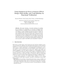
The program in Figure 8 uses a two-bit, unsigned, value for x – but this could be extended
to any number of bits with no impact on the results in this paper. It compiles to produce three
edge-triggered D-type flip-flops, which provide the sequencing logic, two T-Type flip-flops
which store the two bits of variable x, and a block of combinatorial logic that implements the
adder logic for the PLUS operator, together with the gating logic that stores the incremented
value when the assignment statement is active. These are shown in Figure 9.
This configuration can be implemented on a CPLD or on an FPGA directly, using its
single, common clock. The device manufacturers specify the maximum clock rate for which
such a configuration is guaranteed to operate properly. As mentioned in Section 3.6, a single
clock process in occam, outputting tock events on a single channel, would need to use a
fan-out process to clock each individual flip-flop, and would need to send two clock ticks in
each flip-flop cycle to ensure that all of the data values presented to the flip-flops were set-up
and held properly.
R.M.A. Peel and Wong H.F. / Using CSP to Verify an occam-to-FPGA Compiler
348
clock
VCC
init
combinatorial
logic
D
T
Q
Q
clk
x_bit_0
clk
D−type
T
T−type
x_bit_1
clk
ass4
Q
D
T−type
clk
Q
D−type
skip5
D
clk
Q
D−type
Figure 9: the counter circuit
This circuit was converted into CSP by hand, utilising the flip-flop and combinatorial
components described above. Once the technique becomes routine, we intend to produce
a CSP output route from our compiler, to generate CSP in FDR’s required textual notation
automatically.
Using FDR, it was then possible to prove that this circuit was deadlock and livelock free,
and to show that the trace of output values of the variable x counted 0, 1, 2, 3, 0, 1, 2, 3, ... ,
and so on.
Furthermore, it was possible to build a small CSP specification of this counting cycle and
to verify, using FDR trace-refinement, that the compiled occam program generates the same
sequence of outputs as its specification. This CSP specification is shown in Figure 10.
COUNTER = out!0 → out!0 → out!1 → out!1 → out!2 → out!2 → out!3 → out!3 → COUNTER
Figure 10: the CSP specification of the counter process
The CSP COUNTER generates output values along a channel, out, whilst the occam
program shown in Figure 8 simply stores updated values into the bits of variable x. In order
to reconcile these two representations of the counter output, a CSP process has been written
to convert the values of the T-type flip-flops into a single channel that carries integer values.
This CSP is not illustrated in this paper. The reason that the CSP processes that represent
representing flip-flops store integer values (i.e. 0 and 1) rather than Booleans is due to the
complexity of this conversion process. Other ways of converting, outputting and comparing
integer values will be explored in the future.
The repetition of the outputs in Figure 10 is required because the simulations are cyclerealistic – and one CSP event takes place on each simulated clock cycle. The repeated operations are caused by the DELAY() process in the original program shown in Figure 8. In
occam programs with more complicated timing properties, such as the evaluation of expressions which might take a variable number of cycles, we intend just to compare selected events
R.M.A. Peel and Wong H.F. / Using CSP to Verify an occam-to-FPGA Compiler
349
rather than all of them. This could be done by hiding more of the internal state of the CSP
processes before conducting the refinement checks. Of course, cycle-realistic timing might
be an important circuit property, for instance in the video output buffer in [4], in which case
this behaviour could be examined directly.
There were some initialisation issues in the CSP simulation of the circuit, which showed
up as extra values emitted on the outputs of the flip-flops at start-up. These were caused
by the internal I/O-PAR nature of the combinatorial components and had to be replicated in
the CSP program specification, or avoided by comparing traces of just assignments or just
occam channel communications. We have now eliminated them from the generated circuit
by using I/O-SEQ processes for the combinatorial components throughout. The flip-flop
processes remain I/O-PAR, of course, and thus appear in every cycle of the programs and
keep them deadlock-free. Consequently, circuits modelled using CSP specifications generate
exactly the same traces in FDR as in the FPGA logic simulator.
Having obtained the CSP results described above, we also implemented this counter circuit in occam, making a high-level simulation of our FPGA circuit. In this case, the flip-flops
were still made I/O-PAR, and the combinatorial logic components were I/O-SEQ. Because
the FPGA clock signal was represented as a fanned-out group of clock channels, it was theoretically necessary to introduce a double-clock arrangement to ensure that all of the combinatorial elements had completed their actions before the flip-flops triggered to start the next
clock cycle. This particular counter circuit is sufficiently regular in operation that the roundrobin scheduling of KRoC causes the processes to execute in the right order even without the
double-edged clock, but this cannot be guaranteed to happen – future schedulers and multiprocessor implementations may be different. The actual occam codes used for the flip-flops
in this simulation, therefore, were the same as those in Figure 4 except that the clock ? any
lines are duplicated – i.e. they pause in each cycle for two clock channel communications,
corresponding to falling and rising edges in an electronic implementation.
Our counter circuit, manually translated to 240 lines of occam and interfaced to input and
output conversion processes, ran perfectly and generated the expected incrementing counter
values.
5 Further Work – Channel Communications
While the example in the previous section is very small and simple, it it does demonstrate an
endless loop, a simple ripple carry adder, read and write access to a variable, a delay process
and sequential composition. Much more important – to the implementation of the compiler
– will be correctness proofs of occam channel communication, a circuit’s behaviour at the
beginning and end of parallel constructs, channel alternation (ALT), and the handling of input
and output ports on the periphery of the circuit.
Figure 11 shows the occam source code of a program that explores the relationships
between channel communications whose transmitter and receiver become ready in the same
cycle, or when the transmitter becomes ready first or when the receiver becomes ready first.
The logic circuits generated by our compiler implement the blocking behaviour of the channel
communications in these cases. The delays provide additional cycles to ensure that, following
the previous synchronising channel communication, the intended process becomes ready first
for the next communication. More delays are provided than strictly needed to provide the
necessary timing relationships, but the extras allow the operation of the successive channel
communications to be completely separated in time – this assists manual inspection of the
FPGA simulator and CSP traces. This circuit compiles down to 29 flip-flops with several
rather large sum-of-products (AND/OR/NOT) equations.
350
R.M.A. Peel and Wong H.F. / Using CSP to Verify an occam-to-FPGA Compiler
CHAN OF UINT2 a:
PAR
UINT2 w, x, y:
SEQ
DELAY ()
a ? w
DELAY ()
DELAY ()
DELAY ()
a ? x
DELAY ()
a ? y
SEQ
DELAY ()
a ! 2
DELAY ()
a ! 3
DELAY ()
DELAY ()
DELAY ()
a ! 1
-- sender and receiver
-- become ready simultaneously
-- sender ready
-- before
-- receiver
-- receiver ready
-- before
-- sender
Figure 11: A channel communication test (where the parallel processes have been laid out side-by-side to reflect
their timing behaviour)
It has not yet been possible to generate its CSP equivalent manually. Instead, we have
worked on the three separate timing circumstances individually, and these are shown in Figure 12.
-- sender first
-- receiver first
-- simultaneous
CHAN OF UINT2 ch:
PAR
CHAN OF UINT2 ch:
PAR
CHAN OF UINT2 ch:
PAR
UINT2 rx:
SEQ
DELAY ()
ch ? rx
SEQ
ch ! 3
UINT2 rx:
SEQ
ch ? rx
SEQ
DELAY ()
ch ! 1
UINT2 rx:
SEQ
DELAY ()
ch ? rx
SEQ
DELAY ()
ch ! 2
Figure 12: Three channel communication sub-tests
The correct re-use of channel a three times in the original program cannot be tested in
the three separate sub-programs, so the verification of the combined program in Figure 11,
possibly with some of the DELAY()s removed, will still be required to provide complete
confidence of the compiler’s generation of the channel communication logic. Verifying the
re-use of variables and channels is just the sort of proof for which this CSP technique will be
most useful. In practice, using separate channels in Figure 11 would reduce the gating logic
considerably and would be the preferred choice. Similarly, if a variable is used to store two
independent values at different times in the execution of a program, it is usually beneficial
to use two variables when the program is compiled to FPGA. Indeed, a source-code-level
optimiser could identify where separate channels or variables would be more economical
than re-used ones and spawn the separate instances appropriately.
The three occam programs in Figure 12 compile to 8, 8 and 10 flip-flops, respectively.
The re-use of channel a, as well as the replicated start-up logic, explains why the number of
flip-flops does not sum to 29.
R.M.A. Peel and Wong H.F. / Using CSP to Verify an occam-to-FPGA Compiler
351
These three programs were laboriously hand-converted to CSP – yielding files of approximately 1100, 1100 and 1200 lines of machine-readable CSP in the three cases. The three
programs are very similar – essentially the simultaneous one has two delays before communication starts on the channels, and the other two have one of these delays removed. Careful
use of the FDR sbisim() compression routine is able to keep the state space manageable in
these cases, and the trace refinements take around five to ten seconds each (on a modestlypowerful PC). In each case, the value transmitted is seen to arrive in the bits of the destination
variable.
Since enlargement of the circuits being verified very quickly leads to a huge number of
circuit states being explored in FDR, we have developed informal strategies for combining
the CSP representations of circuit components, using sbisim(), in an efficient manner.
Basically, pairs of gates that share relatively few inputs, and that are directly connected by
signals that do not propagate anywhere else, are good candidates for compression. However,
it does not yet appear to be straightforward to automate this activity in our compiler.
6 Conclusions
So far, it has been possible to demonstrate that small occam programs, compiled into digital logic circuits suitable for running on FPGAs, have the same behaviours as their CSP
specifications. The stages used to construct these assertions may be traced back to the most
basic fundamentals of digital logic, and these building blocks are very small and thus also
easy to justify as correct on pragmatic grounds. Our experience is that logic circuits that have
undergone analysis using these techniques behave predictably and correctly on real hardware.
The scheme introduced above shows considerable promise in allowing circuits generated
from occam programs to be validated. This is currently being exploited to automate the
reference-testing of successive iterations of the compiler. In addition, it is possible to verify
complete parallel processes, together with their simple test harnesses, before building them
into embedded systems. Provided that the compiler’s composition logic has also been verified, this should provide considerable confidence that the embedded programs are accurate.
Jonathan Phillips and Dyke Stiles at Utah State University are working on the automated
translation of an occam-like subset of CSP to Handel-C [11], for onward translation to FPGA
logic. The work reported in this paper could provide an interesting verification route for their
developments, too.
Acknowledgements
We would like to thank Peter Welch, Dyke Stiles, Jim Woodcock and Alistair McEwan for
their discussions and the suggestions that they have made – directly and indirectly – during
the production of this paper.
References
[1] INMOS Limited. Occam2 Reference Manual. Prentice-Hall, 1988. ISBN 0-13-629312-3.
[2] I. Page & W. Luk. Compiling occam into FPGAs. In W. Moore & W. Luk, eds, FPGAs , pages 271-283,
Abingdon EE&CS books, 1991.
[3] C.A.R. Hoare. Communicating Sequential Processes. Prentice-Hall, 1985, ISBN 0-13-153289-8.
[4] R.M.A. Peel & B.M. Cook. Occam on Field Programmable Gate Arrays - Fast Prototyping of Parallel
Embedded Systems In H.R. Arabnia, ed, the Proceedings of the International Conference on Parallel and
352
R.M.A. Peel and Wong H.F. / Using CSP to Verify an occam-to-FPGA Compiler
Distributed Processing Techniques and Applications (PDPTA’2000), pages 2523-2529, CSREA Press,
June 2000. ISBN 1-892512-51-3.
[5] Formal Systems (Europe) Ltd., Oxford. Failures-Divergence Refinement – the FDR User Manual, version
2.80. 2003.
[6] Refer to www.xilinx.com for datasheets and product overviews on the Xilinx Virtex-II Pro.
[7] Peter Bellows and Brad Hutchings. JHDL – An HDL for Reconfigurable Systems. in Proceedings of the
IEEE Symposium on Field-Programmable Custom Computing Machines, April 1998.
[8] Stuart Swan. An Introduction to System Level Modeling in SystemC 2.0. available at http://www.
systemc.org/projects/sitedocs/document/v201\_White\_Paper/en/1, 2001, referenced July 2004.
[9] Ian Page et al. Advanced Silicon Prototyping in a Reconfigurable Environment. in P.H. Welch et al., eds,
Proceedings of WoTUG-21, pages 81 - 92, IOS Press, Amsterdam, 1998, ISBN 90-5199-391-9.
[10] S. Knapp. Accelerate FPGA Macros with One-Hot Approach. in Electronic Design, 13th Sept. 1990.
[11] J.D. Phillips. An Automatic Translation of CSP to Handel-C. M.Sc. Thesis, Utah State University, 2004.
[12] V. Raju, L. Rong and G.S. Stiles. Automatic Conversion of CSP to CTJ, JCSP, and CCSP. in Jan F.
Broenink and Gerald H. Hilderink, eds, Communicating Process Architectures 2003, pages 63-81, IOS
Press, Amsterdam, 2003, ISBN 1-58603-381-6.
[13] J. Pascoe and R. Loader. Consolidating The Agreement Problem Protocol Verification Environment. in
Communicating Process Architectures 2002. IOS Press, Amsterdam, 2002, ISBN 1-58603-268-2.
[14] D.A. Nicole, S. Ellis and S.Hancock. occam for reliable embedded systems: lightweight runtime and
model checking. in Communicating Process Architectures 2003, pages 167-172, IOS Press, Amsterdam,
2003, ISBN 1-58603-381-6.
[15] D.C. Wood and P.H. Welch. The Kent Retargettable occam Compiler. in Proceedings of WoTUG-19,
pages 143-166, IOS Press, Amsterdam, April 1996, ISBN 90-5199-261-0.
[16] P.H. Welch. Emulating Digital Logic using Transputer Networks (very high parallelism = simplicity = performance). in Proc. PARLE’87 – Parallel Architectures and Languages Europe, pages 357-373, SpringerVerlag, 1987.
[17] P.H. Welch and G.R. Justo. On the serialisation of parallel programs. in J. Edwards, ed, Proceedings of
WoTUG-14, pages 159-180, IOS Press, Amsterdam, 1991, ISBN 90-5199-063-4.
[18] P.H. Welch, G.R. Justo, and C.J. Willcock. Higher-Level Paradigms for Deadlock-Free High-Performance
Systems. In Transputer Applications and Systems ’93, pages 981–1004, Aachen, Germany, September
1993. IOS Press, Netherlands. ISBN 90-5199-140-1.
[19] J.M.R. Martin, I. East, and S. Jassim. Design Rules for Deadlock Freedom. Transputer Communications,
3(2):121–133, September 1994. John Wiley and Sons. 1070-454X.
[20] J.M.R. Martin and P.H. Welch. A Design Strategy for Deadlock-Free Concurrent Systems. Transputer
Communications, 3(4):215–232, October 1996. John Wiley and Sons. 1070-454X.
[21] Texas Instruments. The TTL Data Book. 3rd edition, 1979 (ISBN 0-904047-27-X).
[22] A.L.C. Cavalcanti, A.C.A. Sampaio, and J.C.P. Woodcock. A Refinement Strategy for Circus. Formal
Aspects of Computing, 15(2-3):146–181, November 2003.
[23] M. Oliveira, A.L.C. Cavalcanti, and J. Woodcock. Refining Industrial Scale Systems in Circus. In Communicating Process Architectures 2004, WoTUG-27, ISSN 1383-7575, pages 281–309, IOS Press, Amsterdam, The Netherlands, September 2004.
[24] A.W. Roscoe. The Theory and Practice of Concurrency. Prentice Hall, 1998.
[25] Steve Schneider. Concurrent and Real-Time Systems: the CSP approach, John Wiley & Sons Ltd., 2000